

Page 1

AN3258
Application note
STM8A/S HSI oscillator calibration
using LIN automatic resynchronization
Introduction
Local interconnect network (LIN) is a widely used standard for communication between
various nodes present inside the electronic control unit (ECU) of a vehicle. LIN sync frame,
which is defined by LIN standard, is used as a reference by the LIN slave nodes for clock
synchronization. Using this technique, LIN slave nodes can calibrate the variable internal
RC oscillator and use it as the system clock source. Therefore, the LIN slave node
application can save the cost of using crystal or resonator oscillators.
This application note describes a method to calibrate the STM8A/S high-speed internal
(HSI) oscillator using the LIN automatic resynchronization feature of the LINUART/UART1
peripheral. The calibration method is also provided with a software routine. It can be
downloaded from www.st.com.
The user must be familiar with the LIN bus standard, STM8A/S microcontroller architecture,
and the basics of C language. Detailed information about the STM8A/S microcontroller
peripheral features, hardware registers, and electrical characteristics are available in the
STM8A (RM0009) and STM8S (RM0016) reference manuals and the product datasheets.
October 2010 Doc ID 17825 Rev 1 1/16
www.st.com
Page 2

Contents AN3258
Contents
Introduction . . . . . . . . . . . . . . . . . . . . . . . . . . . . . . . . . . . . . . . . . . . . . . . . . . . . . . . . . 1
1 HSI calibration . . . . . . . . . . . . . . . . . . . . . . . . . . . . . . . . . . . . . . . . . . . . . . 5
1.1 HSI trimming bits . . . . . . . . . . . . . . . . . . . . . . . . . . . . . . . . . . . . . . . . . . . . 5
1.2 LIN automatic resynchronization . . . . . . . . . . . . . . . . . . . . . . . . . . . . . . . . 6
1.3 HSI calibration method . . . . . . . . . . . . . . . . . . . . . . . . . . . . . . . . . . . . . . . . 8
1.4 HSI calibration routine . . . . . . . . . . . . . . . . . . . . . . . . . . . . . . . . . . . . . . . . 9
1.5 LIN header error handling . . . . . . . . . . . . . . . . . . . . . . . . . . . . . . . . . . . . 11
1.6 LIN divider update method . . . . . . . . . . . . . . . . . . . . . . . . . . . . . . . . . . . . 11
1.7 LIN clock deviation . . . . . . . . . . . . . . . . . . . . . . . . . . . . . . . . . . . . . . . . . . 13
2 Conclusion . . . . . . . . . . . . . . . . . . . . . . . . . . . . . . . . . . . . . . . . . . . . . . . . 14
3 Revision history . . . . . . . . . . . . . . . . . . . . . . . . . . . . . . . . . . . . . . . . . . . 15
2/16 Doc ID 17825 Rev 1
Page 3

AN3258 List of tables
List of tables
Table 1. CLK_HSITRIMR values and binary two’s complement representation. . . . . . . . . . . . . . . . . 6
Table 2. Document revision history . . . . . . . . . . . . . . . . . . . . . . . . . . . . . . . . . . . . . . . . . . . . . . . . . 15
Doc ID 17825 Rev 1 3/16
Page 4

List of figures AN3258
List of figures
Figure 1. STM8A/S HSI trimming principle . . . . . . . . . . . . . . . . . . . . . . . . . . . . . . . . . . . . . . . . . . . . . 5
Figure 2. LIN header . . . . . . . . . . . . . . . . . . . . . . . . . . . . . . . . . . . . . . . . . . . . . . . . . . . . . . . . . . . . . . 7
Figure 3. LIN synch field measurement . . . . . . . . . . . . . . . . . . . . . . . . . . . . . . . . . . . . . . . . . . . . . . . . 7
Figure 4. HSI calibration routine flowchart . . . . . . . . . . . . . . . . . . . . . . . . . . . . . . . . . . . . . . . . . . . . . 10
Figure 5. LDIV read/write operations when LDUM = 0 . . . . . . . . . . . . . . . . . . . . . . . . . . . . . . . . . . . 12
Figure 6. LDIV read/write operations when LDUM = 1 . . . . . . . . . . . . . . . . . . . . . . . . . . . . . . . . . . . 12
4/16 Doc ID 17825 Rev 1
Page 5
AN3258 HSI calibration
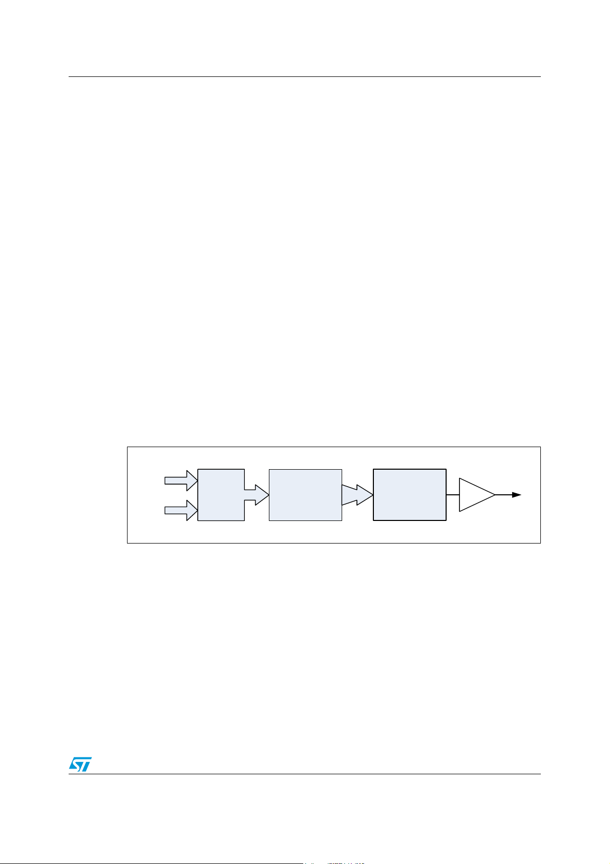
RC OSCILLATOR
DECODER
CLK_HSITRIM
HSI Clock Output
+
INIT_TR IM
1 HSI calibration
1.1 HSI trimming bits
STM8A/S microcontrollers have an HSI oscillator with a nominal frequency (f
which is factory calibrated at an ambient temperature (T
(V
) of 5 V. The accuracy for overall temperature and voltage range is ±5 % (please refer to
CC
) of 25 °C and a supply voltage
A
) of 16 MHz
HSI
the device specific datasheet) which is sufficient for many applications. For a given voltage
and temperature condition, the HSI oscillator frequency can be calibrated to ±1 % or ±0.5 %
by using calibration bits as described below and in Figure 1.
After a device reset, the factory calibration value at T
= 25 °C and VCC = 5 V is
A
automatically loaded into the internal calibration register. The HSI frequency can be finetuned by writing the calibration bits present in the HSI clock calibration trimming register
(CLK_HSITRIMR). The maximum number of calibration bits present is either three or four
depending on the device. The calibration bits provide an additional trimming value which is
added to the factory calibration value to fine-tune the HSI output frequency. The additional
trimming value, written in the trimming bits, is interpreted as a signed value with two’s
complement representation (see Tab l e 1 ). In the case of three trimming bits, this additional
trimming value can vary from -4 (100b) to 3 (011b) and in the case of four trimming bits, this
additional trimming value varies from -7 (1001b) to 7 (0111b). Thus, the additional trimming
value can be added or subtracted to the factory calibration value. An increase in the
trimming value causes a decrease in the HSI frequency. The frequency change per step is
±1 % or ±0.5 % depending on the device and number of trimming bits used (three or four).
Some devices can use either three or four trimming bits which are programmable via the
HSITRIM option byte.
Figure 1. STM8A/S HSI trimming principle
Doc ID 17825 Rev 1 5/16
Page 6

HSI calibration AN3258
Table 1. CLK_HSITRIMR values and binary two’s complement representation
3-bit trimming value 4-bit trimming value
Decimal
value
3 011b 7 0111b
2 010b 6 0110b
1 001b 5 0101b
0 000b 4 0100b
-1 111b 3 0011b
-2 110b 2 0010b
-3 101b 1 0001b
-4 100b 0 0000b
Binary two’s
complement value
Decimal
value
-1 1111b
-2 1110b
-3 1101b
-4 1100b
-5 1011b
-6 1010b
-7 1001b
Binary two’s complement
value
1.2 LIN automatic resynchronization
In the LIN standard, the master node initiates the communication by sending a LIN message
header to the slave node. The LIN message header sent by the master node comprises
three fields (see Figure 2):
● Break field
● Sync field
● Identifier field
– frame identifier
– parity
The break field is at least 13 nominal bit times the dominant value followed by a break
delimiter. The sync field is a byte with a data value of 0x55. The identifier field consists of
two subfields: the frame identifier and the parity. Bits 0 to 5 are frame identifier and bits 6 to
7 are the parity.
6/16 Doc ID 17825 Rev 1
Page 7

AN3258 HSI calibration
LIN break LIN synch Identifier
Parity bits
field
field
LIN break
Break
Bit0
Bit1
Bit2
Bit3
Bit4
Bit5 Bit6
Bit7
Start
bit
Stop
bit
Next
start
bit
LIN synch field
Measurement = 8.TBR = SM.T
MASTER
LDIV(n)
LDIV(n+1)
T
BR
delim.
Figure 2. LIN header
Usually, the master node uses a crystal or resonator oscillator to generate the correct baud
rate. The sync field byte is used by the slave node to synchronize with the master clock.
The STM8A/S LINUART peripheral has an automatic resynchronization feature which
makes use of the sync byte field to synchronize with the master baud rate. The automatic
resynchronization feature measures the sync byte field and automatically adjusts the slave
baud rate generator after each LIN sync field reception from the master node (see Figure 3).
Figure 3. LIN synch field measurement
Note: f
After each LIN break reception, the time duration between five falling edges on the LIN Rx
pin is sampled on the f
MASTER
clock. The result of this measurement is stored in an internal
19-bit register called SM which is not user accessible. Then, the LIN baud rate divider
(LDIV) is automatically updated at the end of the fifth falling edge.
MASTER
and T
MASTER
are the respective system clock frequency and time period of the
STM8A/S slave node (please refer to the clock tree figure in the STM8A and STM8S
reference manuals) and should not be considered as the frequency of the master node.
Doc ID 17825 Rev 1 7/16
Page 8

HSI calibration AN3258
f
HSIDIV""
f
HSI
HSIDIV
------------------- -=
Baudrate
f
MASTER
LDIV_NOM
------------------------------=
LDIV_NOM
f
MASTER
Baudrate
--------------------------=
f
MESASURED
LDIV_MEAS Baudrate=
FREQUENCYfMASTERfMEASURED
–=
1.3 HSI calibration method
This section explains how to calibrate the HSI oscillator using the LIN automatic
resynchronization feature described above. The automatic resynchronization feature
updates the LIN baud rate divider (LDIV) after each LIN sync field reception. The calibration
method uses the updated LDIV factor to calculate the HSI frequency variation, under current
conditions, using the equations below.
Equation 1
Where, f
= nominal HSI frequency of 16 MHz and HSIDIV is the HSI prescaler factor
HSI
programmed in the CLK_CKDIVR register.
The LIN baud rate is programmed by software after writing the LDIV_NOM value into the
BRR1 and BRR2 registers.
Equation 2
As slave node uses the HSI clock as f
MASTER
, f
MASTER
= f
HSIDIV
.
Equation 3
Equation 4
After the LIN sync field reception, the LIN baud rate divider is measured by the automatic
resynchronization (LDIV_MEAS) and it is automatically loaded into the BRR1 and BRR2
registers. These actions keep the same baud rate under varying HSI oscillator frequency
conditions. The LDIV_MEAS factor multiplied by the baud rate gives the current HSI
frequency (f
MEASURED
).
Where, LDIV_MEAS = LDIV measured after automatic resynchronization.
The difference between the f
frequency.
Equation 5
Where, Δ
8/16 Doc ID 17825 Rev 1
FREQUENCY
REFERENCE
and f
MEASURED
gives the variation of HSI oscillator
is the HSI oscillator frequency variation.
Page 9

AN3258 HSI calibration
1.4 HSI calibration routine
The calibration routines are written in C language. They include STM8A/S firmware library
functions.
The calibration routine starts with the configuration of the HSI clock prescaler value bits,
HSIDIV[1:0], in the CLK_CKDIVR register. The value programmed in the software example
is HSIDIV[1:0] = 00 which means, f
HSITRIM[3:0] or HSITRIM[2:0], in the CLK_HSITRIMR register are kept at reset value.
The LINUART peripheral is initialized at baud rate 19200 bps, 8 data bits, 1 stop bit and no
parity. LINUART is configured in slave mode (LSLV bit =1) with the automatic
resynchronization feature enabled (LASE bit = 1) and the LIN divider update method
(LDUM) bit = 0. Both LIN header detection(LHDIEN) and LIN receiver (RIEN) interrupts are
enabled. The LINEN bit is set to enable the LIN mode.
When a valid LIN header is received by the LIN slave, the LIN receive interrupt is generated.
Inside the interrupt service routine, if the LIN header detection flag (LHDF) is set,
LDIV_MEAS
f
MEASURED
is read from the BRR1 and BRR2 registers (see Figure 4). Using Equation 4,
is calculated. The variation of the HSI oscillator frequency (Δ
calculated by using Equation 5.
HSIDIV
= f
= 16 MHz. The HSI trimming bits,
HSI/1
FREQUENCY
) is
Depending on whether the Δ
FREQUENCY
is positive or negative, the trimming value (as
described in Section 1.1: HSI trimming bits) is written to increase or decrease the HSI
oscillator frequency by one trimming step. When the next sync frame is received, the
procedure is repeated to check and calibrate the HSI oscillator until the trimming value
reaches the upper/lower limit or until the measured Δ
FREQUENCY
is greater than the value
measured with the previous trimming value. The maximum number of valid LIN headers
required to calibrate the HSI oscillator is four if three trimming bits are used and eight if four
trimming bits are used.
Doc ID 17825 Rev 1 9/16
Page 10

HSI calibration AN3258
AI
-AINROUTINE
#ONFIGURETHE(3)CLOCKPRESCALER
)NITIALIZETHE,).5!24
%NABLEINTERRUPTS
)NFINITELOOP
WAITINGFOR,).RECEIVEINTERRUPT
,).RECEIVEINTERRUPT
SERVICEROUTINE
6ARIATIONAND
(3)42)-VALUE
42)-?-).?6!,5%
6ARIATIONAND
(3)42)-VALUE
42)-?-!8?6!,5%
,($&FLAG
,$)6?-%!3VALUEREADFROM
"22AND"22F
-%!352%$
,$)6?-%!3"AUDRATE
9E S
.O
#HECKFOR,(%FLAG
ANDCLEARIF
%ND
!
6ARIATION
F
-!34%2
F
-%!352%$
.O
0OSITIVEVARIATION
(3)42)-(3)42)-
0OSITIVEVARIATION
NEGATIVEVARIATION
42)--).'$)3!",%
(3)42)-(3)42)-
9E S
9E S
.EGATIVEVARIATION
(3)42)-(3)42)-
.EGATIVEVARIATION
POSITIVEVARIATION
.O
42)--).'$)3!",%
(3)42)-(3)42)-
9E S
!
2ELOADTHE,$)6./-VALUE
"22)NITVALUE
"22)NITVALUE
%NDOF,).5!24
INTERRUPTSERVICEROUTINE
42)--).'$)3!",%
Figure 4. HSI calibration routine flowchart
10/16 Doc ID 17825 Rev 1
Page 11

AN3258 HSI calibration
1.5 LIN header error handling
It is possible that slave node receives an invalid LIN header or a LIN header with an error. In
this case, the LIN header detection flag (LHDF) is not set and the corresponding LIN header
detection interrupt does not occur but, the LIN header error (LHE) flag is set.
A LIN header error may occur under the following conditions:
1. The break delimiter is too short.
2. The sync field is not equal to 0x55 or the deviation error in the sync field is outside the
LIN specification which allows a clock deviation of up to 14 % between the slave and
master oscillators.
3. The framing error occurs in the sync field or the identifier field.
4. A LIN header reception timeout occurs.
In the case of a LIN header error detection (LHE bit set), the LHE bit is cleared inside the
interrupt service routine and the software waits for the new valid LIN header.
1.6 LIN divider update method
Three registers are managed internally by the LINUART/UART1 peripheral for the automatic
update of the LIN divider (LDIV). They are:
1. LDIV_NOM which stores the value written by software in the LINUART_BRR1 and
LINUART_BRR2 registers.
2. LDIV_MEAS which stores the value of the LIN sync field measurement.
3. LDIV which stores the value which is used to generate the baud rate.
The LDIV can be updated from the LDIV_MEAS register after the LIN sync field
measurement or from the LDIV_NOM register after a software write in LINUART_BRR1.
If LASE =1, the LDIV_MEAS is loaded automatically into LDIV after each LIN sync field
measurement. The loading from LDIV_NOM into LDIV depends on the LDUM bit setting.
If LDUM = 1, the LDIV_NOM value is loaded automatically into LDIV register at the end of
character reception (RXNE =1).
If LDUM =0, the LDIV_NOM value is loaded into LDIV after a software write into
LINUART_BRR1.
If the loading from LDIV_MEAS and LDIV_NOM into LDIV occurs at the same time,
LDIV_NOM has the priority.
Doc ID 17825 Rev 1 11/16
Page 12

HSI calibration AN3258
LDIV
LDIV_NOM
Baud rate
Read LINUART_BRR1
Write LINUART_BRR2
Update
at end of
synch field
LDIV[3:0]
LDIV[11:4]
LDIV_MEAS
Write LINUART_BRR1
Read LINUART_BRR2
generation
LIN sync field
measurement
Write
LINUART_BRR1
LDIV[15:2]
LDIV[3:0]
LDIV[7:0]
LDIV[15:12]
LDIV[3:0]
LDIV[11:4]
LDIV[15:12]
LDIV
LDIV_NOM
Baud rate
Read LINUART_BRR1
Write LINUART_BRR2
Update
RXNE=1
at end of
synch field
LDIV_MEAS
Write LINUART_BRR1
Read LINUART_BRR2
generation
LIN sync field
measurement
LDUM is reset
LDIV[3:0]
LDIV[11:4]
LDIV[15:12]
LDIV[3:0]
LDIV[11:4]
LDIV[15:12]
LDIV[3:0]
LDIV[11:4]
LDIV[15:12]
In Figure 5, the software example has been implemented with (LDUM = 0). After the LIN
reception of the LIN header interrupt and the execution of the calibration routine, the LDIV is
loaded with LDIV_NOM by writing the LINUART_BRR1.
Figure 5. LDIV read/write operations when LDUM = 0
In the case of LDUM = 1 (see Figure 6), the LDUM bit has to set by software before the LIN
checksum reception. In this way, the LDIV_NOM is loaded into LDIV at the end of character
reception.
Figure 6. LDIV read/write operations when LDUM = 1
12/16 Doc ID 17825 Rev 1
Page 13

AN3258 HSI calibration
1.7 LIN clock deviation
LIN clock deviations may be caused by the following sources:
1. Deviation due to transmitter error (DTRA): The transmitter can be either a master or a
slave (in the case of a slave listening to the response of another slave).
2. Error due to the LIN synch measurement performed by the receiver (DMEAS).
3. Error due to the baud rate quantization of the receiver (DQUANT).
4. Deviation of the local oscillator of the receiver (DREC): This deviation can occur during
the reception of one complete LIN message assuming that the deviation was
compensated at the beginning of the message.
5. Deviation due to the transmission line (DTCL) which is generally due to the
transceivers.
Total clock deviation = DTRA + DMEAS + DQUANT + DREC + DTCL
If the LINUART is to receive a character correctly, the total deviation should be <3.75 %. For
more details, please refer to the STM8A (RM0009) and STM8S (RM0016) reference
manuals.
Doc ID 17825 Rev 1 13/16
Page 14

Conclusion AN3258
2 Conclusion
The calibration method described in this application note allows the LIN slave nodes to
calibrate and operate with the HSI internal oscillator (16 MHz) under variable temperature
and voltage conditions.
14/16 Doc ID 17825 Rev 1
Page 15

AN3258 Revision history
3 Revision history
Table 2. Document revision history
Date Revision Changes
05-Oct-2010 1 Initial release
Doc ID 17825 Rev 1 15/16
Page 16

AN3258
Please Read Carefully:
Information in this document is provided solely in connection with ST products. STMicroelectronics NV and its subsidiaries (“ST”) reserve the
right to make changes, corrections, modifications or improvements, to this document, and the products and services described herein at any
time, without notice.
All ST products are sold pursuant to ST’s terms and conditions of sale.
Purchasers are solely responsible for the choice, selection and use of the ST products and services described herein, and ST assumes no
liability whatsoever relating to the choice, selection or use of the ST products and services described herein.
No license, express or implied, by estoppel or otherwise, to any intellectual property rights is granted under this document. If any part of this
document refers to any third party products or services it shall not be deemed a license grant by ST for the use of such third party products
or services, or any intellectual property contained therein or considered as a warranty covering the use in any manner whatsoever of such
third party products or services or any intellectual property contained therein.
UNLESS OTHERWISE SET FORTH IN ST’S TERMS AND CONDITIONS OF SALE ST DISCLAIMS ANY EXPRESS OR IMPLIED
WARRANTY WITH RESPECT TO THE USE AND/OR SALE OF ST PRODUCTS INCLUDING WITHOUT LIMITATION IMPLIED
WARRANTIES OF MERCHANTABILITY, FITNESS FOR A PARTICULAR PURPOSE (AND THEIR EQUIVALENTS UNDER THE LAWS
OF ANY JURISDICTION), OR INFRINGEMENT OF ANY PATENT, COPYRIGHT OR OTHER INTELLECTUAL PROPERTY RIGHT.
UNLESS EXPRESSLY APPROVED IN WRITING BY AN AUTHORIZED ST REPRESENTATIVE, ST PRODUCTS ARE NOT
RECOMMENDED, AUTHORIZED OR WARRANTED FOR USE IN MILITARY, AIR CRAFT, SPACE, LIFE SAVING, OR LIFE SUSTAINING
APPLICATIONS, NOR IN PRODUCTS OR SYSTEMS WHERE FAILURE OR MALFUNCTION MAY RESULT IN PERSONAL INJURY,
DEATH, OR SEVERE PROPERTY OR ENVIRONMENTAL DAMAGE. ST PRODUCTS WHICH ARE NOT SPECIFIED AS "AUTOMOTIVE
GRADE" MAY ONLY BE USED IN AUTOMOTIVE APPLICATIONS AT USER’S OWN RISK.
Resale of ST products with provisions different from the statements and/or technical features set forth in this document shall immediately void
any warranty granted by ST for the ST product or service described herein and shall not create or extend in any manner whatsoever, any
liability of ST.
ST and the ST logo are trademarks or registered trademarks of ST in various countries.
Information in this document supersedes and replaces all information previously supplied.
The ST logo is a registered trademark of STMicroelectronics. All other names are the property of their respective owners.
© 2010 STMicroelectronics - All rights reserved
STMicroelectronics group of companies
Australia - Belgium - Brazil - Canada - China - Czech Republic - Finland - France - Germany - Hong Kong - India - Israel - Italy - Japan -
Malaysia - Malta - Morocco - Philippines - Singapore - Spain - Sweden - Switzerland - United Kingdom - United States of America
www.st.com
16/16 Doc ID 17825 Rev 1
 Loading...