

Page 1

AN3226
Application note
STM32F107 In-Application Programming (IAP) over Ethernet
Introduction
This application note is intended for developers using the STM32F107 microcontroller. It
provides implementation solutions for In-Application Programming (IAP) using the
STM32F107 Ethernet communications interface.
Two possible solutions are provided on top of the LwIP TCP/IP stack:
● IAP using TFTP (Trivial File Transfer Protocol)
● IAP using HTTP (Hypertext Transfer Protocol)
July 2010 Doc ID 17570 Rev 1 1/18
www.st.com
Page 2

Contents AN3226
Contents
1 IAP overview . . . . . . . . . . . . . . . . . . . . . . . . . . . . . . . . . . . . . . . . . . . . . . . 3
1.1 Theory of operation . . . . . . . . . . . . . . . . . . . . . . . . . . . . . . . . . . . . . . . . . . 3
1.2 IAP using the MCU’s Ethernet interface . . . . . . . . . . . . . . . . . . . . . . . . . . . 3
1.3 Implementing IAP over Ethernet on the STM32F107 . . . . . . . . . . . . . . . . . 4
1.3.1 IAP method using TFTP . . . . . . . . . . . . . . . . . . . . . . . . . . . . . . . . . . . . . 4
1.3.2 IAP method using HTTP . . . . . . . . . . . . . . . . . . . . . . . . . . . . . . . . . . . . . 4
2 IAP using TFTP . . . . . . . . . . . . . . . . . . . . . . . . . . . . . . . . . . . . . . . . . . . . . 5
2.1 TFTP overview . . . . . . . . . . . . . . . . . . . . . . . . . . . . . . . . . . . . . . . . . . . . . . 5
2.2 Implementing IAP for the STM32F107 using TFTP . . . . . . . . . . . . . . . . . . 6
2.3 Using the software . . . . . . . . . . . . . . . . . . . . . . . . . . . . . . . . . . . . . . . . . . . 8
3 IAP using HTTP . . . . . . . . . . . . . . . . . . . . . . . . . . . . . . . . . . . . . . . . . . . . . 9
3.1 HTTP file upload overview . . . . . . . . . . . . . . . . . . . . . . . . . . . . . . . . . . . . . 9
3.2 Implementing IAP using HTTP on the STM32F107 . . . . . . . . . . . . . . . . . 11
3.3 Using the software . . . . . . . . . . . . . . . . . . . . . . . . . . . . . . . . . . . . . . . . . . 13
3.4 Known limitations . . . . . . . . . . . . . . . . . . . . . . . . . . . . . . . . . . . . . . . . . . . 13
3.4.1 Extra bytes added to binary file . . . . . . . . . . . . . . . . . . . . . . . . . . . . . . . 13
4 Environment . . . . . . . . . . . . . . . . . . . . . . . . . . . . . . . . . . . . . . . . . . . . . . . 14
4.1 MAC and IP address settings . . . . . . . . . . . . . . . . . . . . . . . . . . . . . . . . . . 14
4.2 Jumper settings on the STM3210C_EVAL board . . . . . . . . . . . . . . . . . . . 14
4.3 Software file organization . . . . . . . . . . . . . . . . . . . . . . . . . . . . . . . . . . . . . 15
4.4 Code size measurements . . . . . . . . . . . . . . . . . . . . . . . . . . . . . . . . . . . . . 15
4.5 Building an image for IAP . . . . . . . . . . . . . . . . . . . . . . . . . . . . . . . . . . . . . 15
5 Revision history . . . . . . . . . . . . . . . . . . . . . . . . . . . . . . . . . . . . . . . . . . . 17
2/18 Doc ID 17570 Rev 1
Page 3
AN3226 IAP overview
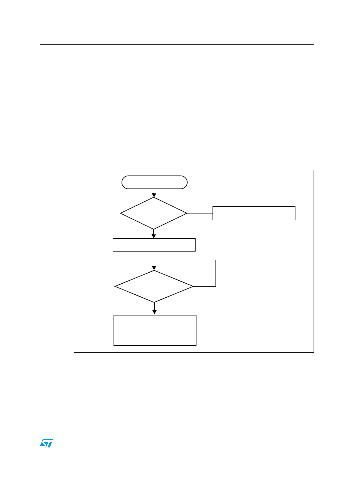
MCU reset
Enter IAP
mode?
IAP initialization
No
Ye s
IAP
Request ?
Receive binary image and
program it into user Flash
area
No
Ye s
Execute application code
1 IAP overview
1.1 Theory of operation
In-Application Programming (IAP) is a means of upgrading firmware in the field using the
MCU communication interfaces like UART, USB, CAN, Ethernet,etc...
When you boot the microcontroller, you can choose to put it in IAP mode in order to execute
the IAP code or else, in normal mode, start to execute the application code. Both the IAP
code and the application code are reside in the embedded Flash memory of the
microcontroller. Usually the IAP code is stored in the first pages of the MCU Flash, and the
user application code occupies the remaining Flash area.
The IAP operation flow is described in the following figure:
Figure 1. IAP operation flow
1.2 IAP using the MCU’s Ethernet interface
When it is available, Ethernet is often the preferred interface for implementing IAP capability
in an embedded application. The advantages are:
● High speed communication interface (10/100Mbit/s)
● Remote programming through the network (LAN or WAN)
● Standardized application protocols on top of the TCP/IP stack that can be used for
implementing the IAP like: FTP, TFTP, HTTP,...
Doc ID 17570 Rev 1 3/18
Page 4

IAP overview AN3226
1.3 Implementing IAP over Ethernet on the STM32F107
This application note describes two solutions that implement IAP for the STM32F107 using
the Ethernet communication peripheral:
● IAP using TFTP (Trivial File Transfer Protocol)
● IAP using HTTP (Hypertext Transfer Protocol)
Both solutions run on top of the LwIP stack (v1.3.1) which is a light-weight implementation of
the TCP/IP protocol suite.
1.3.1 IAP method using TFTP
The IAP method using TFTP, is widely used in embedded applications that require a
firmware upgrade capability (for example in embedded Linux bootloaders).
TFTP is a simple file transfer protocol working on top of the UDP transport layer and it is
mainly intended to be used on a LAN environment. It is based on a client/server
architecture, where a client will request a file transfer (read or write operation) from a file
server.
In our case, a simple TFTP server is implemented on top of the LwIP stack, this server only
processes write requests coming from a PC TFTP client.
1.3.2 IAP method using HTTP
Firmware upgrade through HTTP protocol is less common than with TFTP, but it can be an
useful solution, when remote programming over the Internet is needed. In this case TCP
transport protocol is needed to ensure optimum operation.
HTTP which works on top of TCP, offers a way of sending a binary file from a web client
(example: Mozilla Firefox or Microsoft Internet Explorer) using HTML Forms, it is called
HTTP File-upload (RFC 1867).
The next sections of this document, give more details about the implementation of both IAP
methods and an explanation of how to use the software.
4/18 Doc ID 17570 Rev 1
Page 5
AN3226 IAP using TFTP
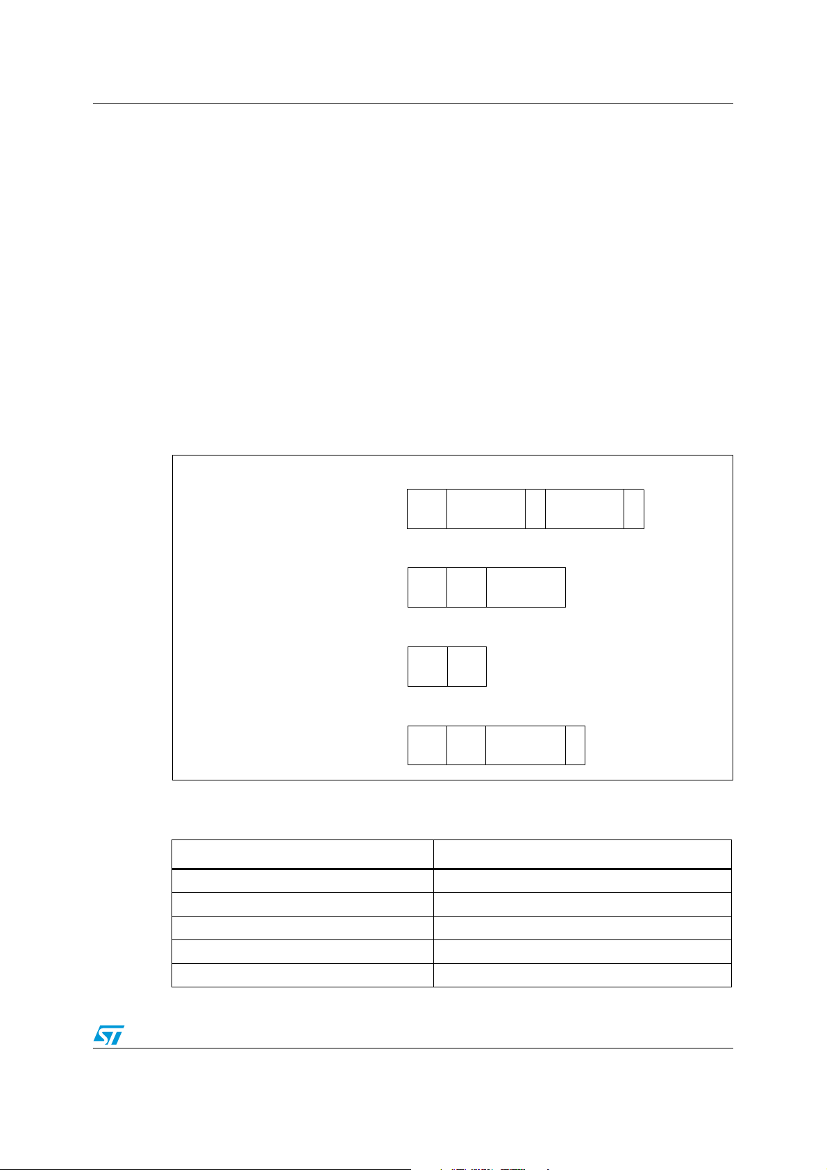
2 bytes String 1 byte String 1 byte
Opcode File name 0 Mode 0
Opcode Block# Data
2 bytes 2 bytes n bytes
2 bytes 2 bytes
Opcode Block#
2 bytes 2 bytes String 1 byte
Opcode
Error
code
Error
message
0
RRQ/WRQ packet
Data packet
ACK packet
Error packet
2 IAP using TFTP
2.1 TFTP overview
Trivial File Transfer Protocol (TFTP) is a simple file transfer protocol, working on top of UDP.
A file transfer is initiated from a TFTP client which sends a Read or Write request to a TFTP
server.
When the server acknowledges the request, file data transfers start. The data is sent in fixed
size blocks (for example in blocks of 512 bytes).
Each transferred data block must be acknowledged by the recepient, before the next block
can be sent. The acknowledge mechanism is based on the block number sent with each
data block.
A data block with less than the fixed block size indicates the termination of the file transfer.
Figure 2 describes the format of the various TFTP packets:
Figure 2. TFTP packets
The TFTP opcodes are listed in Tab le 1 .
Table 1. TFTP opcodes
Opcode Operation
0x1 Read request (RRQ)
0x2 Write request (WRQ)
0x3 Data
0x4 Acknowledgment (ACK)
0x5 Error
Doc ID 17570 Rev 1 5/18
Page 6

IAP using TFTP AN3226
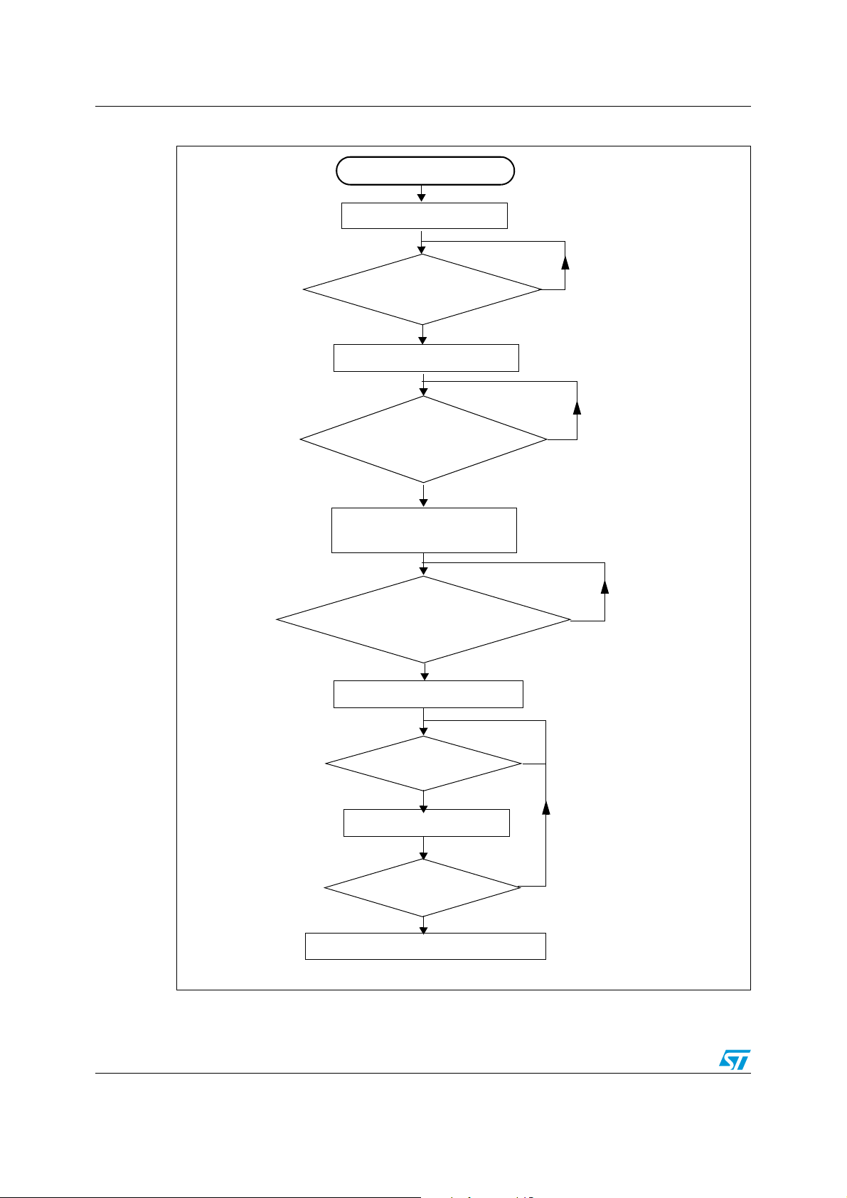
2.2 Implementing IAP for the STM32F107 using TFTP
This IAP implementation consists of a basic TFTP server on top of the LwIP TCP/IP stack.
This server responds to file WRITE requests received from a remote TFTP client (PC).
TFTP READ requests are ignored.
Instead of writing received files to a filesystem which is normally what TFTP is used for, the
server writes the received data blocks into the MCU Flash (in the user Flash area).
Note: In this implementation, the data block size is fixed to 512 bytes.
The following flowchart gives an overview of the IAP operation using TFTP.
6/18 Doc ID 17570 Rev 1
Page 7

AN3226 IAP using TFTP
TFTP server initialization
TFTP Write
request ?
No
Erase the total user Flash area
Send Ack
Data packet
Received?
Write Data block to Flash
Last data Packet
(size<512bytes)
?
Send Ack
End of file transfer
No
No
Enter IAP mode
Figure 3. Flowchart of IAP using TFTP
Doc ID 17570 Rev 1 7/18
Page 8

IAP using TFTP AN3226
2.3 Using the software
In order to test the IAP through TFTP, please ensure you follow these steps:
1. Be sure of the correct jumper settings in the STM3210C_EVAL board (see Tab le 2).
2. In the main.h file, uncomment the option “USE_IAP_TFTP”. Also, depending on your
needs, you can uncomment/comment other options like “USE_DHCP” or “USE_LCD”.
3. Recompile the software. Using the generated map file, be sure that there is no overlap
between the IAP code area (starting from address 0x0) and the user Flash area
starting from address: USER_FLASH_FIRST_PAGE_ADDRESS (defined in main.h).
4. Program the software in the STM32 Flash and run it.
5. To enter IAP mode, press and then release the Reset button while keeping the Key
button pressed.
6. If “USE_LCD” is defined in main.h file then, the LCD screen displays a message
indicating that IAP mode has been entered. Also if DHCP is used (USE_DHCP defined
in main.h), a message is displayed on the LCD screen indicating the success or failure
of DHCP IP address allocation.
7. After IP address assignment (either static or dynamic address), the user can start the
IAP process.
8. On the PC side open the TFTP client (for example TFTPD32), and configure the TFTP
server address (host address in TFTPD32).
9. Browse for a binary image to load in the STM32 Flash (two binary images are provided
as examples in the /project/binary folder).
10. Start a file write request by clicking the “Put” button in the TFTPD32 utility.
11. When USE_LCD is enabled, the progress of the IAP operation is shown on the LCD.
12. At the end of IAP operation, you can reset the evaluation board and run the application
that you have just programmed in the STM32 Flash.
Figure 4. TFTPD32 dialog box
8/18 Doc ID 17570 Rev 1
Page 9

AN3226 IAP using HTTP
3 IAP using HTTP
3.1 HTTP file upload overview
File upload using HTTP is defined in RFC1867. This method of uploading files is based on
HTML forms. To send raw binary data, the HTML POST method is used instead of the GET.
The following is an example of HTML code for implementing form-based file upload:
<form action ="/upload.cgi" enctype="multipart/form-data" method="post">
<p>Please specify a binary file to upload into STM32F107 flash:
<br>
<input type="file" name="datafile" size="40">
</p>
<div>
<input type="submit" value="Upload">
</div></form>
Figure 5. Browser view of the file upload HTML form
The user can browse to select a binary file to upload, and then press the upload button to
send it.
Depending on the file size, the data is sent in consecutive TCP segments to the webserver.
Note: Before sending the file data, the webclient send HTTP header data containing information
such as the file name, the content length, etc... some of which must be parsed by the
webserver.
Different webclients do not always have the same HTTP header format. Figure 6 shows
Internet Explorer HTTP header formatting for the POST request. Figure 7 shows the Mozilla
Firefox HTTP header formatting.
The http webserver must handle these different formats.
Doc ID 17570 Rev 1 9/18
Page 10

IAP using HTTP AN3226
Figure 6. IE6 HTTP header format
Figure 7. Mozilla Firefox HTTP header format
10/18 Doc ID 17570 Rev 1
Page 11

AN3226 IAP using HTTP
3.2 Implementing IAP using HTTP on the STM32F107
This IAP implementation consists of a simple HTTP webserver on top of the LwIP stack.
When typing the STM32 IP address on a browser, a login webpage is shown as in Figure 8.
The aim of this login webpage is to restrict access to the IAP file upload only to authorized
users.
Figure 8. Login webpage
The user has to enter a correct userID and password (pre-defined in main.h file) and click
the Login button. A file upload webpage is then loaded (see Figure 5).
Note: 1 The default userID is: “user “and password is “stm32”.
2 If the userID or password is incorrect, the login webpage will be reloaded.
After a successful login, you can browse to select the binary file to be loaded into STM32
Flash.
Note: 1 It is up to the user to ensure that the binary file size does not exceed the total size of the
STM32 user Flash area.
When clicking the Upload button (see Figure 5), a POST request is sent to the server. At this
moment the server starts erasing all the user Flash area and waits for the binary file raw
data. The received data will be then written into the user Flash area.
Please note that the total length of the data to be received is extracted from the HTTP
header data sent at the beginning of the transfer.
At the end of IAP operation, a webpage is loaded to indicate the success of IAP operation, It
displays a button which allows you to reset the MCU.
Figure 9. File Upload Done webpage
The following flowchart summarizes the IAP method using HTTP.
Doc ID 17570 Rev 1 11/18
Page 12
IAP using HTTP AN3226
HTTP server initialization
Index page
requested?
No
HTML POST
request received for
file upload?
Erase the total user Flash area
Raw data
received?
Write data into Flash
No
Enter IAP mode
Correct
userID/password
submitted?
Index page sent to webclient
No
File upload page sent to
webclient
No
No
All data
received?
Upload_done page sent to webclient
Figure 10. Flowchart of IAP using HTTP
12/18 Doc ID 17570 Rev 1
Page 13

AN3226 IAP using HTTP
3.3 Using the software
In order to test the IAP using HTTP, please follow these steps
1. Be sure of the correct jumper settings in the STM3210C_EVAL board (see Ta bl e 2).
2. In the main.h file, uncomment option “USE_IAP_HTTP”, also depending on your needs
you can uncomment/comment other options like “USE_DHCP” or “USE_LCD”.
3. Recompile the software. Using the generated map file, be sure that there is no overlap
between the IAP code area (starting from address 0x0) and the user Flash area
starting from address: USER_FLASH_FIRST_PAGE_ADDRESS
4. Program the software into STM32 Flash and run it.
5. To enter IAP mode, press then release the Reset button while keeping the Key button
pressed.
6. If “USE_LCD” is defined in main.h file then, the LCD screen displays a message
indicating that IAP mode has been entered. Also in the case of using DHCP
(USE_DHCP defined in main.h), a message is displayed on the LCD screen indicating
the success or failure of DHCP IP address allocation.
7. After IP address assignment (either static or dynamic address), the user can start the
IAP process.
8. Open a webclient (Mozilla Firefox or Microsoft Internet Explorer) and enter the STM32
IP address.
9. A login webpage will be shown. In the UserID field enter “user” and in the Password
field enter “stm32” then press the Login button.
10. The fileupload.html webpage is then loaded. Browse for a binary image to be loaded
into STM32 Flash then press the Upload button in order to start the IAP process.
11. When USE_LCD is enabled, the progress of the IAP operation is shown on LCD.
12. At the end of the IAP operation, a new webpage is loaded indicating the success of the
file upload operation.
13. You can press the “RESET MCU” button to reset the MCU and run the application that
you have just programmed in the STM32 Flash.
(defined in main.h).
Note: Please note that the software was tested with the following webclients: MSIE6, MSIE8 and
Mozilla Firefox 3.6.
3.4 Known limitations
3.4.1 Extra bytes added to binary file
A random boundary tag (no larger than 72 bytes according to RFC 1521) is added to the
end of the uploaded binary file by the internet browser (MSIE or Mozilla Firefox). In the
current version of the IAP software, this boundary tag is not removed and is stored in the
Flash if sufficient space is available. If space is not sufficient, any extra byte is simply not
written in the Flash and no error is returned.
Doc ID 17570 Rev 1 13/18
Page 14

Environment AN3226
4 Environment
4.1 MAC and IP address settings
The MAC and IP address setting is done in file main.h.
The default MAC address is fixed to : 00:00:00:00:00:02
The IP address can be set either as a static address or as a dynamic address, assigned by
a DHCP server. The default static IP address is: 192.168.0.10
You can select DHCP mode by enabling USE_DHCP in main.h file.
Note that if you choose to configure the IP address by DHCP and the application does not
find a DHCP server on the network to which it is already connected, the IP address is then
automatically set to the static address (192.168.0.10).
4.2 Jumper settings on the STM3210C_EVAL board
In order to run the software, you need to configure the STM3210C_EVAL board as shown in
the following table.
You need to select between MII and RMII configuration in the stm32f107.c file.
For example, to select the RMII mode:
//#define MII_MODE
#define RMII_MODE
For MII mode, the PHY clock is taken from the external crystal, while for RMII mode, the
clock is provided by the STM32 via the MCO pin.
Table 2. Jumper configurations
Jumper MII mode configuration RMII mode configuration
JP2 Not connected Connected
JP3 2-3 1-2
JP4 1-2 2-3
JP11 2-3
JP12 2-3
JP13 2-3
JP14 1-2
14/18 Doc ID 17570 Rev 1
Page 15

AN3226 Environment
4.3 Software file organization
The project source files are described in the following table:
Table 3. File organization
File name Description
main.c Main application file
main.h Main configuration file
httpserver.c /.h HTTP server implementation
tftpserver.c /.h TFTP server implementation
flash_if.c /.h High level flash access functions
netconf.c /.h High level ethernet interface functions
stm32f107.c /.h STM32F107C_Eval board bsp functions
stm32f10x_it.c /.h Interrupt handler
fsdata.c HTML files as a ROM filesystem
lwipopts.h LwIP configuratiion options
Note: The table does not show the files used from the standard firmware library and the LwIP
stack.
4.4 Code size measurements
The following table gives some code size measurements made with different configuration
options in main.h file.
Table 4. Code size Vs Configuration options
Code size (bytes) USE_IAP_TFTP USE_IAP_HTTP USE_LCD USE_DHCP
12588 x
25504 x
23532 x x x
36128 x x x
Note: The software is compiled using IAR EWARM v5.41, with high optimization for code size.
4.5 Building an image for IAP
In order to build an image for IAP (to be loaded using the IAP software), please ensure that:
Doc ID 17570 Rev 1 15/18
Page 16

Environment AN3226
1. The vector table start address is configured as the start address of the user Flash area.
You can do this using the std library function: NVIC_SetVectorTable
2. The software is compiled/linked to run starting from the start address of the user Flash
area.
3. The compiled software size does not exceed the total user Flash area
For your reference, a software example is included in AN2557: ”STM32F10xxx inapplication programming using the USART”.
16/18 Doc ID 17570 Rev 1
Page 17

AN3226 Revision history
5 Revision history
Table 5. Document revision history
Date Revision Changes
26-Jul-2010 1 Initial release.
Doc ID 17570 Rev 1 17/18
Page 18

AN3226
Please Read Carefully:
Information in this document is provided solely in connection with ST products. STMicroelectronics NV and its subsidiaries (“ST”) reserve the
right to make changes, corrections, modifications or improvements, to this document, and the products and services described herein at any
time, without notice.
All ST products are sold pursuant to ST’s terms and conditions of sale.
Purchasers are solely responsible for the choice, selection and use of the ST products and services described herein, and ST assumes no
liability whatsoever relating to the choice, selection or use of the ST products and services described herein.
No license, express or implied, by estoppel or otherwise, to any intellectual property rights is granted under this document. If any part of this
document refers to any third party products or services it shall not be deemed a license grant by ST for the use of such third party products
or services, or any intellectual property contained therein or considered as a warranty covering the use in any manner whatsoever of such
third party products or services or any intellectual property contained therein.
UNLESS OTHERWISE SET FORTH IN ST’S TERMS AND CONDITIONS OF SALE ST DISCLAIMS ANY EXPRESS OR IMPLIED
WARRANTY WITH RESPECT TO THE USE AND/OR SALE OF ST PRODUCTS INCLUDING WITHOUT LIMITATION IMPLIED
WARRANTIES OF MERCHANTABILITY, FITNESS FOR A PARTICULAR PURPOSE (AND THEIR EQUIVALENTS UNDER THE LAWS
OF ANY JURISDICTION), OR INFRINGEMENT OF ANY PATENT, COPYRIGHT OR OTHER INTELLECTUAL PROPERTY RIGHT.
UNLESS EXPRESSLY APPROVED IN WRITING BY AN AUTHORIZED ST REPRESENTATIVE, ST PRODUCTS ARE NOT
RECOMMENDED, AUTHORIZED OR WARRANTED FOR USE IN MILITARY, AIR CRAFT, SPACE, LIFE SAVING, OR LIFE SUSTAINING
APPLICATIONS, NOR IN PRODUCTS OR SYSTEMS WHERE FAILURE OR MALFUNCTION MAY RESULT IN PERSONAL INJURY,
DEATH, OR SEVERE PROPERTY OR ENVIRONMENTAL DAMAGE. ST PRODUCTS WHICH ARE NOT SPECIFIED AS "AUTOMOTIVE
GRADE" MAY ONLY BE USED IN AUTOMOTIVE APPLICATIONS AT USER’S OWN RISK.
Resale of ST products with provisions different from the statements and/or technical features set forth in this document shall immediately void
any warranty granted by ST for the ST product or service described herein and shall not create or extend in any manner whatsoever, any
liability of ST.
ST and the ST logo are trademarks or registered trademarks of ST in various countries.
Information in this document supersedes and replaces all information previously supplied.
The ST logo is a registered trademark of STMicroelectronics. All other names are the property of their respective owners.
© 2010 STMicroelectronics - All rights reserved
STMicroelectronics group of companies
Australia - Belgium - Brazil - Canada - China - Czech Republic - Finland - France - Germany - Hong Kong - India - Israel - Italy - Japan -
Malaysia - Malta - Morocco - Philippines - Singapore - Spain - Sweden - Switzerland - United Kingdom - United States of America
www.st.com
18/18 Doc ID 17570 Rev 1
 Loading...