

Page 1

AN3225
Application note
Audio software codec for the STM8L15xxx
Introduction
This application note describes a simple and easy-to-use solution to help design and
develop products with an audio output, for example, toys, alarms, door bells, and white
goods.
Audio data generally require the storage of a lot of memory. However, the memory space
needed to preserve such data can be reduced by compressing the audio data via a
specified compression method. Processing these data is usually a complex task requiring
powerful microcontrollers such as DSP or audio chip. Normally, 8-bit microcontrolles do not
offer either a large memory or a high computing performance.
The software solution offered in this application note reconstructs audio signals from
compressed samples. A simple audio codec based on an adaptive differential pulse coded
modulation (ADPCM) algorithm is used and advantage is taken of the advanced STM8L
core with its 3-staged pipeline and 16 MIPS peak performance.
The digital samples are converted to an analog signal by an on-chip, 12-bit, digital-to-analog
converter (DAC). This offers good overall audio quality, yet is a cost-effective solution for 8bit microcontroller applications.
The battery-powered application benefits from the ultra low-power consumption of STM8L
microcontrollers.
The example firmware and application hardware design are provided with this application
note to enable easy porting of the offered solution to the final application.
December 2010 Doc ID 17566 Rev 2 1/13
www.st.com
Page 2

Contents AN3225
Contents
1 ADPCM codec . . . . . . . . . . . . . . . . . . . . . . . . . . . . . . . . . . . . . . . . . . . . . . 3
1.1 Adaptive differential pulse coded modulation (ADPCM) . . . . . . . . . . . . . . . 3
1.2 Interactive multimedia association (IMA) ADPCM . . . . . . . . . . . . . . . . . . . 3
1.3 IMA ADPCM decompression . . . . . . . . . . . . . . . . . . . . . . . . . . . . . . . . . . . 4
1.4 IMA ADPCM compression . . . . . . . . . . . . . . . . . . . . . . . . . . . . . . . . . . . . . 5
2 Audio data encoding and storing . . . . . . . . . . . . . . . . . . . . . . . . . . . . . . 6
2.1 Internal Flash memory used for audio data storing . . . . . . . . . . . . . . . . . . 6
2.2 External memory used for audio data storing . . . . . . . . . . . . . . . . . . . . . . 8
3 STM8L audio output using on-chip 12-bit DAC . . . . . . . . . . . . . . . . . . . 9
4 Conclusion . . . . . . . . . . . . . . . . . . . . . . . . . . . . . . . . . . . . . . . . . . . . . . . . 11
5 References . . . . . . . . . . . . . . . . . . . . . . . . . . . . . . . . . . . . . . . . . . . . . . . . 11
6 Revision history . . . . . . . . . . . . . . . . . . . . . . . . . . . . . . . . . . . . . . . . . . . 12
2/13 Doc ID 17566 Rev 2
Page 3

AN3225 ADPCM codec
1 ADPCM codec
1.1 Adaptive differential pulse coded modulation (ADPCM)
ADPCM is a fixed length codeword audio codec which reduces redundant information from
audio waveforms. The information core is separated from the correlated waveform samples
by encoding differences between the current samples and the predicted ones. As the
correlation between consecutive audio samples is generally high, this method is reasonably
effective and preserves good audio quality. The ADPCM codec, which is based on coding
waveforms in time domains, is much less complex than codecs based on voice perception
(vocoders) that operate in frequency domains. For these reasons, the ADPCM codec is the
best choice for the audio output on 8-bit microcontrollers.
The ADPCM algorithm has been developed for speech coding. It is implemented in several
steps and is used in telephone systems like ITU-T G.726 (covering CCITT G.721 and G.723
standards). G.726 and similar telecommunication codecs, offer several advanced features
which are necessary for successful transmission and streaming. Such features include
synchronous coding adjustment, tone detection to carry data modem signals, adaptated
speed control, and recovery from transmission error conditions. These features lead to
additional algorithm complexity which either requires the use of a digital signal processor
(DSP) or lowering the encoding/decoding sample rate. Such features do not bring many
additional benefits to the microcontroller for coding/decoding the audio or speech signals.
Less complex alternatives can be found.
1.2 Interactive multimedia association (IMA) ADPCM
The IMA
different computers platforms, for example in Microsoft® Sound Recorder or Apple®
QuickTime® player. It was originally offered by Intel/DVI® as an open standard for use by
the IMA. The reference algorithms and recommended formats were initially developed by
the digital audio technical working group (DATWG) and refined by the digital audio focus
group (DAFG) of the IMA. These groups are no longer active.
The IMA DATWG reference algorithm is less complex than the G.726 algorithm. The number
of encoding/decoding CPU cycles needed is reduced by using fixed prediction and by
replacing complex floating point mathematical operations by look-up tables. The
implementation of the ADPCM codec presented in this application note is compatible with
the IMA reference algorithm published by the IMA DATWG/DAFG in the “Recommended
Practices for Enhancing Digital Audio Compatibility in Multimedia Systems”, revision 3.00
(see References).
(a)
ADPCM codec is one such alternative solution. This codec is widely used across
a. IMA is a computer/audio/video industry trade association that has worked to promote multimedia application
development.
Doc ID 17566 Rev 2 3/13
Page 4
ADPCM codec AN3225
3
Q
3
D
3
,
3
P
Q
)NVERSEQUANTIZER
0REDICTOR3TEPSIZEADAPTOR
AI
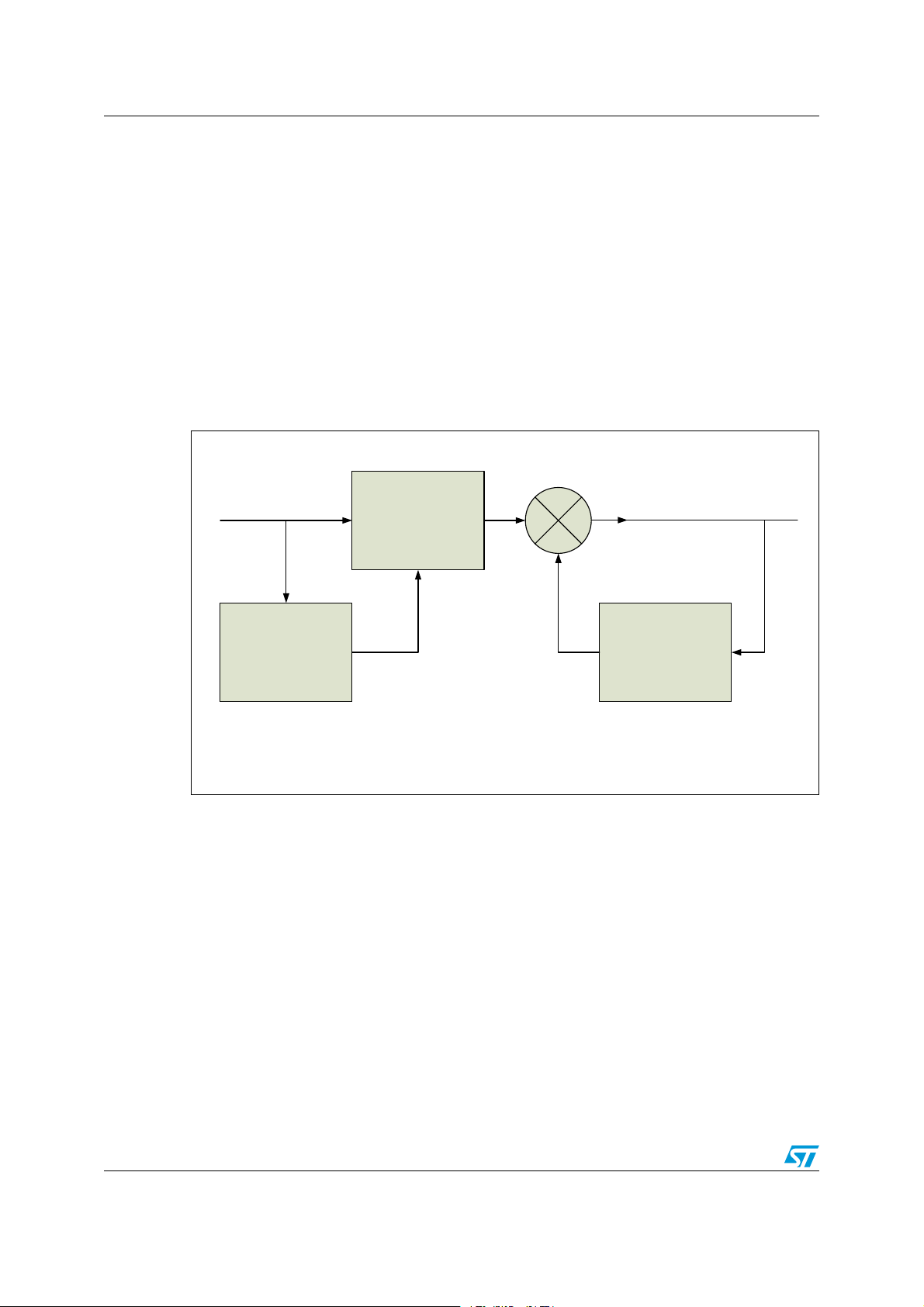
1.3 IMA ADPCM decompression
The IMA ADPCM decompression algorithm compresses samples which are stored as 4-bit
signed two’s complement values. The result is decompressed samples in linear 16-bit two’s
complement format.
The input sample (S
obtain a difference (S
) is dequantized using an inverse quantizer with an adapted step (q) to
q
). The step size is adapted by using a lookup table approximating to
d
an exponential function. The vector pointing to the lookup table is adjusted according to the
magnitude of S
subtracted to S
predicted sample (S
previous output value. The decoder preconditions are that S
. To reduce quantization errors, one half of the step size is always added or
q
. The resulting decompressed linear sample is the sum of Sd and the
d
). As Sp is a simple zero order hold function, Sd is simply added to the
p
is cleared and that the
p
quantization step is set to the smallest one.
Figure 1. ADPCM decoder
4/13 Doc ID 17566 Rev 2
Page 5

AN3225 ADPCM codec
)NVERSEQUANTIZER3TEPSIZEADAPTOR
0REDICTOR
1UANTIZER
qq
3
P
3
IN
3
,
D
3
D
3
Q
AI
1.4 IMA ADPCM compression
The IMA ADPCM compression algorithm encoder calculates a difference (d) between a 16bit input linear sample (S
to a 4-bit compressed output sample (S
step is the same one as that used by the decoder. Figure 2 provides a flowchart of the
ADPCM encoder. It also shows the decoder building blocks with the functionality described
in Section 1.3 (see filled light green components). As the encoder covers identical blocks to
the decoder and produces identical results, there is no need to store prediction information.
The quantized difference is the only core information about the coded samples which needs
to be stored or transmitted.
Figure 2. ADPCM encoder
) and a predicted linear sample (SL). The difference is quantized
in
) by using an adapted quantization step (q). This
q
Doc ID 17566 Rev 2 5/13
Page 6

Audio data encoding and storing AN3225
Memory samplerate length 2=
2 Audio data encoding and storing
The IMA ADPCM codec is quite popular on PC platforms and a wide range of audio
software with different capabilities to process and encode audio data is available. The
problematic part of encoded file storage is the file format of the ADPCM bitstream as it is not
standardized (see “IMA Digital Audio Focus and Technical Working Group” in Section 5:
References). On 8-bit microcontrollers, raw data without any formatting is preferred to obtain
the easiest manipulation with the coded audio file.
On the Microsoft Windows® platform, a WAVEform (WAV) audio data container is often
used to store linear pulse coded modulation (PCM) data. The WAV can also be used to
store IMA ADPCM audio data. To use the WAV for storing audio bitstream, a WAV parser
has to be implemented in the microcontroller decoding firmware. This is to unpack raw data
so that they can be decompressed. The WAV parser increases the complexity and size of
the application and does not bring many additional benefits to an 8-bit system.
Fortunately, there is software available to store coded audio bitstream directly as raw data.
An example includes the Sound eXchange (SOX) command-line application for audio
manipulation distributed under a GNU general purpose license (http://sox.sourceforge.net).
SOX is able to:
● Resample input audio data to any target frequency
● Encode such data in IMA ADPCM format
● Save output bitstream as unformatted raw data
The example command below shows the input parameters used to resample data to:
● Target frequency 15625 Hz
● Reduce volume by -12 dB
● Compress data by using the IMA ADPCM codec
sox inputfilename -r 15625 outputfilename.ima gain -12
Various input file formats can be used, including PCM WAV, MP3, MP4, OGG, FLAC, and
many others. See the SOX documentation for further details.
2.1 Internal Flash memory used for audio data storing
The internal memory of STM8 can be used to store short audio waveforms. One 16-bit PCM
sample takes half a byte when compressed by IMA ADPCM codec. The memory
requirement can be evaluated using Equation 1.
Equation 1
For example,
memory.
The audio data can be saved to the internal memory by using “in-application programming”
(IAP) or the bootloader. See the AN2659 (STM8 in-application programming (IAP) using a
customized user-bootloader) and UM0560 (STM8 bootloader) for more details.
a 5-second ADPCM bitstream with an 8-kHz sample rate uses 20 Kbytes of
6/13 Doc ID 17566 Rev 2
Page 7

AN3225 Audio data encoding and storing
Another way to store audio data to the internal memory is to link audio data arrays with the
compiled code. To include raw data in a project, a binary representation of the data have to
be converted to ASCII format. Any advanced HEX editor is able to export data in this format
which is then readable by ANSI C compilers. The TxD hexa editor (see References) is an
easy-to-use software, with a free license, no restrictions for commercial use, and which can
be freely distributed.
The processing of audio data, which have to be included in a project, consists of loading
binary data into the editor and exporting them as a C source code.
Figure 3. Hexa editor export to
C source code
The output of this operation is a C source file with one array:
unsigned char rawData[10340] = { ...
This declaration has to be modified, using compiler directives, into an array of constants in
the program memory. This is done for the COSMIC compiler as follows:
const @far unsigned char rawData[10340] = { ...
For the Raisonance compiler, the following directive has to be used:
fcode unsigned char rawData[10340] = { ...
For more details, see the firmware project associated with this application note on
www.st.com/mcu.
Doc ID 17566 Rev 2 7/13
Page 8

Audio data encoding and storing AN3225
2.2 External memory used for audio data storing
The micro SD card is used for demonstration purposes in this application note for storing
audio bitstreams. Any other external memory with an interface that is supported by STM8L
can be used instead.
The SD card can be accessed immediately by the operating system if it is formatted by a
supported file system i.e. File Allocation Table (FAT) filing system. If the SD card is FAT
formatted, the microcontroller firmware must also support the FAT file system. Unfortunately,
FAT implementation on an 8-bit microcontroller uses too many resources and the footprint is
too large for a low-cost oriented microcontroller application. Moreover, it is usually not
needed as the audio content of the card is often changed only once. A more convenient way
of putting audio data on the SD card is to use specific software which has an embedded
driver that bypasses the operation and file system drivers, therby allowing direct SD card
access.
A hex editor with such direct access features can be used for modification of the
unformatted SD card content. One of the available and tested hex editors can be found in
Section 5: References (see TxD).
When the compressed ADPCM data is written to the SD card the MCU firmware can directly
read the compressed data samples from the SD card sector by sector. The standard SD
card has a fixed sector size of 512 bytes.
8/13 Doc ID 17566 Rev 2
Page 9

AN3225 STM8L audio output using on-chip 12-bit DAC
DAC
LOWPASS FILTER AMPLIFIER
$!#
!-0,)&)%2
2
#
AI
3 STM8L audio output using on-chip 12-bit DAC
The hardware solution benefits from the STM8L 12-bit DAC with buffered output. Only a few
external components are needed to build an application with audio output. A reconstruction
low pass filter is needed to reduce the high frequency content in the DAC output (see
Figure 4). An audio amplifier is also necessary when boosted power output is required.
Figure 4. DAC output
1. LP = Lowpass filter
The reconstruction filter should be set up as a lowpass filter with a cutoff frequency lower
than half that of the sampling frequency (f
sampling
to sufficiently attenuate the aliased and higher harmonic components present in the output
frequency spectrum of the DAC. The presence of higher harmonic components are caused
by a staircase shaped signal of the on-chip DAC. It has a standard topology output circuit
which implements the zero-order hold function. The higher the band stop attenuation, the
lower the output noise. The order of the lowpass (LP) filter determines the steepness (rolloff) of the frequency characteristic transition from passband to stopband. The order of the
LP filter is determined by the attenuation at the Nyquist frequency (half of the sampling
frequency) and the ratio between the Nyquist frequency and the cutoff frequency. A
common requirement is to keep the noise amplitude over the Nyquist frequency (attenuated
by the filter) well bellow quantization noise.
). The purpose of the reconstruction filter is
Figure 5. DAC output filtered by RC filter
Doc ID 17566 Rev 2 9/13
Page 10

STM8L audio output using on-chip 12-bit DAC AN3225
fc 1 2RC=
The simplest form of the reconstruction filter is the resistor-capacitor (RC) lowpass filter. The
cutoff frequency of the RC circuit, fc, is shown in Equation 2.
Equation 2
The amplitude drop over the cutoff frequency is approximately -6 dB per octave (or -20 dB
per decade). The frequency response of the speaker can bring an additional attenuation of
the high frequency content. However, for high quality audio output it is better to implement a
second order active LP filter providing steeper attenuation of higher frequencies. One
example of an active LP filter design is the ‘Sallen-Key configuration’ design which has a
unity gain operational amplifier (op-amp). For more information about active LP filter
designs, see the LS204 datasheet.
The output of STM8L15xxx DAC can be buffered by on-chip output amplifier to reduce the
output impedance. It can be enabled by setting the BOFF bit in the DAC_CR1 register. An
external audio amplifier should buffer (or be integrated as a part of) the reconstruction filter
to supply a low impedance speaker or to achieve a higher output power.
An example of a reconstruction filter with an output buffer can be found on the STM8L1528EVAL evaluation board. Details including schematics can be found in the UM0784.
10/13 Doc ID 17566 Rev 2
Page 11

AN3225 Conclusion
4 Conclusion
This application note offers a simple and ready-to-use application solution for the STM8L
with good quality audio/speech output.
The solution offered benefits from the STM8L on-chip DAC with a 12-bit resolution and the
advanced low-power modes of the STM8L microcontroller which are aimed at batterypowered applications.
To adequately reduce memory space which allows an audio bitstream to be stored, an IMA
ADPCM codec is implemented. Short audio clips can be stored directly in the internal
program memory. To store long length audio clips, an external memory is needed. The SD
card was used as an example in this application note.
The STM8L audio output solution was developed with the aim to limit external components.
It is suitable for low cost applications.
5 References
IMA Digital Audio Focus and Technical Working Group, Recommended Practices for
Enhancing Digital Audio Compatibility in Multimedia Systems, revision 3.00, October 21,
1992. No longer available on http://www.ima.org.
Maël Hörz, HxD, revision 1.7.7.0 - hexa editor, http://mh-nexus.de.
Doc ID 17566 Rev 2 11/13
Page 12

Revision history AN3225
6 Revision history
Table 1. Document revision history
Date Revision Changes
08-Sep-2010 1 Initial release
06-Dec-2010 2
Section 3: STM8L audio output using on-chip 12-bit DAC:
changed reference to UM0482 to UM0784.
12/13 Doc ID 17566 Rev 2
Page 13

AN3225
Please Read Carefully:
Information in this document is provided solely in connection with ST products. STMicroelectronics NV and its subsidiaries (“ST”) reserve the
right to make changes, corrections, modifications or improvements, to this document, and the products and services described herein at any
time, without notice.
All ST products are sold pursuant to ST’s terms and conditions of sale.
Purchasers are solely responsible for the choice, selection and use of the ST products and services described herein, and ST assumes no
liability whatsoever relating to the choice, selection or use of the ST products and services described herein.
No license, express or implied, by estoppel or otherwise, to any intellectual property rights is granted under this document. If any part of this
document refers to any third party products or services it shall not be deemed a license grant by ST for the use of such third party products
or services, or any intellectual property contained therein or considered as a warranty covering the use in any manner whatsoever of such
third party products or services or any intellectual property contained therein.
UNLESS OTHERWISE SET FORTH IN ST’S TERMS AND CONDITIONS OF SALE ST DISCLAIMS ANY EXPRESS OR IMPLIED
WARRANTY WITH RESPECT TO THE USE AND/OR SALE OF ST PRODUCTS INCLUDING WITHOUT LIMITATION IMPLIED
WARRANTIES OF MERCHANTABILITY, FITNESS FOR A PARTICULAR PURPOSE (AND THEIR EQUIVALENTS UNDER THE LAWS
OF ANY JURISDICTION), OR INFRINGEMENT OF ANY PATENT, COPYRIGHT OR OTHER INTELLECTUAL PROPERTY RIGHT.
UNLESS EXPRESSLY APPROVED IN WRITING BY AN AUTHORIZED ST REPRESENTATIVE, ST PRODUCTS ARE NOT
RECOMMENDED, AUTHORIZED OR WARRANTED FOR USE IN MILITARY, AIR CRAFT, SPACE, LIFE SAVING, OR LIFE SUSTAINING
APPLICATIONS, NOR IN PRODUCTS OR SYSTEMS WHERE FAILURE OR MALFUNCTION MAY RESULT IN PERSONAL INJURY,
DEATH, OR SEVERE PROPERTY OR ENVIRONMENTAL DAMAGE. ST PRODUCTS WHICH ARE NOT SPECIFIED AS "AUTOMOTIVE
GRADE" MAY ONLY BE USED IN AUTOMOTIVE APPLICATIONS AT USER’S OWN RISK.
Resale of ST products with provisions different from the statements and/or technical features set forth in this document shall immediately void
any warranty granted by ST for the ST product or service described herein and shall not create or extend in any manner whatsoever, any
liability of ST.
ST and the ST logo are trademarks or registered trademarks of ST in various countries.
Information in this document supersedes and replaces all information previously supplied.
The ST logo is a registered trademark of STMicroelectronics. All other names are the property of their respective owners.
© 2010 STMicroelectronics - All rights reserved
STMicroelectronics group of companies
Australia - Belgium - Brazil - Canada - China - Czech Republic - Finland - France - Germany - Hong Kong - India - Israel - Italy - Japan -
Malaysia - Malta - Morocco - Philippines - Singapore - Spain - Sweden - Switzerland - United Kingdom - United States of America
www.st.com
Doc ID 17566 Rev 2 13/13
 Loading...