ST AN3212 Application note

AN3212

Application note

3.5 W to 7 W high power factor offline LED driver based on VIPer devices

Introduction

The driving idea behind this application note is to exploit the possibility of implementing an LED power supply module characterized by a high power factor, based on devices from the VIPer family in flyback configuration and with a TSM1052 as a constant current controller.

The other key point is to avoid using high voltage electrolytic capacitors, evaluate the influence of the output bulk electrolytic capacitor on overall performance, and consider its replacement with much smaller ceramic components, eventually implementing a non electrolytic configuration.

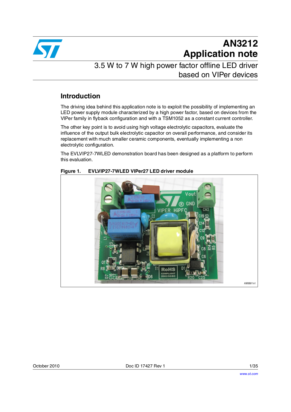
The EVLVIP27-7WLED demonstration board has been designed as a platform to perform this evaluation.

Figure 1. EVLVIP27-7WLED VIPer27 LED driver module

October 2010

Doc ID 17427 Rev 1

1/35

www.st.com

Contents

AN3212


Contents

1

Main characteristics . . . . . . . . . . . . . . . . . . . . . . . . . . . . . . . . . . . . . . . .

. 5


1.1

Initial configuration . . . . . . . . . . . . . . . . . . . . . . . . . . . . . . . . . . . . . . . . . . .

5


1.2

Requirements . . . . . . . . . . . . . . . . . . . . . . . . . . . . . . . . . . . . . . . . . . . . . . .

5

2

Circuit description . . . . . . . . . . . . . . . . . . . . . . . . . . . . . . . . . . . . . . . . . . .

6


2.1

Primary side . . . . . . . . . . . . . . . . . . . . . . . . . . . . . . . . . . . . . . . . . . . . . . . .

6


2.2

Secondary side . . . . . . . . . . . . . . . . . . . . . . . . . . . . . . . . . . . . . . . . . . . . .

9


2.3

Circuit variants . . . . . . . . . . . . . . . . . . . . . . . . . . . . . . . . . . . . . . . . . . . . .

11

3

Waveforms . . . . . . . . . . . . . . . . . . . . . . . . . . . . . . . . . . . . . . . . . . . . . . . .

12


3.1

Input . . . . . . . . . . . . . . . . . . . . . . . . . . . . . . . . . . . . . . . . . . . . . . . . . . . . .

12


3.2

Output . . . . . . . . . . . . . . . . . . . . . . . . . . . . . . . . . . . . . . . . . . . . . . . . . . .

14


3.3

Startup sequence . . . . . . . . . . . . . . . . . . . . . . . . . . . . . . . . . . . . . . . . . . .

15


3.4

Short-circuit protection . . . . . . . . . . . . . . . . . . . . . . . . . . . . . . . . . . . . . . .

16


3.5

Open circuit protection . . . . . . . . . . . . . . . . . . . . . . . . . . . . . . . . . . . . . . .

18

4

Measurements . . . . . . . . . . . . . . . . . . . . . . . . . . . . . . . . . . . . . . . . . . . . .

20


4.1

7.0 W NO EL_CAP configuration . . . . . . . . . . . . . . . . . . . . . . . . . . . . . . .

21


4.2

7.0 W EL_CAP configuration . . . . . . . . . . . . . . . . . . . . . . . . . . . . . . . . . .

24


4.3

EMI filter . . . . . . . . . . . . . . . . . . . . . . . . . . . . . . . . . . . . . . . . . . . . . . . . . .

27


4.4

Thermal maps . . . . . . . . . . . . . . . . . . . . . . . . . . . . . . . . . . . . . . . . . . . . .

28

5

Electrical diagram . . . . . . . . . . . . . . . . . . . . . . . . . . . . . . . . . . . . . . . . . .

29

6

BOM list . . . . . . . . . . . . . . . . . . . . . . . . . . . . . . . . . . . . . . . . . . . . . . . . . .

30

7

7 W transformer specifications . . . . . . . . . . . . . . . . . . . . . . . . . . . . . . .

32


7.1

Mechanical specifications . . . . . . . . . . . . . . . . . . . . . . . . . . . . . . . . . . . . .

32


7.2

Electrical specifications . . . . . . . . . . . . . . . . . . . . . . . . . . . . . . . . . . . . . .

33

8

Revision history . . . . . . . . . . . . . . . . . . . . . . . . . . . . . . . . . . . . . . . . . . .

34

2/35

Doc ID 17427 Rev 1

AN3212

List of figures


List of figures

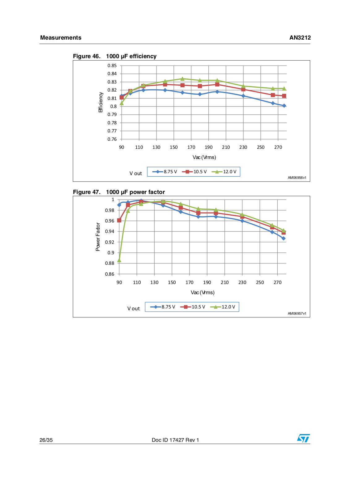
Figure 1. EVLVIP27-7WLED VIPer27 LED driver module. . . . . . . . . . . . . . . . . . . . . . . . . . . . . . . . . . 1 Figure 2. Initial configuration . . . . . . . . . . . . . . . . . . . . . . . . . . . . . . . . . . . . . . . . . . . . . . . . . . . . . . . . 5 Figure 3. Primary side schematic. . . . . . . . . . . . . . . . . . . . . . . . . . . . . . . . . . . . . . . . . . . . . . . . . . . . . 6 Figure 4. IDlim vs Rlim - VIPer17. . . . . . . . . . . . . . . . . . . . . . . . . . . . . . . . . . . . . . . . . . . . . . . . . . . . . 7 Figure 5. IDlim vs Rlim - VIPer27. . . . . . . . . . . . . . . . . . . . . . . . . . . . . . . . . . . . . . . . . . . . . . . . . . . . . 7 Figure 6. No feedback on FB pin . . . . . . . . . . . . . . . . . . . . . . . . . . . . . . . . . . . . . . . . . . . . . . . . . . . . . 8 Figure 7. Feedback on FB pin . . . . . . . . . . . . . . . . . . . . . . . . . . . . . . . . . . . . . . . . . . . . . . . . . . . . . . . 8 Figure 8. Feedback voltage V_fb vs. VAC and Vout . . . . . . . . . . . . . . . . . . . . . . . . . . . . . . . . . . . . . . 8 Figure 9. Secondary side equivalent schematic . . . . . . . . . . . . . . . . . . . . . . . . . . . . . . . . . . . . . . . . . 9 Figure 10. V_drain, I_drain at Vin= 75 V . . . . . . . . . . . . . . . . . . . . . . . . . . . . . . . . . . . . . . . . . . . . . . . 12 Figure 11. V_drain, I_drain at Vin= 100 V . . . . . . . . . . . . . . . . . . . . . . . . . . . . . . . . . . . . . . . . . . . . . . 12 Figure 12. V_drain, I_drain at Vin= 120 V . . . . . . . . . . . . . . . . . . . . . . . . . . . . . . . . . . . . . . . . . . . . . . 12 Figure 13. V_drain, I_drain at Vin= 162 V . . . . . . . . . . . . . . . . . . . . . . . . . . . . . . . . . . . . . . . . . . . . . . 12 Figure 14. V_drain, I_drain at Vin= 254 V . . . . . . . . . . . . . . . . . . . . . . . . . . . . . . . . . . . . . . . . . . . . . . 13 Figure 15. V_drain, I_drain at Vin= 325 V . . . . . . . . . . . . . . . . . . . . . . . . . . . . . . . . . . . . . . . . . . . . . . 13 Figure 16. V_drain, I_drain at Vin= 391 V . . . . . . . . . . . . . . . . . . . . . . . . . . . . . . . . . . . . . . . . . . . . . . 13 Figure 17. V_drain, I_drain at Vin= 50 V . . . . . . . . . . . . . . . . . . . . . . . . . . . . . . . . . . . . . . . . . . . . . . . 13 Figure 18. Vin and Iin at Vin = 230 VAC . . . . . . . . . . . . . . . . . . . . . . . . . . . . . . . . . . . . . . . . . . . . . . . 14 Figure 19. Vin and Iin at Vin = 115 VAC . . . . . . . . . . . . . . . . . . . . . . . . . . . . . . . . . . . . . . . . . . . . . . . 14 Figure 20. V_out, I_out at Vin = 230 VAC, no El_cap . . . . . . . . . . . . . . . . . . . . . . . . . . . . . . . . . . . . . 14 Figure 21. V_out, I_out at Vin = 115 VAC, no El_cap . . . . . . . . . . . . . . . . . . . . . . . . . . . . . . . . . . . . . 14 Figure 22. V_out, I_out at Vin = 230 VAC, 1000 µF El_cap. . . . . . . . . . . . . . . . . . . . . . . . . . . . . . . . . 15 Figure 23. V_out, I_out at Vin = 115 VAC,1000 µF El_cap . . . . . . . . . . . . . . . . . . . . . . . . . . . . . . . . . 15 Figure 24. Startup sequence at Vin = 230 VAC, no El_cap . . . . . . . . . . . . . . . . . . . . . . . . . . . . . . . . . 15 Figure 25. Startup sequence at Vin = 115 VAC, no El_cap . . . . . . . . . . . . . . . . . . . . . . . . . . . . . . . . . 15 Figure 26. Startup sequence at Vin = 230 VAC, 1000 µF El_cap . . . . . . . . . . . . . . . . . . . . . . . . . . . . 16 Figure 27. Startup sequence at Vin = 115 VAC, 1000 µF El_cap . . . . . . . . . . . . . . . . . . . . . . . . . . . . 16 Figure 28. Short-circuit protection . . . . . . . . . . . . . . . . . . . . . . . . . . . . . . . . . . . . . . . . . . . . . . . . . . . . 17 Figure 29. Short circuit application. . . . . . . . . . . . . . . . . . . . . . . . . . . . . . . . . . . . . . . . . . . . . . . . . . . . 17 Figure 30. Short circuit removal . . . . . . . . . . . . . . . . . . . . . . . . . . . . . . . . . . . . . . . . . . . . . . . . . . . . . . 17 Figure 31. Open circuit protection Vin = 277 VAC . . . . . . . . . . . . . . . . . . . . . . . . . . . . . . . . . . . . . . . . 18 Figure 32. Open circuit protection Vin = 90 VAC . . . . . . . . . . . . . . . . . . . . . . . . . . . . . . . . . . . . . . . . . 18 Figure 33. Open circuit application . . . . . . . . . . . . . . . . . . . . . . . . . . . . . . . . . . . . . . . . . . . . . . . . . . . 19 Figure 34. Open circuit removal. . . . . . . . . . . . . . . . . . . . . . . . . . . . . . . . . . . . . . . . . . . . . . . . . . . . . . 19 Figure 35. Test setup . . . . . . . . . . . . . . . . . . . . . . . . . . . . . . . . . . . . . . . . . . . . . . . . . . . . . . . . . . . . . . 20 Figure 36. NO_El_Cap output voltage (average). . . . . . . . . . . . . . . . . . . . . . . . . . . . . . . . . . . . . . . . . 21 Figure 37. NO_El_Cap output current (average) . . . . . . . . . . . . . . . . . . . . . . . . . . . . . . . . . . . . . . . . . 21 Figure 38. NO_El_Cap output current (peak) . . . . . . . . . . . . . . . . . . . . . . . . . . . . . . . . . . . . . . . . . . . 22 Figure 39. NO_El_Cap output power. . . . . . . . . . . . . . . . . . . . . . . . . . . . . . . . . . . . . . . . . . . . . . . . . . 22 Figure 40. NO_El_Cap efficiency. . . . . . . . . . . . . . . . . . . . . . . . . . . . . . . . . . . . . . . . . . . . . . . . . . . . . 23 Figure 41. NO_El_Cap power factor . . . . . . . . . . . . . . . . . . . . . . . . . . . . . . . . . . . . . . . . . . . . . . . . . . 23 Figure 42. 1000 µF output voltage (average). . . . . . . . . . . . . . . . . . . . . . . . . . . . . . . . . . . . . . . . . . . . 24 Figure 43. 1000 µF output current (average) . . . . . . . . . . . . . . . . . . . . . . . . . . . . . . . . . . . . . . . . . . . . 24 Figure 44. 1000 µF output current (peak) . . . . . . . . . . . . . . . . . . . . . . . . . . . . . . . . . . . . . . . . . . . . . . 25 Figure 45. 1000 µF output power. . . . . . . . . . . . . . . . . . . . . . . . . . . . . . . . . . . . . . . . . . . . . . . . . . . . . 25 Figure 46. 1000 µF efficiency. . . . . . . . . . . . . . . . . . . . . . . . . . . . . . . . . . . . . . . . . . . . . . . . . . . . . . . . 26 Figure 47. 1000 µF power factor . . . . . . . . . . . . . . . . . . . . . . . . . . . . . . . . . . . . . . . . . . . . . . . . . . . . . 26 Figure 48. EMI (PI filter) 230 VAC . . . . . . . . . . . . . . . . . . . . . . . . . . . . . . . . . . . . . . . . . . . . . . . . . . . . 27

Doc ID 17427 Rev 1

3/35

List of figures

AN3212


Figure 49. EMI (PI filter) 115 VAC . . . . . . . . . . . . . . . . . . . . . . . . . . . . . . . . . . . . . . . . . . . . . . . . . . . . 27 Figure 50. EMI (L + PI filter) 230 VAC . . . . . . . . . . . . . . . . . . . . . . . . . . . . . . . . . . . . . . . . . . . . . . . . . 27 Figure 51. EMI (L + PI filter) 115 VAC . . . . . . . . . . . . . . . . . . . . . . . . . . . . . . . . . . . . . . . . . . . . . . . . . 27 Figure 52. Thermal map at 90 VAC . . . . . . . . . . . . . . . . . . . . . . . . . . . . . . . . . . . . . . . . . . . . . . . . . . . 28 Figure 53. Thermal map at 115 VAC . . . . . . . . . . . . . . . . . . . . . . . . . . . . . . . . . . . . . . . . . . . . . . . . . . 28 Figure 54. Thermal map at 230 VAC . . . . . . . . . . . . . . . . . . . . . . . . . . . . . . . . . . . . . . . . . . . . . . . . . . 28 Figure 55. Thermal map at 277 VAC . . . . . . . . . . . . . . . . . . . . . . . . . . . . . . . . . . . . . . . . . . . . . . . . . . 28 Figure 56. Electrical diagram . . . . . . . . . . . . . . . . . . . . . . . . . . . . . . . . . . . . . . . . . . . . . . . . . . . . . . . . 29 Figure 57. Coil former mechanical drawing . . . . . . . . . . . . . . . . . . . . . . . . . . . . . . . . . . . . . . . . . . . . . 32 Figure 58. Transformer assembly . . . . . . . . . . . . . . . . . . . . . . . . . . . . . . . . . . . . . . . . . . . . . . . . . . . . 32 Figure 59. Transformer electrical drawing . . . . . . . . . . . . . . . . . . . . . . . . . . . . . . . . . . . . . . . . . . . . . . 33

4/35

Doc ID 17427 Rev 1

AN3212

Main characteristics


1 Main characteristics

1.1Initial configuration

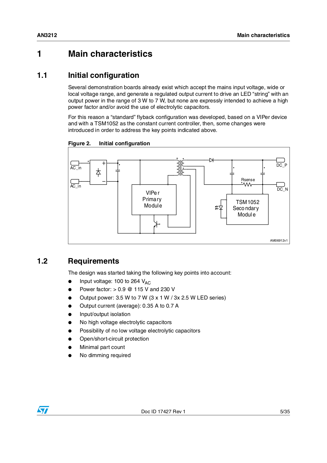
Several demonstration boards already exist which accept the mains input voltage, wide or local voltage range, and generate a regulated output current to drive an LED “string” with an output power in the range of 3 W to 7 W, but none are expressly intended to achieve a high power factor and/or avoid the use of electrolytic capacitors.

For this reason a “standard” flyback configuration was developed, based on a VIPer device and with a TSM1052 as the constant current controller, then, some changes were introduced in order to address the key points indicated above.

Figure 2. Initial configuration

!#?IN


$#?0


2SENSE

!#?IN


$#?.


6)0E R


0RIMARY

43-


-ODULE


3ECONDARY


-ODULE


!-V

1.2Requirements

The design was started taking the following key points into account:

Input voltage: 100 to 264 VAC

Power factor: > 0.9 @ 115 V and 230 V

Output power: 3.5 W to 7 W (3 x 1 W / 3x 2.5 W LED series)

Output current (average): 0.35 A to 0.7 A

Input/output isolation

No high voltage electrolytic capacitors

Possibility of no low voltage electrolytic capacitors

Open/short-circuit protection

Minimal part count

No dimming required

Doc ID 17427 Rev 1

5/35

Circuit description

AN3212


2 Circuit description

2.1Primary side

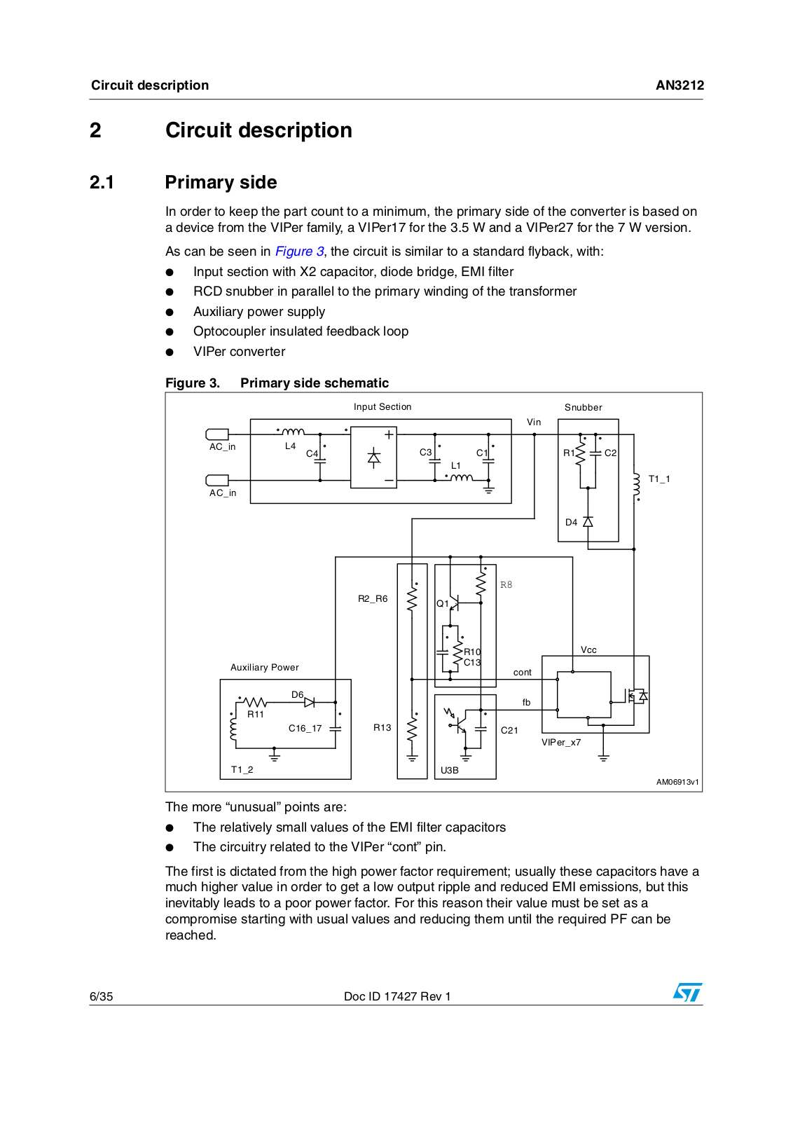
In order to keep the part count to a minimum, the primary side of the converter is based on a device from the VIPer family, a VIPer17 for the 3.5 W and a VIPer27 for the 7 W version.

As can be seen in Figure 3, the circuit is similar to a standard flyback, with:

Input section with X2 capacitor, diode bridge, EMI filter

RCD snubber in parallel to the primary winding of the transformer

Auxiliary power supply

Optocoupler insulated feedback loop

VIPer converter

Figure 3. Primary side schematic


)NPUTT3ECTION


3NUBBER


6IN


!#?IN

,

#

#

2

#


#


,


4 ?

!#?IN


$


2 ?2


5


1


2

6CC


!UXILIARYY0OWER


#

CONT


$


FB


2


# ?

2


#


6)0ER?X


4 ?


5 "


!-V

The more “unusual” points are:

The relatively small values of the EMI filter capacitors

The circuitry related to the VIPer “cont” pin.

The first is dictated from the high power factor requirement; usually these capacitors have a much higher value in order to get a low output ripple and reduced EMI emissions, but this inevitably leads to a poor power factor. For this reason their value must be set as a compromise starting with usual values and reducing them until the required PF can be reached.

6/35

Doc ID 17427 Rev 1

AN3212

Circuit description


Care should be taken in designing the EMI filter due to the constraints indicated above. In Section 4: Measurements two versions are presented, with their different responses.

The main drawback to this configuration is that it lacks a bulk capacitor which stores energy on the primary side, and then the output current is affected by a high ripple, unless a large electrolytic capacitor is used on the secondary side.

The second point is the true way to get a good power factor.

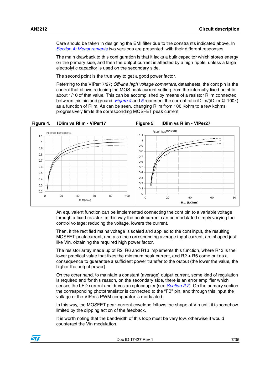
Referring to the VIPer17/27; Off-line high voltage converters, datasheets, the cont pin is the control that allows reducing the MOS peak current setting from the internally fixed point to about 1/10 of that value. This can be accomplished by means of a resistor Rlim connected between this pin and ground. Figure 4 and 5 represent the current ratio iDlim/(iDlim @ 100k) as a function of Rlim. As can be seen, changing Rlim from 100 Kohm to a few kohms progressively limits the corresponding MOSFET peak current.

Figure 4. IDlim vs Rlim - VIPer17

Figure 5. IDlim vs Rlim - VIPer27


An equivalent function can be implemented connecting the cont pin to a variable voltage through a fixed resistor; in this way the peak current can be modulated simply varying the control voltage: reducing the voltage, lowers the current.

Then, if the rectified mains voltage is scaled and applied to the cont input, the resulting MOSFET peak current, and also the corresponding average input current, are shaped just like Vin, obtaining the required high power factor.

The resistor array made up of R2, R6 and R13 implements this function, where R13 is the lower practical value that fixes the minimum peak current, and R2 + R6 come out as a consequence to guarantee a sufficient power transfer to the output (the lower the value, the higher the output power).

On the other hand, to maintain a constant (average) output current, some kind of regulation is required and for this reason, on the secondary side, there is an error amplifier which senses the LED current and drives an optocoupler (see Section 2.2). On the primary section the corresponding phototransistor is connected to the “FB” pin, and through this input the voltage of the VIPer's PWM comparator is modulated.

In this way, the MOSFET peak current envelope follows the shape of Vin until it is somehow limited by the clipping action of the feedback.

It is worth noting that the bandwidth of this loop must be very low, otherwise it would counteract the Vin modulation.

Doc ID 17427 Rev 1

7/35

ST AN3212 Application note

Circuit description

AN3212


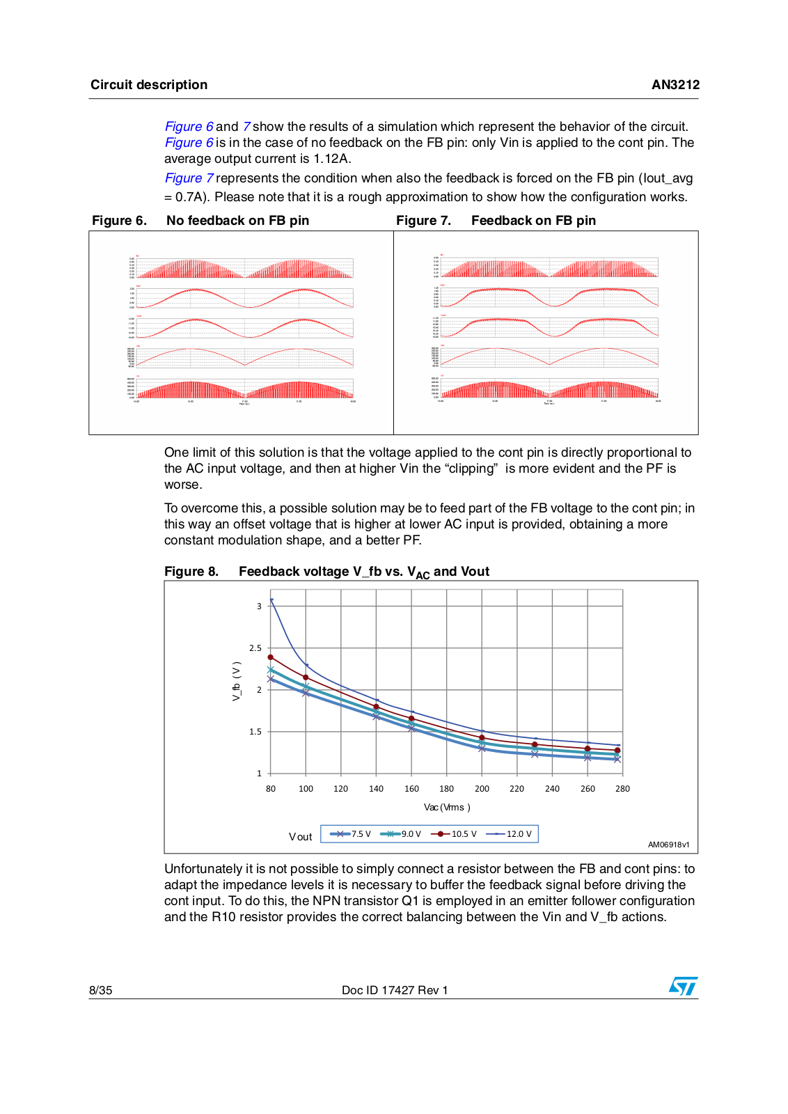
Figure 6 and 7 show the results of a simulation which represent the behavior of the circuit. Figure 6 is in the case of no feedback on the FB pin: only Vin is applied to the cont pin. The average output current is 1.12A.

Figure 7 represents the condition when also the feedback is forced on the FB pin (Iout_avg

= 0.7A). Please note that it is a rough approximation to show how the configuration works.

Figure 6. No feedback on FB pin

Figure 7. Feedback on FB pin


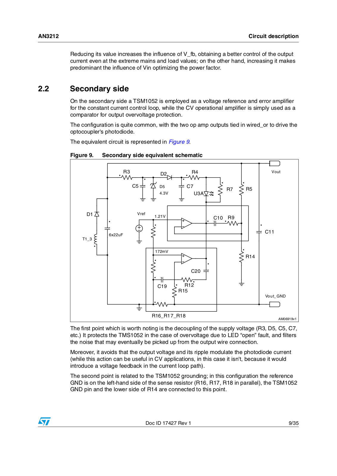
One limit of this solution is that the voltage applied to the cont pin is directly proportional to the AC input voltage, and then at higher Vin the “clipping” is more evident and the PF is worse.

To overcome this, a possible solution may be to feed part of the FB voltage to the cont pin; in this way an offset voltage that is higher at lower AC input is provided, obtaining a more constant modulation shape, and a better PF.

Figure 8. Feedback voltage V_fb vs. VAC and Vout

9BIE 9

ϯ

Ϯ͘ϱ

Ϯ

ϭ͘ϱ

ϭ

ϴϬ

ϭϬϬ


ϭϮϬ

ϭϰϬ

ϭϲϬ


ϭϴϬ

ϮϬϬ

ϮϮϬ

ϮϰϬ

ϮϲϬ

ϮϴϬ


9DF 9UPV


9 RXW


ϳ͘ϱs


ϵ͘Ϭs


ϭϬ͘ϱ s


ϭϮ͘Ϭ s


!-V

Unfortunately it is not possible to simply connect a resistor between the FB and cont pins: to adapt the impedance levels it is necessary to buffer the feedback signal before driving the cont input. To do this, the NPN transistor Q1 is employed in an emitter follower configuration and the R10 resistor provides the correct balancing between the Vin and V_fb actions.

8/35

Doc ID 17427 Rev 1

AN3212

Circuit description


Reducing its value increases the influence of V_fb, obtaining a better control of the output current even at the extreme mains and load values; on the other hand, increasing it makes predominant the influence of Vin optimizing the power factor.

2.2Secondary side

On the secondary side a TSM1052 is employed as a voltage reference and error amplifier for the constant current control loop, while the CV operational amplifier is simply used as a comparator for output overvoltage protection.

The configuration is quite common, with the two op amp outputs tied in wired_or to drive the optocoupler's photodiode.

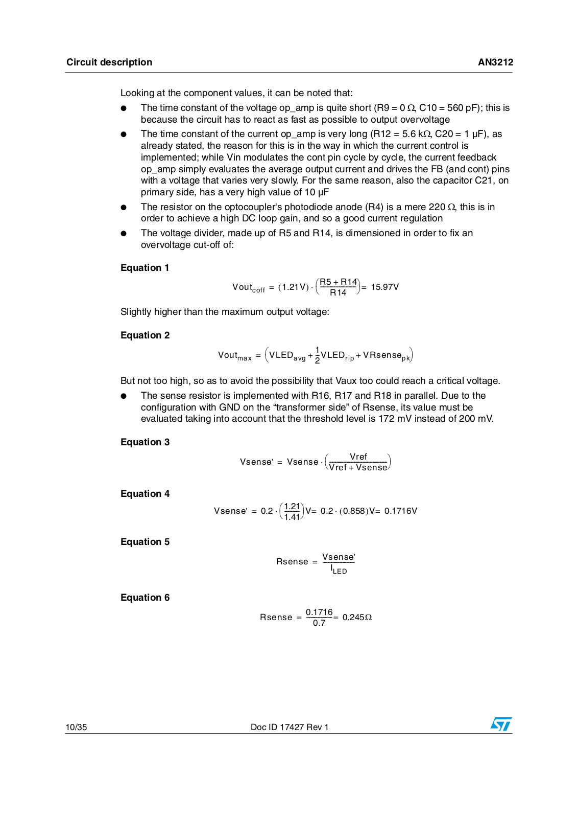
The equivalent circuit is represented in Figure 9.

Figure 9. Secondary side equivalent schematic


2

$

2


6OUT


#

$

#

2

2


6

5 !


$

6REF

6

#

2


X U&


#

4 ?


M6


2


#


#

2


2


6OUT?'.$


2 ?2 ?2


!-V


The first point which is worth noting is the decoupling of the supply voltage (R3, D5, C5, C7, etc.) It protects the TMS1052 in the case of overvoltage due to LED “open” fault, and filters the noise that may eventually be picked up from the output wire connection.

Moreover, it avoids that the output voltage and its ripple modulate the photodiode current (while this action can be useful in CV applications, in this case it isn't, because it would introduce a voltage feedback in the current loop path).

The second point is related to the TSM1052 grounding; in this configuration the reference GND is on the left-hand side of the sense resistor (R16, R17, R18 in parallel), the TSM1052 GND pin and the lower side of R14 are connected to this point.

Doc ID 17427 Rev 1

9/35

Circuit description

AN3212


Looking at the component values, it can be noted that:

The time constant of the voltage op_amp is quite short (R9 = 0 Ω, C10 = 560 pF); this is because the circuit has to react as fast as possible to output overvoltage

The time constant of the current op_amp is very long (R12 = 5.6 kΩ, C20 = 1 µF), as already stated, the reason for this is in the way in which the current control is implemented; while Vin modulates the cont pin cycle by cycle, the current feedback op_amp simply evaluates the average output current and drives the FB (and cont) pins with a voltage that varies very slowly. For the same reason, also the capacitor C21, on primary side, has a very high value of 10 µF

The resistor on the optocoupler's photodiode anode (R4) is a mere 220 Ω, this is in order to achieve a high DC loop gain, and so a good current regulation

The voltage divider, made up of R5 and R14, is dimensioned in order to fix an overvoltage cut-off of:

Equation 1

Voutcoff = (1.21V)

R5 + R14

=

15.97V

--------R14-----------------

Slightly higher than the maximum output voltage:

Equation 2

Vout


=

VLED


1


+ VRsense


max

avg

+ --VLED

rip


2


pk

But not too high, so as to avoid the possibility that Vaux too could reach a critical voltage.

The sense resistor is implemented with R16, R17 and R18 in parallel. Due to the configuration with GND on the “transformer side” of Rsense, its value must be evaluated taking into account that the threshold level is 172 mV instead of 200 mV.

Equation 3

Vsense'

= Vsense ---------------

Vref------------------------


Vref + Vsense

Equation 4

Vsense' = 0.2 1.21 V= 0.2 (0.858)V= 0.1716V

1.41-----------

Equation 5

Vsense'

Rsense = ----------------------

ILED

Equation 6

0.1716 Ω Rsense = -----------------= 0.245

0.7

10/35

Doc ID 17427 Rev 1

AN3212

Circuit description


2.3Circuit variants

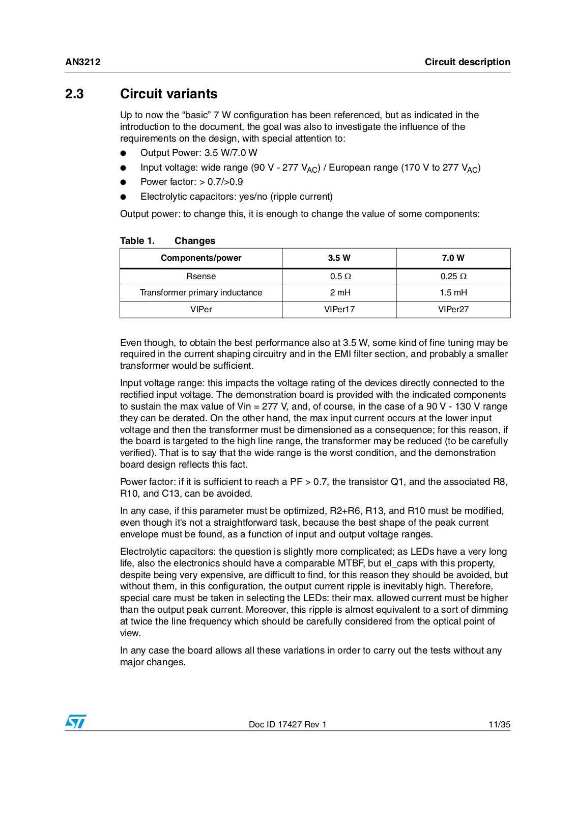
Up to now the “basic” 7 W configuration has been referenced, but as indicated in the introduction to the document, the goal was also to investigate the influence of the requirements on the design, with special attention to:

Output Power: 3.5 W/7.0 W

Input voltage: wide range (90 V - 277 VAC) / European range (170 V to 277 VAC)

Power factor: > 0.7/>0.9

Electrolytic capacitors: yes/no (ripple current)

Output power: to change this, it is enough to change the value of some components:

Table 1.

Changes


Components/power

3.5 W

7.0 W


Rsense

0.5 Ω

0.25 Ω


Transformer primary inductance

2 mH

1.5 mH


VIPer

VIPer17

VIPer27


Even though, to obtain the best performance also at 3.5 W, some kind of fine tuning may be required in the current shaping circuitry and in the EMI filter section, and probably a smaller transformer would be sufficient.

Input voltage range: this impacts the voltage rating of the devices directly connected to the rectified input voltage. The demonstration board is provided with the indicated components to sustain the max value of Vin = 277 V, and, of course, in the case of a 90 V - 130 V range they can be derated. On the other hand, the max input current occurs at the lower input voltage and then the transformer must be dimensioned as a consequence; for this reason, if the board is targeted to the high line range, the transformer may be reduced (to be carefully verified). That is to say that the wide range is the worst condition, and the demonstration board design reflects this fact.

Power factor: if it is sufficient to reach a PF > 0.7, the transistor Q1, and the associated R8, R10, and C13, can be avoided.

In any case, if this parameter must be optimized, R2+R6, R13, and R10 must be modified, even though it's not a straightforward task, because the best shape of the peak current envelope must be found, as a function of input and output voltage ranges.

Electrolytic capacitors: the question is slightly more complicated; as LEDs have a very long life, also the electronics should have a comparable MTBF, but el_caps with this property, despite being very expensive, are difficult to find, for this reason they should be avoided, but without them, in this configuration, the output current ripple is inevitably high. Therefore, special care must be taken in selecting the LEDs: their max. allowed current must be higher than the output peak current. Moreover, this ripple is almost equivalent to a sort of dimming at twice the line frequency which should be carefully considered from the optical point of view.

In any case the board allows all these variations in order to carry out the tests without any major changes.

Doc ID 17427 Rev 1

11/35

Loading...
+ 24 hidden pages