

Page 1

AN3202
Application note
How to configure the SPEAr600 general purpose timers (GPTs)
Introduction
This application note provides information about how to configure the general purpose
timers (GPTs) integrated in the SPEAr600 embedded MPU family.
General purpose timers (GPTs) play an important role in any system as they provide a
means of calculating time for controlling the execution of various operations. In case of an
operating system, they are used for the system tick generation, usually every 10 ms; in other
applications they can be used to get a finer granularity for controlling the timing of events.
The purpose of this application note is to explain how to read the free running timer counter
and configure the clock source of the various GPTs that are integrated in the SPEAr600
architecture.
May 2010 Doc ID 17399 Rev 1 1/11
www.st.com
Page 2

Contents AN3202
Contents
1 General purpose timers (GPTs) in SPEAr600 . . . . . . . . . . . . . . . . . . . . . 3
2 Reading a free-running timer counter . . . . . . . . . . . . . . . . . . . . . . . . . . . 5
3 Scenario with slow CNT_Clk and fast READ_Clk . . . . . . . . . . . . . . . . . 7
4 How to configure CNT_Clk and READ_Clk to be synchronous . . . . . . 8
5 Summary . . . . . . . . . . . . . . . . . . . . . . . . . . . . . . . . . . . . . . . . . . . . . . . . . . 9
6 Revision history . . . . . . . . . . . . . . . . . . . . . . . . . . . . . . . . . . . . . . . . . . . 10
2/11 Doc ID 17399 Rev 1
Page 3
AN3202 General purpose timers (GPTs) in SPEAr600
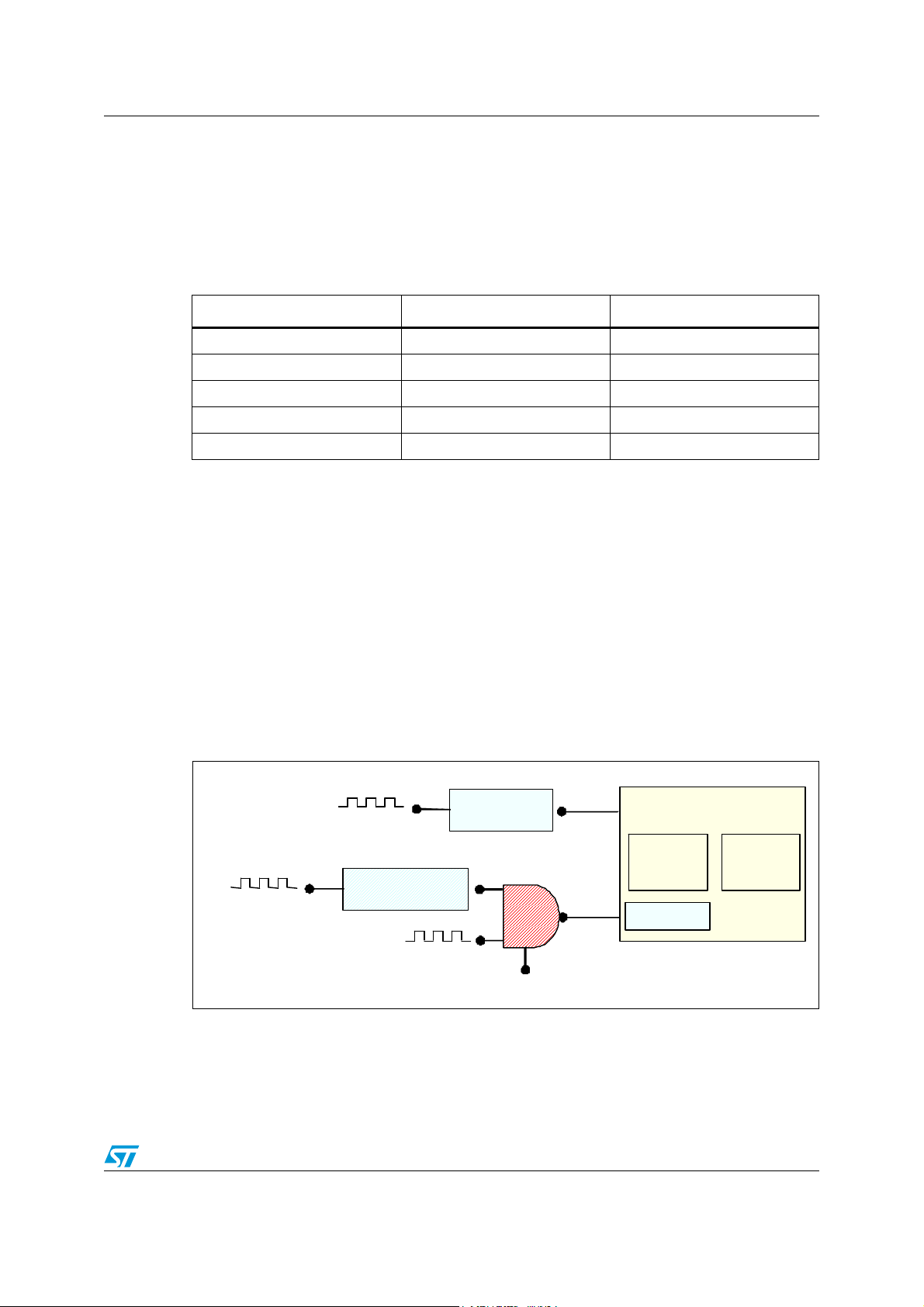
GPT Ch1 GPT Ch2
Read_CLK
(P CLK )
CNT_Clk
PLL3 (48MHz)
PRSCx_CLK_CFG
PLL1 (332MHz)/
OSCI (24MHz)
HCLK/PCLK
prescale r
PLL1 (332MHz)
1 General purpose timers (GPTs) in SPEAr600
In the SPEAr600 architecture, there are five different GPT blocks located in the various
subsystems. Each timer block consists of two independent channels, each one with a 16-bit
counter register.
Table 1. GPTs in SPEAr600
Subsystem Base address
GPT1 ARM1 0xF000_0000
GPT2 ARM2 0xF000_0000
GPT3 Basic 0xFC80_0000
GPT4 Application 1 0xD800_0000
GPT5 Application 2 0xD808_0000
Each timer has a READ_Clk, input which is the APB clock (PCLK), and a CNT_Clk, which
can be selected by the user from a list of clock sources.
● READ_Clk (PCLK): When SPEAr600 is in normal mode, it takes the input from PLL1
divided by a programmable prescaler, whose reset values impose the ratio 1:2:4 to the
core_clk, HCLK and PCLK clocks. When SPEAr600 is in slow mode, it takes directly
the input from the OSCI signal.
● CNT_Clk: The clock source can be selected as either a fixed 48 MHz or the PLL1 itself
divided by a programmable prescaler, which is defined in the PRSC1_CLK_CFG
register (0xFCA8_0044) for GPT1/GPT2/GPT3, PRSC2_CLK_CFG register
(0xFCA8_0048) for GPT4 and PRSC3_CLK_CFG register (0xFCA8_004C) for GPT5.
The CNT_Clk may then be further divided by a GPT internal 4-bit prescaler able to
divide up to 256 times (‘/256’).
Figure 1. GPT clock sources
The following table describes the clock selectors (Clock_Sel) for each GPT.
Doc ID 17399 Rev 1 3/11
MUX
Clock_Sel
int_prsc
Page 4

General purpose timers (GPTs) in SPEAr600 AN3202
Table 2. GPTx clock source selector
Register Address Value
GPT1 PRPH_CLK_CFG [08] 0xFCA8_0028 (bit8)
GPT2
GPT3
PRPH_CLK_CFG[09] 0xFCA8_0028 (bit9)
PRPH_CLK_CFG[10] 0xFCA8_0028 (bit10)
GPT4 PRPH_CLK_CFG[11] 0xFCA8_0028 (bit11)
GPT5 PRPH_CLK_CFG[12] 0xFCA8_0028 (bit12)
0: PLL3 48 MHz
1: PLL1 (
PRSC1_CLK_CFG)
0: PLL3 48 MHz
1: PLL1 (
PRSC1_CLK_CFG)
0: PLL3 48 MHz
1: PLL1 (
PRSC1_CLK_CFG)
0: PLL3 48 MHz
1: PLL1 (
PRSC2_CLK_CFG)
0: PLL3 48 MHz
1: PLL1 (
PRSC3_CLK_CFG)
The SPEAr600 GPTs always generate precise alarm interrupts, for example in the case of a
system tick for a RTOS. Nevertheless, as you can see in
Section 2: Reading a free-running
timer counter, GPTs can return unpredictable read values when they are running and the
input clock is asynchronous (or not in phase).
4/11 Doc ID 17399 Rev 1
Page 5

AN3202 Reading a free-running timer counter
CNT_Clk
0 0 1 0 1
READ_Clk
CNT_Clk
READ_Clk
Bit_N
t0 t1 t2
t0: On CNT_Cl k rising edg e, Bit_N
start a 0->1 tran sitioni ng
t1:
On RE AD_C lk rising edge, Bit_N i s
sam pled in an uns tab le state
t2:
Bit_N reaches a stable state
2 Reading a free-running timer counter
When the GPT interrupt is enabled, the interrupts generated at each timer wrap-around
condition are always triggered at the right frequency, however reading the timer counter
when the timer itself is active and free-running may present some difficulties which are
described below.
In a simplified scenario, a hardware timer block can be seen just as a simple counter
register with two input clocks:CNT_Clk for incrementing/decrementing the counter and
READ_Clk for synchronizing the READ accesses of the bus the timer is connected to.
Figure 2. Simplified timer
…
The two clocks can be either synchronous, coming from the same source PCLK, or
completely asynchronous, for example coming from two different sources.
When the two clocks involved in the scenario are asynchronous, then the value retrieved by
the CPU in a read counter operation is unpredictable, and might be completely different from
the real value in the register.
The situation is due to the fact that the READ_Clk is sampling the counter bits while they are
in a transitioning, unstable phase.
Figure 3. Sampling a counter bit in an unstable state
The above scenario may take place during any kind of transition (0->1 or 1->0) and for any
bit in the register.
If one of the bits impacted has a large weight (significant position) in the counter, then the
difference between the value returned in the read transaction and the real value of the
counter can be very large.
Doc ID 17399 Rev 1 5/11
Page 6

Reading a free-running timer counter AN3202
Let’s take as an example a counting down 16-bit counter transitioning from the value
1000_0000_0000_0000 (0x8000) to 0111_1111_1111_1111 (0x7FFF). Since the transition
time of the 16 bits can be slightly different between each other, then the 16-bit counter value
could be read by the CPU randomly as 0x0000 or 0xFFFF leading to a big difference from
its real value.
A similar scenario may also occur in case the two clocks are synchronous, but not in phase.
In this case, in fact, the READ_Clk may sample the bit during its unstable state period.
So, the two clocks must be synchronous and in phase.
6/11 Doc ID 17399 Rev 1
Page 7

AN3202 Scenario with slow CNT_Clk and fast READ_Clk
READ_Clk
(PC
CNT_Clk
(48M Hz/32 == 1.5 M Hz )
Bit_N
t0
t2
t0: Bit_N is sampled in an unstable
state
t1 & t2:
Bit_ N is sam pled in a
stab le state. S am ples are assu med
to happen ev ery 3 RE AD_Clk cycles.
3 Scenario with slow CNT_Clk and fast READ_Clk
In certain cases, for example when the timer is used by an operating system to generate the
system tick, the CNT_Clk (after prescaling) is usually much slower than READ_Clk. For
example, let’s suppose you need to generate a tick every 10 ms; the GPT with a clock
source of 48
to 15000.
This results in a great number (around 60) READ_Clk ‘sampling cycles’ for every single
CNT_Clk cycle. Or, in other words, CNT_Clk is about 60 times slower than READ_Clk.
Figure 4. CNT_Clk at low frequency
MHz might be programmed using a ‘/32’ internal prescaler and a counter equal
LK = = 83MHz)
Let’s see what happens if the CPU does three consecutive read operations instead of a
single one. Since the bit instability lasts much less than the CNT_Clk time period, we can
say that, out of 3 READ_Clk edges, only one will ever fall into the bit instability window. The
other two are stable.
Moreover, since CNT_Clk is about 60 times slower than READ_Clk, the two stable read
operations return counter values that differ by 1 in the worst case, which is when there is a
CNT_Clk rising edge between the first and third read operations. Of course, interrupts
should be disabled during the reads.
So, reading three times the counter and discharging the unstable value (if any) is a valid
workaround that can be used for all GPTs of SPEAr600 in similar scenarios. In particular,
this method might be used for GPT1, GPT2 and GPT3.
In general, this workaround is valid when the minimum period of CNT_Clk is greater than 3
times the read_cycle_time. The read_cycle_time depends
on the CPU frequency, and also
on the way the reads are implemented, so they should be carefully evaluated.
Doc ID 17399 Rev 1 7/11
Page 8

How to configure CNT_Clk and READ_Clk to be synchronous AN3202
4 How to configure CNT_Clk and READ_Clk to be
synchronous
This method, which is very simple to implement, is nevertheless guaranteed to work for
GPT4 and GPT5 only.
The most common configuration is when SPEAr600 is in normal mode with system clocks
fed by PLL1. In case the system is set in this mode, you can just select PLL1 as CNT_Clk to
guarantee the synchronicity between CNT_Clk and READ_Clk.
To set the input clock source of GPTx to PLL1 you need to use PRPH_CLK_CFG register
(0xFCA8_0028). There are five different bits, one for each GPT block.
● For GPT4: PRPH_CLK_CFG [11] = 1
● For GPT5: PRPH_CLK_CFG [12] = 1
In case SPEAr600 enters the slow mode, for example to save power after detecting a period
of inactivity, the HCLK/PCLK system clocks are directly fed from the OSCI at 30
mode READ_Clk (OSCI) and CNT_Clk (PLL1) become asynchronous again.
MHz. In this
8/11 Doc ID 17399 Rev 1
Page 9

AN3202 Summary
5 Summary
A general purpose timer can be seen as a simple counter with two clocks in input:
READ_Clk (for the slave interface) and CNT_Clk (for incrementing/decrementing the
counter).
The CNT_Clk for the GPT in SPEAr600 can be selected between a fixed 48 MHz source
and PLL1, which is also the source clock for the rest of the system. The READ_Clk is
derived from PLL1 in normal mode (PCLK) and from the 30
Having a fixed clock source different from the system clock has the advantage of eliminating
the need for reconfiguring the GPT registers if the system clock frequency is slowed down.
However, it introduces the possibility of obtaining an unpredictable result when reading the
timer value, due to the non-synchronous operation of the two clocks.
In case CNT_Clk is much slower than READ_Clk, three consecutives read of the counter (3reads workaround) guarantees to have at least two stable values with a maximum difference
of 1.
The following table summarizes the suggested solutions for this issue:
Table 3. Summary of the solutions
MHz OSCI in slow mode.
Subsystem Solution in normal mode Solution in slow mode
GPT1 ARM1 3-reads workaround 3-reads workaround
GPT2 ARM2 3-reads workaround 3-reads workaround
GPT3 Basic 3-reads workaround 3-reads workaround
GPT4 Application1
GPT5 Application2
Keep READ_Clk and
CNT_Clk synchronous
Keep READ_Clk and
CNT_Clk synchronous
3-reads workaround
3-reads workaround
Doc ID 17399 Rev 1 9/11
Page 10

Revision history AN3202
6 Revision history
Table 4. Document revision history
Date Revision Changes
03-May-2010 1 Initial release.
10/11 Doc ID 17399 Rev 1
Page 11

AN3202
Please Read Carefully:
Information in this document is provided solely in connection with ST products. STMicroelectronics NV and its subsidiaries (“ST”) reserve the
right to make changes, corrections, modifications or improvements, to this document, and the products and services described herein at any
time, without notice.
All ST products are sold pursuant to ST’s terms and conditions of sale.
Purchasers are solely responsible for the choice, selection and use of the ST products and services described herein, and ST assumes no
liability whatsoever relating to the choice, selection or use of the ST products and services described herein.
No license, express or implied, by estoppel or otherwise, to any intellectual property rights is granted under this document. If any part of this
document refers to any third party products or services it shall not be deemed a license grant by ST for the use of such third party products
or services, or any intellectual property contained therein or considered as a warranty covering the use in any manner whatsoever of such
third party products or services or any intellectual property contained therein.
UNLESS OTHERWISE SET FORTH IN ST’S TERMS AND CONDITIONS OF SALE ST DISCLAIMS ANY EXPRESS OR IMPLIED
WARRANTY WITH RESPECT TO THE USE AND/OR SALE OF ST PRODUCTS INCLUDING WITHOUT LIMITATION IMPLIED
WARRANTIES OF MERCHANTABILITY, FITNESS FOR A PARTICULAR PURPOSE (AND THEIR EQUIVALENTS UNDER THE LAWS
OF ANY JURISDICTION), OR INFRINGEMENT OF ANY PATENT, COPYRIGHT OR OTHER INTELLECTUAL PROPERTY RIGHT.
UNLESS EXPRESSLY APPROVED IN WRITING BY AN AUTHORIZED ST REPRESENTATIVE, ST PRODUCTS ARE NOT
RECOMMENDED, AUTHORIZED OR WARRANTED FOR USE IN MILITARY, AIR CRAFT, SPACE, LIFE SAVING, OR LIFE SUSTAINING
APPLICATIONS, NOR IN PRODUCTS OR SYSTEMS WHERE FAILURE OR MALFUNCTION MAY RESULT IN PERSONAL INJURY,
DEATH, OR SEVERE PROPERTY OR ENVIRONMENTAL DAMAGE. ST PRODUCTS WHICH ARE NOT SPECIFIED AS "AUTOMOTIVE
GRADE" MAY ONLY BE USED IN AUTOMOTIVE APPLICATIONS AT USER’S OWN RISK.
Resale of ST products with provisions different from the statements and/or technical features set forth in this document shall immediately void
any warranty granted by ST for the ST product or service described herein and shall not create or extend in any manner whatsoever, any
liability of ST.
ST and the ST logo are trademarks or registered trademarks of ST in various countries.
Information in this document supersedes and replaces all information previously supplied.
The ST logo is a registered trademark of STMicroelectronics. All other names are the property of their respective owners.
© 2010 STMicroelectronics - All rights reserved
STMicroelectronics group of companies
Australia - Belgium - Brazil - Canada - China - Czech Republic - Finland - France - Germany - Hong Kong - India - Israel - Italy - Japan -
Malaysia - Malta - Morocco - Philippines - Singapore - Spain - Sweden - Switzerland - United Kingdom - United States of America
www.st.com
Doc ID 17399 Rev 1 11/11
 Loading...