ST AN3174 Application note

AN3174

Application note

Implementing receivers for infrared remote control protocols using STM32F10xxx microcontrollers

Introduction

Infrared radiation is the region of the electromagnetic spectrum which lies between microwaves and visible light.

Infrared radiation has two ranges. Near infrared light is closest in wavelength to visible light and far infrared is closer to the microwave region of the electromagnetic spectrum.

The shorter waves are the ones used by remote controls. Information is transmitted and received using electromagnetic energy, without using wires.

Infrared technology offers important advantages as a form of wireless communication. Nowadays, almost all audio and video equipment can be controlled using an infrared remote control. At the receiving end, a receiver detects the light pulses, which are processed to retrieve/decode the information they contain.

There are many popular infrared protocols used to transmit data via infrared light, such as

RC5, SIRC, ...

The purpose of this application note is to provide a generic solution for implementing an IR receiver in software using a STM32F10xxx microcontroller. Example of software implementation is provided for RC5 and SIRC protocols, other protocols are supported and available upon request (for further information contact your local STMicroelectronics sales office).

February 2012

Doc ID 17249 Rev 2

1/34

www.st.com

Contents

AN3174


Contents

1

Hardware considerations . . . . . . . . . . . . . . . . . . . . . . . . . . . . . . . . . . . . .

3

2

Generic solution . . . . . . . . . . . . . . . . . . . . . . . . . . . . . . . . . . . . . . . . . . . .

4

3

RC5 protocol solutions . . . . . . . . . . . . . . . . . . . . . . . . . . . . . . . . . . . . . . .

5


3.1 Protocol basics . . . . . . . . . . . . . . . . . . . . . . . . . . . . . . . . . . . . . . . . . . . . . .

5

3.2Software implementation using a single GPIO

with a generic timer . . . . . . . . . . . . . . . . . . . . . . . . . . . . . . . . . . . . . . . . . . 7

3.2.1 RC5 frame reading mechanism . . . . . . . . . . . . . . . . . . . . . . . . . . . . . . . . 7

3.3Software implementation using a GP-Timer configured

in PWM input mode . . . . . . . . . . . . . . . . . . . . . . . . . . . . . . . . . . . . . . . . . 10

3.3.1 RC5 Frame decoding mechanism . . . . . . . . . . . . . . . . . . . . . . . . . . . . . 10 3.3.2 RC5 library . . . . . . . . . . . . . . . . . . . . . . . . . . . . . . . . . . . . . . . . . . . . . . . 13 3.3.3 How to use the RC5 decoder driver . . . . . . . . . . . . . . . . . . . . . . . . . . . . 14


3.4

Comparison of RC5 solutions . . . . . . . . . . . . . . . . . . . . . . . . . . . . . . . . .

15

4

SIRC infrared control solution . . . . . . . . . . . . . . . . . . . . . . . . . . . . . . . .

17


4.1

Protocol basics . . . . . . . . . . . . . . . . . . . . . . . . . . . . . . . . . . . . . . . . . . . . .

17


4.2

Software implementation . . . . . . . . . . . . . . . . . . . . . . . . . . . . . . . . . . . . .

19


4.3

SIRC library . . . . . . . . . . . . . . . . . . . . . . . . . . . . . . . . . . . . . . . . . . . . . . .

21


4.4

How to use the SIRC decoder driver . . . . . . . . . . . . . . . . . . . . . . . . . . . .

22

5

Interface layer . . . . . . . . . . . . . . . . . . . . . . . . . . . . . . . . . . . . . . . . . . . . .

24

6

How to use the IR driver . . . . . . . . . . . . . . . . . . . . . . . . . . . . . . . . . . . . .

26


6.1

Demonstration programs . . . . . . . . . . . . . . . . . . . . . . . . . . . . . . . . . . . . .

26


6.1.1

Demo using GP-Timer configured in PWM mode . . . . . . . . . . . . . . . . .

26


6.1.2

RC5 demo using a single GPIO with generic timer . . . . . . . . . . . . . . . .

26

7

How to customize the IR drivers . . . . . . . . . . . . . . . . . . . . . . . . . . . . . .

28

8

Conclusion .

. . . . . . . . . . . . . . . . . . . . . . . . . . . . . . . . . . . . . . . . . . . . . . .

31

9

Revision history . . . . . . . . . . . . . . . . . . . . . . . . . . . . . . . . . . . . . . . . . . .

32

2/34

Doc ID 17249 Rev 2

AN3174

Hardware considerations


1

Hardware considerations


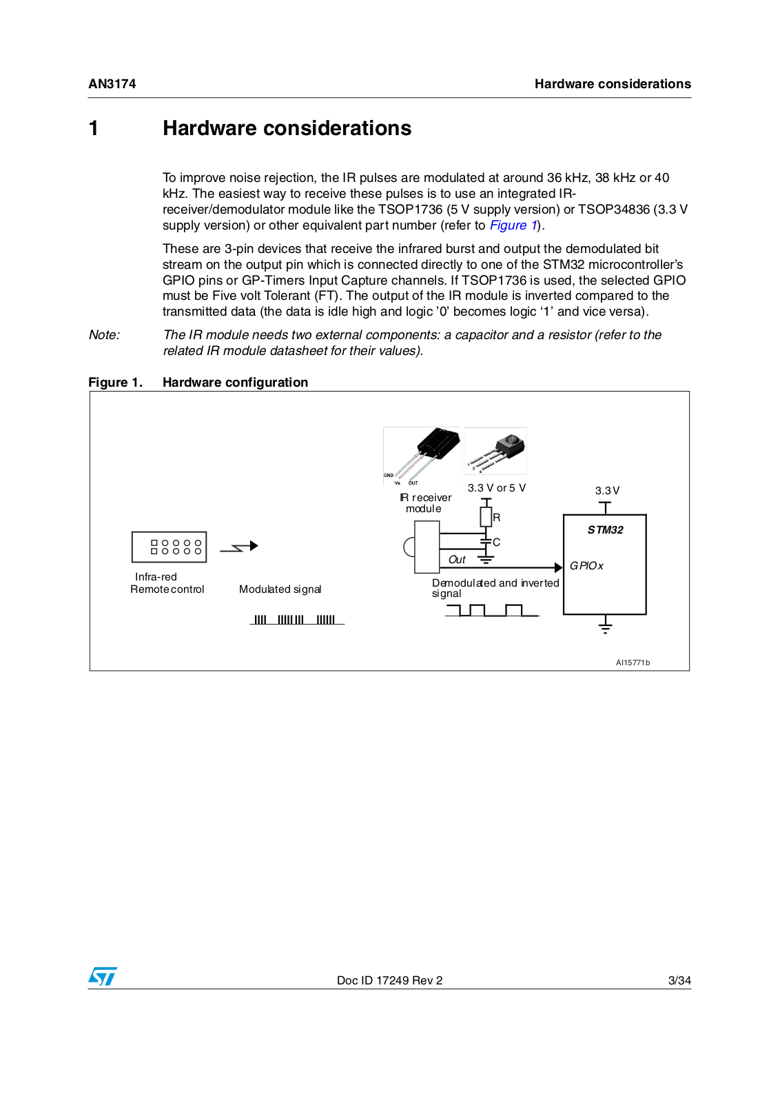
To improve noise rejection, the IR pulses are modulated at around 36 kHz, 38 kHz or 40


kHz. The easiest way to receive these pulses is to use an integrated IR-


receiver/demodulator module like the TSOP1736 (5 V supply version) or TSOP34836 (3.3 V


supply version) or other equivalent part number (refer to Figure 1).


These are 3-pin devices that receive the infrared burst and output the demodulated bit


stream on the output pin which is connected directly to one of the STM32 microcontroller’s


GPIO pins or GP-Timers Input Capture channels. If TSOP1736 is used, the selected GPIO


must be Five volt Tolerant (FT). The output of the IR module is inverted compared to the


transmitted data (the data is idle high and logic ’0’ becomes logic ‘1’ and vice versa).

Note:

The IR module needs two external components: a capacitor and a resistor (refer to the


related IR module datasheet for their values).

Figure 1.

Hardware configuration


3.3 V or 5 V

3.3 V


IR receiver


module


R

STM32


C


Out

GPIOx

Infra-red


Demodulated and inverted


Remote control

Modulated signal


signal


AI15771b

Doc ID 17249 Rev 2

3/34

Generic solution

AN3174


2 Generic solution

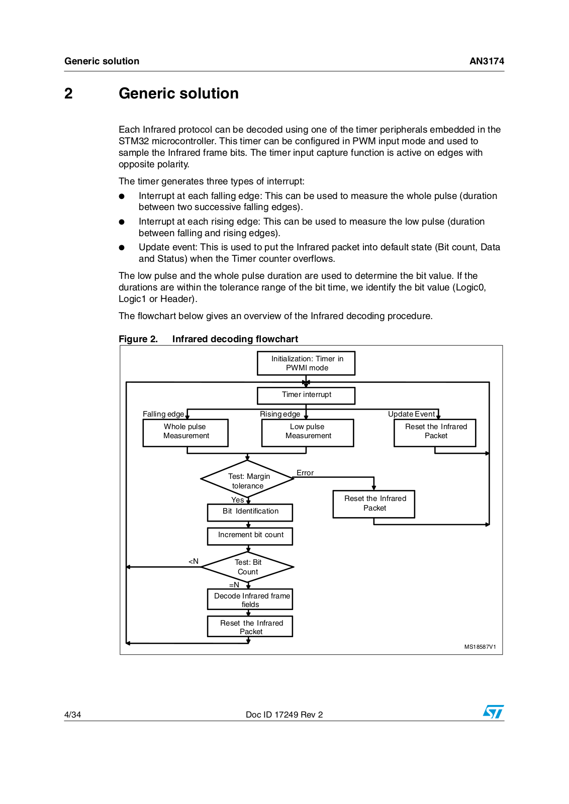
Each Infrared protocol can be decoded using one of the timer peripherals embedded in the STM32 microcontroller. This timer can be configured in PWM input mode and used to sample the Infrared frame bits. The timer input capture function is active on edges with opposite polarity.

The timer generates three types of interrupt:

Interrupt at each falling edge: This can be used to measure the whole pulse (duration between two successive falling edges).

Interrupt at each rising edge: This can be used to measure the low pulse (duration between falling and rising edges).

Update event: This is used to put the Infrared packet into default state (Bit count, Data and Status) when the Timer counter overflows.

The low pulse and the whole pulse duration are used to determine the bit value. If the durations are within the tolerance range of the bit time, we identify the bit value (Logic0, Logic1 or Header).

The flowchart below gives an overview of the Infrared decoding procedure.

Figure 2. Infrared decoding flowchart


)NITIALIZATION 4IMERRIN


07-))MODE


4IMERRINTERRUPT


&ALLING EDGE

2ISINGEDGE

5PDATE %VENT

7HOLEEPULSEE


,OWWPULSEE

2ESET THE )NFRARED

-EASUREMENT


-EASUREMENT

0ACKET

4EST -ARGIN

%RROR


TOLERANCE


9ES


2ESET THE )NFRARED

"IT

)DENTIFICATION


0ACKET


)NCREMENT BIT COUNT


.

4EST "IT


#OUNT


.


$ECODE )NFRAREDDFRAME


FIELDS


2ESET THE )NFRARED


0ACKET


-3 6

4/34

Doc ID 17249 Rev 2

AN3174

RC5 protocol solutions


3 RC5 protocol solutions

3.1Protocol basics

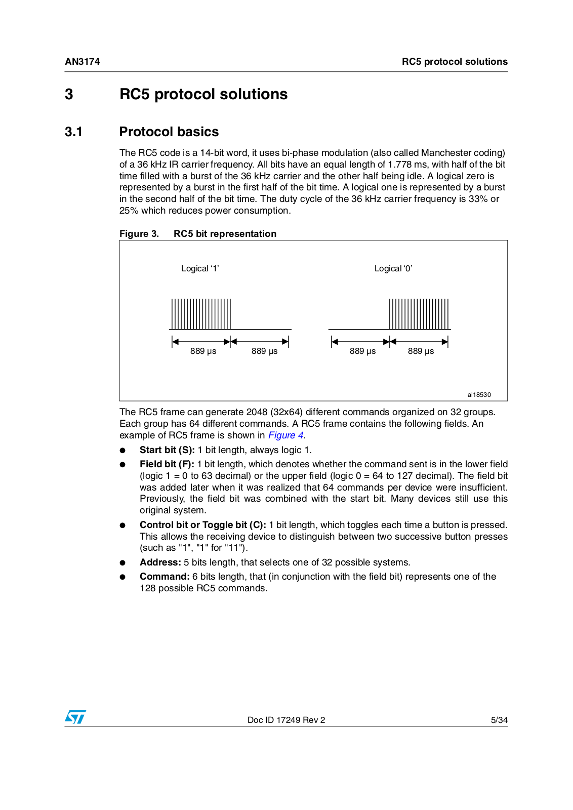
The RC5 code is a 14-bit word, it uses bi-phase modulation (also called Manchester coding) of a 36 kHz IR carrier frequency. All bits have an equal length of 1.778 ms, with half of the bit time filled with a burst of the 36 kHz carrier and the other half being idle. A logical zero is represented by a burst in the first half of the bit time. A logical one is represented by a burst in the second half of the bit time. The duty cycle of the 36 kHz carrier frequency is 33% or 25% which reduces power consumption.

Figure 3. RC5 bit representation

,OGICALI@

,OGICALI@


S


S


S


S


AI

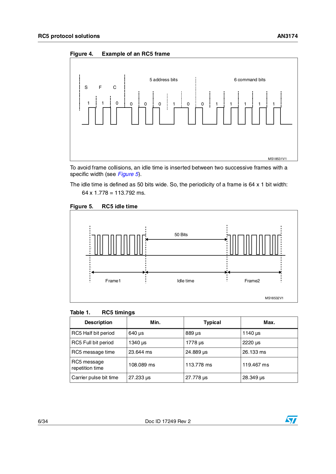
The RC5 frame can generate 2048 (32x64) different commands organized on 32 groups. Each group has 64 different commands. A RC5 frame contains the following fields. An example of RC5 frame is shown in Figure 4.

Start bit (S): 1 bit length, always logic 1.

Field bit (F): 1 bit length, which denotes whether the command sent is in the lower field (logic 1 = 0 to 63 decimal) or the upper field (logic 0 = 64 to 127 decimal). The field bit was added later when it was realized that 64 commands per device were insufficient. Previously, the field bit was combined with the start bit. Many devices still use this original system.

Control bit or Toggle bit (C): 1 bit length, which toggles each time a button is pressed. This allows the receiving device to distinguish between two successive button presses (such as "1", "1" for "11").

Address: 5 bits length, that selects one of 32 possible systems.

Command: 6 bits length, that (in conjunction with the field bit) represents one of the 128 possible RC5 commands.

Doc ID 17249 Rev 2

5/34

RC5 protocol solutions

AN3174


Figure 4. Example of an RC5 frame


ADDRESS BITSS


COMMANDDBITS


3

&

#


-3 6

To avoid frame collisions, an idle time is inserted between two successive frames with a specific width (see Figure 5).

The idle time is defined as 50 bits wide. So, the periodicity of a frame is 64 x 1 bit width:

64 x 1.778 = 113.792 ms.

Figure 5. RC5 idle time


"ITS


&RAME

)DLE TIME

&RAME


-3 6

Table 1.

RC5 timings


Description

Min.

Typical

Max.


RC5 Half bit period

640 µs

889 µs

1140 µs


RC5 Full bit period

1340 µs

1778 µs

2220 µs


RC5 message time

23.644 ms

24.889 µs

26.133 ms


RC5 message

108.089 ms

113.778 ms

119.467 ms

repetition time


Carrier pulse bit time

27.233 µs

27.778 µs

28.349 µs


6/34

Doc ID 17249 Rev 2

AN3174

RC5 protocol solutions


3.2Software implementation using a single GPIO with a generic timer

3.2.1RC5 frame reading mechanism

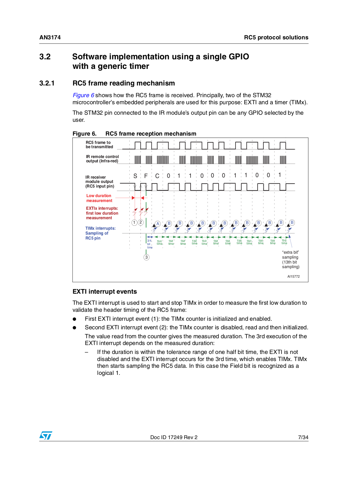
Figure 6 shows how the RC5 frame is received. Principally, two of the STM32 microcontroller’s embedded peripherals are used for this purpose: EXTI and a timer (TIMx).

The STM32 pin connected to the IR module’s output pin can be any GPIO selected by the user.

Figure 6. RC5 frame reception mechanism

RC5 frame to be transmitted

IR remote control output (Infra-red)

IR receiver module output (RC5 input pin)

Low duration measurement

EXTIx interrupts: first low duration measurement

TIMx interrupts: Sampling of RC5 pin

S F C 0 1 1 0 0 0 1 1 0 0 1

1 2


A

B

B

B

B

B

B

B

B

B

B

B

B


3/4

1bit


1bit


1bit


1bit

1bit


1bit


1bit


1bit

1bit


1bit


1bit


1bit


bit

time


time


time


time

time


time


time


time

time


time


time


time


time

“extra bit” 3 sampling

(13th bit sampling)

AI15772

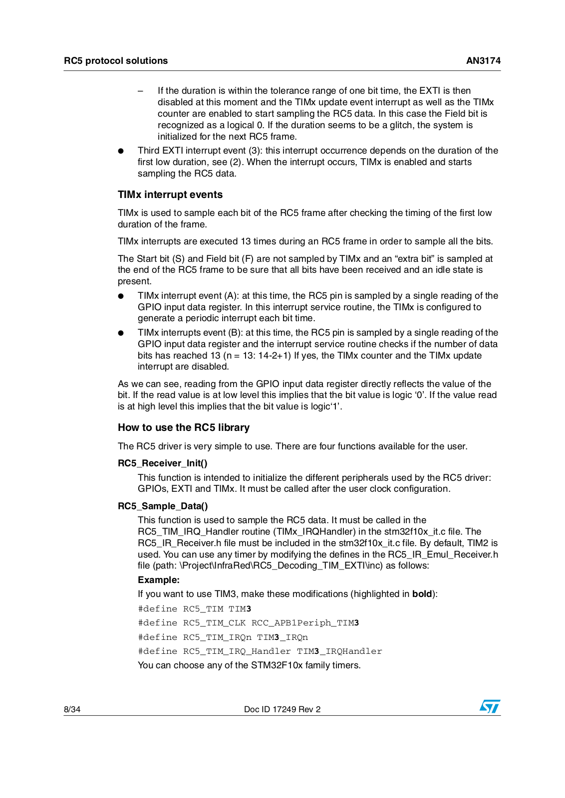
EXTI interrupt events

The EXTI interrupt is used to start and stop TIMx in order to measure the first low duration to validate the header timing of the RC5 frame:

First EXTI interrupt event (1): the TIMx counter is initialized and enabled.

Second EXTI interrupt event (2): the TIMx counter is disabled, read and then initialized.

The value read from the counter gives the measured duration. The 3rd execution of the EXTI interrupt depends on the measured duration:

If the duration is within the tolerance range of one half bit time, the EXTI is not disabled and the EXTI interrupt occurs for the 3rd time, which enables TIMx. TIMx then starts sampling the RC5 data. In this case the Field bit is recognized as a logical 1.

Doc ID 17249 Rev 2

7/34

RC5 protocol solutions

AN3174


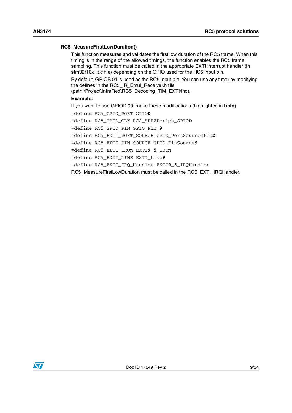
If the duration is within the tolerance range of one bit time, the EXTI is then disabled at this moment and the TIMx update event interrupt as well as the TIMx counter are enabled to start sampling the RC5 data. In this case the Field bit is recognized as a logical 0. If the duration seems to be a glitch, the system is initialized for the next RC5 frame.

Third EXTI interrupt event (3): this interrupt occurrence depends on the duration of the first low duration, see (2). When the interrupt occurs, TIMx is enabled and starts sampling the RC5 data.

TIMx interrupt events

TIMx is used to sample each bit of the RC5 frame after checking the timing of the first low duration of the frame.

TIMx interrupts are executed 13 times during an RC5 frame in order to sample all the bits.

The Start bit (S) and Field bit (F) are not sampled by TIMx and an “extra bit” is sampled at the end of the RC5 frame to be sure that all bits have been received and an idle state is present.

TIMx interrupt event (A): at this time, the RC5 pin is sampled by a single reading of the GPIO input data register. In this interrupt service routine, the TIMx is configured to generate a periodic interrupt each bit time.

TIMx interrupts event (B): at this time, the RC5 pin is sampled by a single reading of the GPIO input data register and the interrupt service routine checks if the number of data bits has reached 13 (n = 13: 14-2+1) If yes, the TIMx counter and the TIMx update interrupt are disabled.

As we can see, reading from the GPIO input data register directly reflects the value of the bit. If the read value is at low level this implies that the bit value is logic ‘0’. If the value read is at high level this implies that the bit value is logic‘1’.

How to use the RC5 library

The RC5 driver is very simple to use. There are four functions available for the user.

RC5_Receiver_Init()

This function is intended to initialize the different peripherals used by the RC5 driver: GPIOs, EXTI and TIMx. It must be called after the user clock configuration.

RC5_Sample_Data()

This function is used to sample the RC5 data. It must be called in the RC5_TIM_IRQ_Handler routine (TIMx_IRQHandler) in the stm32f10x_it.c file. The RC5_IR_Receiver.h file must be included in the stm32f10x_it.c file. By default, TIM2 is used. You can use any timer by modifying the defines in the RC5_IR_Emul_Receiver.h file (path: \Project\InfraRed\RC5_Decoding_TIM_EXTI\inc) as follows:

Example:

If you want to use TIM3, make these modifications (highlighted in bold):

#define RC5_TIM TIM3

#define RC5_TIM_CLK RCC_APB1Periph_TIM3

#define RC5_TIM_IRQn TIM3_IRQn

#define RC5_TIM_IRQ_Handler TIM3_IRQHandler

You can choose any of the STM32F10x family timers.

8/34

Doc ID 17249 Rev 2

AN3174

RC5 protocol solutions


RC5_MeasureFirstLowDuration()

This function measures and validates the first low duration of the RC5 frame. When this timing is in the range of the allowed timings, the function enables the RC5 frame sampling. This function must be called in the appropriate EXTI interrupt handler (in stm32f10x_it.c file) depending on the GPIO used for the RC5 input pin.

By default, GPIOB.01 is used as the RC5 input pin. You can use any timer by modifying the defines in the RC5_IR_Emul_Receiver.h file (path:\Project\InfraRed\RC5_Decoding_TIM_EXTI\inc).

Example:

If you want to use GPIOD.09, make these modifications (highlighted in bold):

#define RC5_GPIO_PORT GPIOD

#define RC5_GPIO_CLK RCC_APB2Periph_GPIOD

#define RC5_GPIO_PIN GPIO_Pin_9

#define RC5_EXTI_PORT_SOURCE GPIO_PortSourceGPIOD

#define RC5_EXTI_PIN_SOURCE GPIO_PinSource9

#define RC5_EXTI_IRQn EXTI9_5_IRQn #define RC5_EXTI_LINE EXTI_Line9

#define RC5_EXTI_IRQ_Handler EXTI9_5_IRQHandler

RC5_MeasureFirstLowDuration must be called in the RC5_EXTI_IRQHandler.

Doc ID 17249 Rev 2

9/34

RC5 protocol solutions

AN3174


RC5_Decode()

This function is intended to be called in the user application. It decodes the RC5 received messages. It returns a structure that contains the different values of the RC5 frame.

typedef struct

{

__IO uint8_t ToggleBit; /* Toggle bit field */ __IO uint8_t Address; /* Address field */

__IO uint8_t Command; /* Command field */ } RC5Frame_TypeDef ;

RC5_decode() must be called when the IR_FrameReceived flag is equal to YES.

Example:

/* System Clocks Configuration */ RCC_Configuration();

/* Initialize RC5 reception */ RC5_Receiver_Init();

while (1)

{

/* If RC5 frame has been received, then decode it */ if (IR_FrameReceived == YES)

{

/* Get the RC5 frame */ RC5_Frame = RC5_Decode();

}

}

3.3Software implementation using a GP-Timer configured in PWM input mode

3.3.1RC5 Frame decoding mechanism

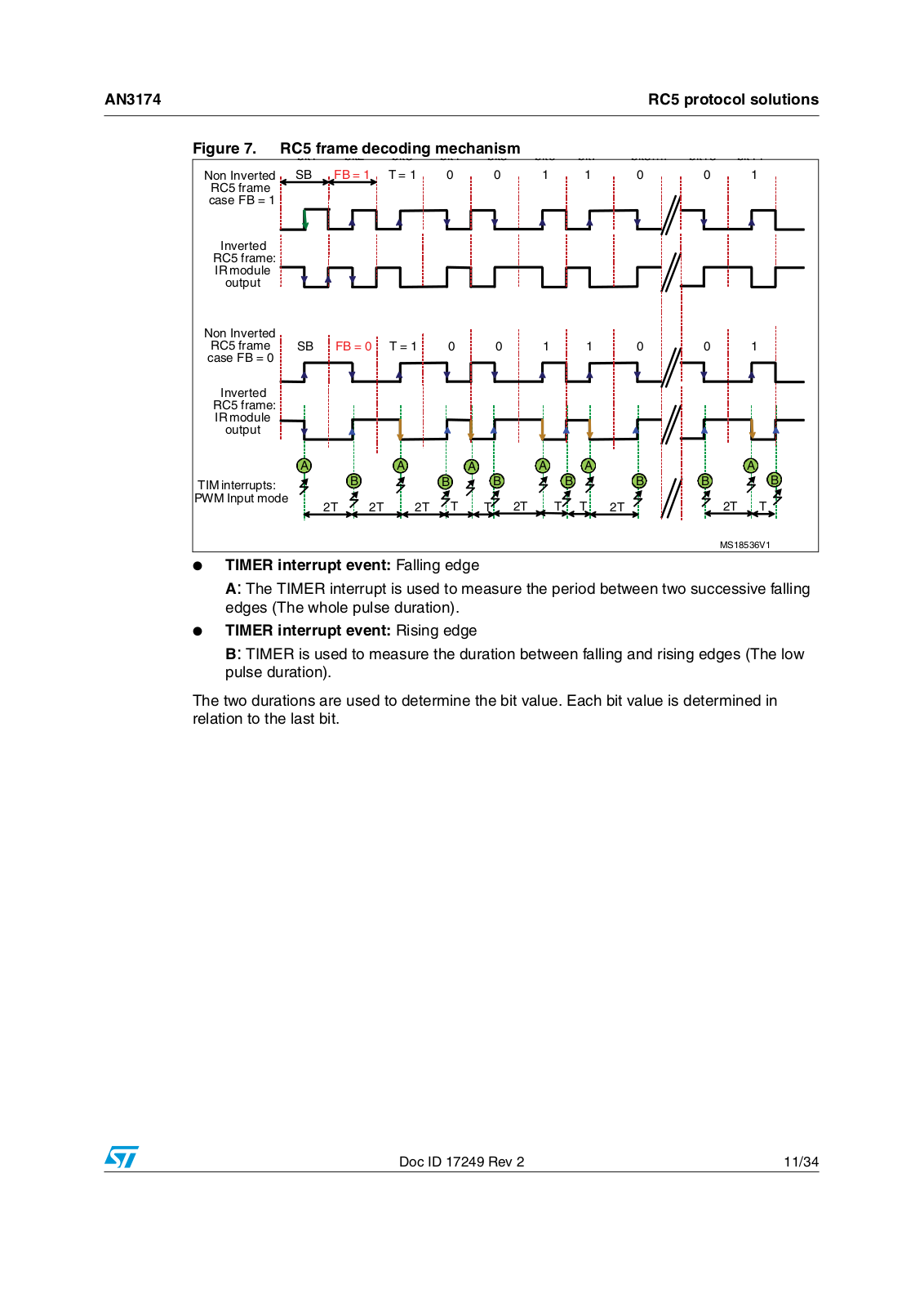
Figure 7 shows how the RC5 frame is received. One of the STM32 microcontroller’s embedded peripherals is used for this purpose: TIMER configured in mode PWM input.

This input can capture the current timer value both at falling and rising edges as well as generate an interrupt on both edges. This feature makes it easy to measure the RC5 pulse high and low times.

10/34

Doc ID 17249 Rev 2

ST AN3174 Application note

AN3174

RC5 protocol solutions


Figure 7. RC5 frame decoding mechanism

.ON )NVERTED 3" &" 44


2# FRAME CASE &"

)NVERTED 2# FRAME )2MODULE OUTPUT

.ON )NVERTED


2# FRAME

3"

&"

44


CASE &"


)NVERTED


2# FRAME


)2MODULE


OUTPUT


!


!


!

!

!

4)-INTERRUPTS


"


"

"


"

07- )NPUT MODE


4

4

4 4

4 4


4 4 4


"

!

" "

4 4

-3 6

TIMER interrupt event: Falling edge

A: The TIMER interrupt is used to measure the period between two successive falling edges (The whole pulse duration).

TIMER interrupt event: Rising edge

B: TIMER is used to measure the duration between falling and rising edges (The low pulse duration).

The two durations are used to determine the bit value. Each bit value is determined in relation to the last bit.

Doc ID 17249 Rev 2

11/34

Loading...
+ 23 hidden pages