ST AN3172 Application note

AN3172

Application note

19 V - 90 W adapter with PFC for laptop computers using the L6563H and L6599A

Introduction

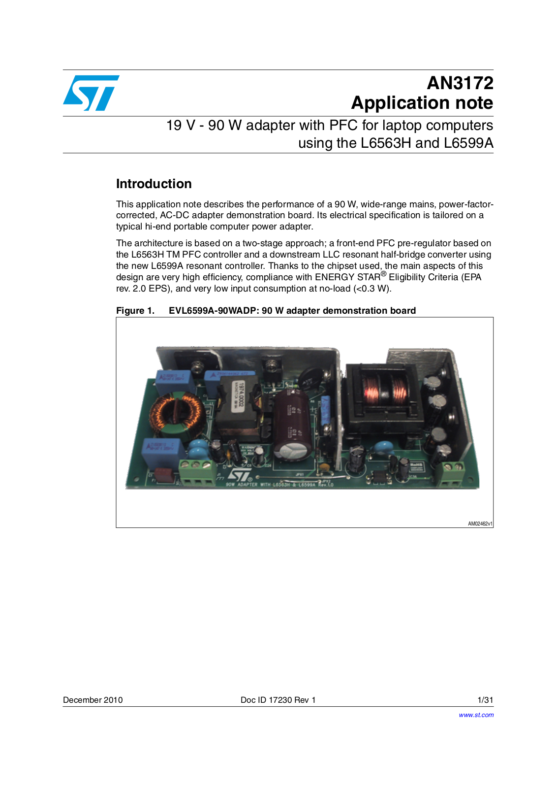
This application note describes the performance of a 90 W, wide-range mains, power-factor- corrected, AC-DC adapter demonstration board. Its electrical specification is tailored on a typical hi-end portable computer power adapter.

The architecture is based on a two-stage approach; a front-end PFC pre-regulator based on the L6563H TM PFC controller and a downstream LLC resonant half-bridge converter using the new L6599A resonant controller. Thanks to the chipset used, the main aspects of this design are very high efficiency, compliance with ENERGY STAR® Eligibility Criteria (EPA rev. 2.0 EPS), and very low input consumption at no-load (<0.3 W).

Figure 1. EVL6599A-90WADP: 90 W adapter demonstration board

December 2010

Doc ID 17230 Rev 1

1/31

www.st.com

Contents

AN3172


Contents

1

Main characteristics and circuit description . . . . . . . . . . . . . . . . . . . . .

5


1.1

Startup sequence . . . . . . . . . . . . . . . . . . . . . . . . . . . . . . . . . . . . . . . . . . . .

6


1.2

Brownout protection . . . . . . . . . . . . . . . . . . . . . . . . . . . . . . . . . . . . . . . . . .

6


1.3

Fast voltage feed forward . . . . . . . . . . . . . . . . . . . . . . . . . . . . . . . . . . . . . .

7


1.4

Resonant power stage . . . . . . . . . . . . . . . . . . . . . . . . . . . . . . . . . . . . . . . .

7


1.5

Output voltage feedback loop . . . . . . . . . . . . . . . . . . . . . . . . . . . . . . . . . . .

8


1.6

L6599A overload and short-circuit protection . . . . . . . . . . . . . . . . . . . . . . .

8


1.7

PFC overvoltage and open-loop protection . . . . . . . . . . . . . . . . . . . . . . . .

8


1.8

Standby power saving . . . . . . . . . . . . . . . . . . . . . . . . . . . . . . . . . . . . . . . .

9

2

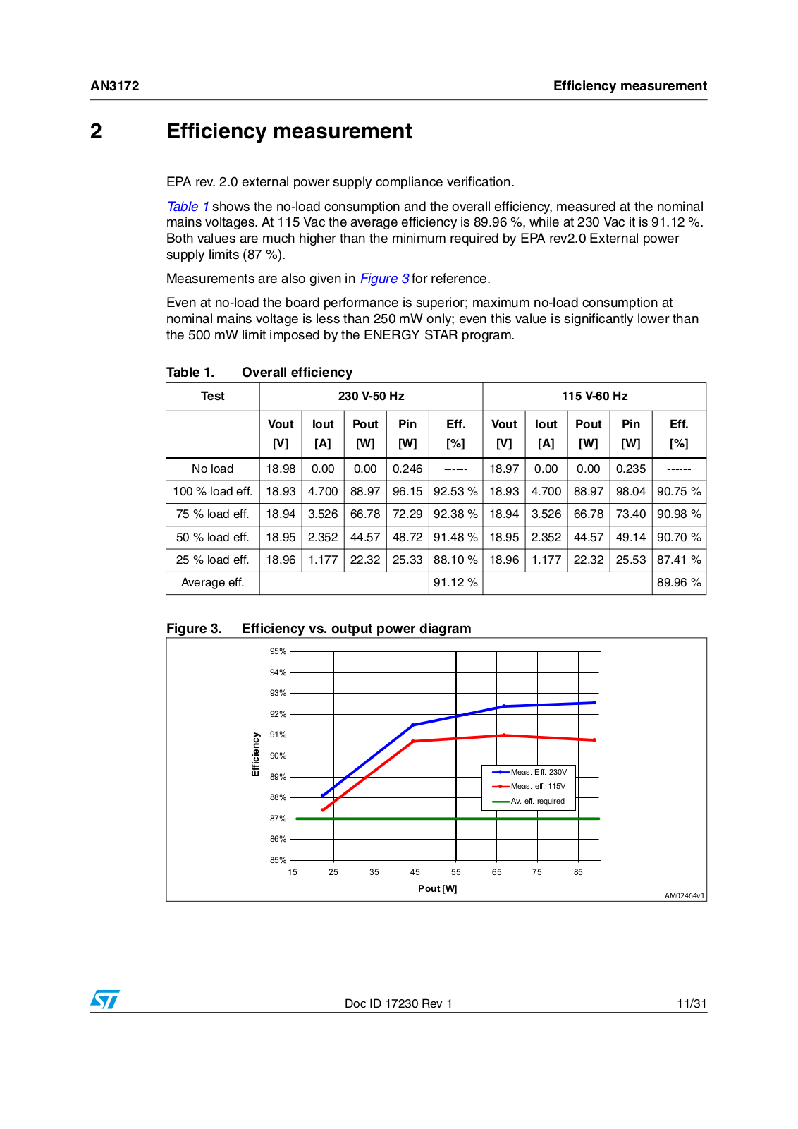
Efficiency measurement . . . . . . . . . . . . . . . . . . . . . . . . . . . . . . . . . . . . .

11


2.1

Light-load operation efficiency . . . . . . . . . . . . . . . . . . . . . . . . . . . . . . . . .

12

3

Harmonic content measurement . . . . . . . . . . . . . . . . . . . . . . . . . . . . . .

13

4

Functional check . . . . . . . . . . . . . . . . . . . . . . . . . . . . . . . . . . . . . . . . . . .

14


4.1

Standby and no-load operation . . . . . . . . . . . . . . . . . . . . . . . . . . . . . . . .

15


4.2

Overcurrent and short-circuit protection . . . . . . . . . . . . . . . . . . . . . . . . . .

16

5

Thermal map . . . . . . . . . . . . . . . . . . . . . . . . . . . . . . . . . . . . . . . . . . . . . .

18

6

Conducted emission pre-compliance test . . . . . . . . . . . . . . . . . . . . . .

20

7

BOM list . . . . . . . . . . . . . . . . . . . . . . . . . . . . . . . . . . . . . . . . . . . . . . . . . .

21

8

PFC coil specification . . . . . . . . . . . . . . . . . . . . . . . . . . . . . . . . . . . . . . .

26


8.1

Mechanical aspect and pin numbering . . . . . . . . . . . . . . . . . . . . . . . . . . .

27

9

Transformer specifications . . . . . . . . . . . . . . . . . . . . . . . . . . . . . . . . . .

28


9.1

Mechanical aspect and pin numbering . . . . . . . . . . . . . . . . . . . . . . . . . . .

29

10

Revision history . . . . . . . . . . . . . . . . . . . . . . . . . . . . . . . . . . . . . . . . . . .

30

2/31

Doc ID 17230 Rev 1

AN3172

List of figures


List of figures

Figure 1. EVL6599A-90WADP: 90 W adapter demonstration board . . . . . . . . . . . . . . . . . . . . . . . . . . 1 Figure 2. Electrical diagram . . . . . . . . . . . . . . . . . . . . . . . . . . . . . . . . . . . . . . . . . . . . . . . . . . . . . . . . 10 Figure 3. Efficiency vs. output power diagram . . . . . . . . . . . . . . . . . . . . . . . . . . . . . . . . . . . . . . . . . . 11 Figure 4. Light-load efficiency diagram . . . . . . . . . . . . . . . . . . . . . . . . . . . . . . . . . . . . . . . . . . . . . . . 12 Figure 5. Compliance to EN61000-3-2 at 230 Vac - 50 Hz, full load . . . . . . . . . . . . . . . . . . . . . . . . . 13 Figure 6. Compliance to JEITA-MITI at 100 Vac - 50 Hz, full load. . . . . . . . . . . . . . . . . . . . . . . . . . . 13 Figure 7. Resonant stage waveforms at 115 V - 60 Hz - full load . . . . . . . . . . . . . . . . . . . . . . . . . . . 14 Figure 8. Resonant stage waveforms at 230 V - 50 Hz - full load . . . . . . . . . . . . . . . . . . . . . . . . . . . 14 Figure 9. Rectifier waveforms . . . . . . . . . . . . . . . . . . . . . . . . . . . . . . . . . . . . . . . . . . . . . . . . . . . . . . 15 Figure 10. Startup waveforms . . . . . . . . . . . . . . . . . . . . . . . . . . . . . . . . . . . . . . . . . . . . . . . . . . . . . . . 15 Figure 11. No-load operation . . . . . . . . . . . . . . . . . . . . . . . . . . . . . . . . . . . . . . . . . . . . . . . . . . . . . . . . 15 Figure 12. No-load operation - detail . . . . . . . . . . . . . . . . . . . . . . . . . . . . . . . . . . . . . . . . . . . . . . . . . . 15 Figure 13. Transition full load to no-load at 265 Vac - 50 Hz. . . . . . . . . . . . . . . . . . . . . . . . . . . . . . . . 16 Figure 14. Transition no-load to full load at 265 Vac - 50 Hz. . . . . . . . . . . . . . . . . . . . . . . . . . . . . . . . 16 Figure 15. Short-circuit at full load and 115 Vac - 60 Hz . . . . . . . . . . . . . . . . . . . . . . . . . . . . . . . . . . . 17 Figure 16. Thermal map at 115 Vac - 60 Hz - full load . . . . . . . . . . . . . . . . . . . . . . . . . . . . . . . . . . . . 18 Figure 17. Thermal map at 230 Vac - 50 Hz - full load . . . . . . . . . . . . . . . . . . . . . . . . . . . . . . . . . . . . 18 Figure 18. CE Peak measurement at 115 Vac and full load . . . . . . . . . . . . . . . . . . . . . . . . . . . . . . . . 20 Figure 19. CE peak measurement at 230 Vac and full load . . . . . . . . . . . . . . . . . . . . . . . . . . . . . . . . 20 Figure 20. PFC coil electrical diagram . . . . . . . . . . . . . . . . . . . . . . . . . . . . . . . . . . . . . . . . . . . . . . . . . 26 Figure 21. PFC coil mechanical aspect . . . . . . . . . . . . . . . . . . . . . . . . . . . . . . . . . . . . . . . . . . . . . . . . 27 Figure 22. Transformer electrical diagram . . . . . . . . . . . . . . . . . . . . . . . . . . . . . . . . . . . . . . . . . . . . . . 28 Figure 23. Transformer overall drawing . . . . . . . . . . . . . . . . . . . . . . . . . . . . . . . . . . . . . . . . . . . . . . . . 29

Doc ID 17230 Rev 1

3/31

List of tables

AN3172


List of tables

Table 1. Overall efficiency . . . . . . . . . . . . . . . . . . . . . . . . . . . . . . . . . . . . . . . . . . . . . . . . . . . . . . . . 11 Table 2. Light-load efficiency . . . . . . . . . . . . . . . . . . . . . . . . . . . . . . . . . . . . . . . . . . . . . . . . . . . . . . 12 Table 3. Thermal maps reference points . . . . . . . . . . . . . . . . . . . . . . . . . . . . . . . . . . . . . . . . . . . . . 19 Table 4. EVL6599A-90WADP demonstration board: BOM list . . . . . . . . . . . . . . . . . . . . . . . . . . . . . 21 Table 5. PFC coil winding data . . . . . . . . . . . . . . . . . . . . . . . . . . . . . . . . . . . . . . . . . . . . . . . . . . . . . 26 Table 6. Transformer winding data . . . . . . . . . . . . . . . . . . . . . . . . . . . . . . . . . . . . . . . . . . . . . . . . . . 28 Table 7. Document revision history . . . . . . . . . . . . . . . . . . . . . . . . . . . . . . . . . . . . . . . . . . . . . . . . . 30

4/31

Doc ID 17230 Rev 1

AN3172

Main characteristics and circuit description


1 Main characteristics and circuit description

The main features of the SMPS are:

Universal input mains range: 90÷264 Vac - frequency 45 ÷ 65 Hz

Output voltage: 19 V at 4.75 A continuous operation

Mains harmonics: Acc. to EN61000-3-2 Class-D or JEITA-MITI Class-D

Standby mains consumption: <0.3 W at 230 Vac

Efficiency at nominal load: Better than 90 % at full load

EMI: According to EN55022-Class-B

Safety: According to EN60950

Dimensions: 65x151 mm, 25 mm component maximum height

PCB: Double side, 70 µm, FR-4, Mixed PTH/SMT

The circuit is composed of two stages; a front-end PFC using the L6563H and an LLC resonant converter based on the L6599A.

The PFC stage works as the pre-regulator and powers the resonant stage with a constant voltage of 400 V. The downstream converter operates only if the PFC is on and regulating its output voltage. In this way, the resonant stage can be optimized for a narrow input voltage range, improving the efficiency and the primary side power components.

Doc ID 17230 Rev 1

5/31

Main characteristics and circuit description

AN3172


1.1Startup sequence

As previously indicated, the PFC acts as master and the resonant stage can operate only if the PFC output is delivering its nominal output voltage. Therefore the circuit is designed so that at startup the PFC starts first, then the downstream converter turns-on. At the beginning, the L6563H is supplied by the integrated high voltage startup circuit; once the PFC starts switching, a charging pump connected to the PFC inductor supplies both PFC and resonant controllers. Once both stages have been activated, the controllers are also supplied by the auxiliary winding of the resonant transformer, assuring correct supply voltage, even during standby operation.

Because the L6563H integrated HV startup circuit is turned off, and therefore not dissipative during normal operation, it makes a significant contribution to power consumption reduction once the power supply operates at light-load, in agreement with standby worldwide standards currently required.

1.2Brownout protection

Brownout protection prevents the circuit from working with abnormal mains levels. It is easily achieved using the RUN pin (#12) of the L6563H; this pin is connected through a resistor divider to the VFF pin (#5) providing the information of the mains voltage peak value. An internal comparator allows IC operations if the mains level is correct, within the nominal limits. At startup, if the input voltage is below 90 Vac (typ.), circuit operations are inhibited.

The L6599A has similar protection on the LINE pin (#7). It is used to prevent the resonant converter from working with a too low input voltage which can cause incorrect capacitive mode operation. If the bulk voltage (PFC output) is below 380 V, the resonant stage startup is not allowed. The L6599A LINE pin internal comparator has a hysteresis allowing the turnon and turn-off voltage to be set independently. The turn-off threshold has been set to 300 V in order to avoid capacitive mode operation but allow the resonant stage to operate even in the case of mains sag and a consequent PFC output dip.

6/31

Doc ID 17230 Rev 1

AN3172

Main characteristics and circuit description


1.3Fast voltage feed forward

Voltage on the L6563H VFF pin (#5) has the same value as the peak value of the voltage on the MULT pin (#3) and it is generated by the RC network (R15+R26, C12) connected to VFF, completing an internal peak-holding circuit. This signal is necessary to derive information on the RMS input voltage to compensate the loop gain which is mains voltage dependent.

In general, if the VFF time constant is too small, the voltage generated is affected by a considerable amount of ripple at twice the mains frequency. Because the VFF signal is fed into the multiplier the excessive ripple causes distortion of the current reference resulting in high THD and poor PF. On the other hand, if the time constant is set too large there is a considerable delay in setting the right amount of feed-forward, resulting in excessive overshoot or undershoot of the pre-regulator's output voltage in response to large line voltage changes.

To overcome this issue, the L6563H implements the new Fast Voltage Feed Forward function. As soon as the voltage on the VFF pin decreases from a set threshold (40mV typically), a mains dip is assumed and an internal switch rapidly discharges the VFF capacitor via a 10 kΩ resistor. Thanks to this feature it is possible to set an RC circuit with a long time constant, assuring a low THD, but keeping a fast response to mains voltage variations.

1.4Resonant power stage

The downstream converter implements the ST L6599A, incorporating all the functions necessary to properly control the resonant converter with a 50 percent fixed duty cycle and working with variable frequency.

The transformer uses the integrated magnetic approach, incorporating the resonant series inductance. Therefore, no additional external coil is needed for the resonance.

The transformer configuration chosen for the secondary winding is centre tap and makes use of a couple of power schottky rectifiers p/n STPS30H60CFP. A small LC filter has been added on the output, filtering the high frequency ripple.

D15, R56, R62, R65, R66, Q5, and Q6 implement an output voltage “fast discharge” circuit, quickly discharging the output capacitors when the converter is turned off. It has been implemented to quickly decrease the residual output voltage once the converter is turned off at no-load.

Doc ID 17230 Rev 1

7/31

Main characteristics and circuit description

AN3172


1.5Output voltage feedback loop

The feedback loop is implemented by means of a typical circuit using a TL431 modulating the current in the optocoupler diode.

On the primary side, R34 - connecting pin RFMIN (#4) to the optocoupler’s phototransistor - closes the feedback loop and its value sets the maximum switching frequency at about 130 kHz. This value has been chosen to limit the switching losses at light-load operation. R31, connecting the same pin to ground, sets the minimum switching frequency. The R-C series R44 and C18 sets both soft-start maximum frequency and duration.

1.6L6599A overload and short-circuit protection

The current into the primary winding is sensed by the lossless circuit R41, C27, D11, D10, R39, and C25 and it is fed into the ISEN pin (#6). In the case of overcurrent, the voltage on the pin overpasses an internal comparator threshold (0.8 V), triggering a protection sequence. The capacitor (C45) connected to the DELAY pin (#2) is charged by an internal 150 µA current generator and is slowly discharged by the external resistor (R24). If the voltage on the pin reaches 2 V, the soft-start capacitor is completely discharged so that the switching frequency is pushed to its maximum value. As the voltage on the pin exceeds 3.5 V the IC stops switching and the internal generator is turned off, so that the voltage on the pin decays because of the external resistor. The IC is soft-restarted as the voltage drops below 0.3 V. In this way, under short-circuit conditions, the converter works intermittently with very low average input power.

1.7PFC overvoltage and open-loop protection

Both circuit stages, PFC and resonant, are equipped with their own overvoltage protections.

The L6563H PFC controller monitors its output voltage via the resistor divider connected to a dedicated pin (PFC_OK, #7) protecting the circuit in the case of loop failures or disconnection of the feedback loop divider. In the case where a fault condition is detected, the PFC_OK circuitry latches the L6563H operations and, by means of the PWM_LATCH pin (#8), it also latches the L6599A, via the DIS pin (#8). The converter is kept latched by the L6563H HV circuit that supplies the IC charging the Vcc capacitor periodically. To resume converter operation mains restart is necessary.

8/31

Doc ID 17230 Rev 1

AN3172

Main characteristics and circuit description


1.8Standby power saving

The board implements a burst-mode function allowing a significant power saving during light-load operation.

The L6599A’s STBY pin (#5) senses the optocoupler’s collector voltage which is related to the feedback control and is proportional to the output load. This signal is compared to an internal reference (1.24 V); if the load decreases and the voltage on the STBY pin goes lower than the reference, the IC enters an idle state and its quiescent current is reduced. Once the voltage exceeds the reference by 50 mV, the controller restarts switching. Burstmode operation load threshold can be programmed by properly choosing the resistor connecting the optocoupler to the RFMIN pin (R34). On this board the controller operates in burst-mode if the load falls below ~15 W.

The L6563H implements its own burst-mode function. If the COMP voltage falls below 2.5 V, the IC stops switching, causing an output voltage decrease, as a consequence the COMP voltage rises again and the IC restarts switching.

In order to achieve a better load transient response, the PFC burst-mode operation is partially forced by the resonant converter; once the L6599A stops switching due to load drops, its PFC_STOP pin pulls down the L6563H’s PFC_OK pin, disabling PFC switching. Thanks to this solution, the PFC is forced into idle state when the resonant stage is not switching and rapidly wakes-up when the downstream converter restarts switching. This solution prevents a significant drop of the bulk voltage in the case of abrupt load rising.

Doc ID 17230 Rev 1

9/31

ST AN3172 Application note

10/31


'


diagram Electrical .2Figure

circuit and characteristicsMain


1


9DF

)

&

/


'


5


)86( 7$

Q )


*%8-


17& 5 6


a


&


&


'


Q )


&


5

5

&


Q)


/


677+ /


B


Q)


0HJ

0

X)


a


&


&


Q )


&


Q)


&


-


5


'


Q )


Q)


0.'6


5


//


5

5


0HJ

0


'


&


//

X)


5


0


'


4


=


//

5

5


%& &


0HJ

0


5


3&% 5(9


'


5


0


//


.


'


%=9 &


&


5


5


5


description


.


Q)


.


.


8


5


4


/ +


.


'

5


5

5


67) 10 1


&

5


&

&


1 0

1 0


.


.


,19


9&&


Q)

.


X)

Q)


Doc


&203


*'


+6


5


+($7 6,1.


08/7


*1'


5

5

5


5

&


5


.


ID


.


&6


=&'


Q )


5


9))


581


.


&


17230


5

5

5


4

S)


&


7%2

3:0 6723


.


5

5


5


S)


&

%& &


7


.


'


3)& 2.


1&


Q )


-


&


//


'


/


0.'6


Q)


3:0 /$7&+

+96


5


6736 + &)3


Rev


&


.


X)


5


5


5


.


&


&

&


5


1 0


9 #$


'


Q)


X)

X)


1


//


&

&


4


X)

Q)


5


67) 10 1


5

5


+6


0HJ


'


5


5

.


+($7 6,1.


.


6736 + &)3


5


&

5


Q)

0HJ


'


1 0


8


&


//


'


5

'


/$'


Q)


4


%=9 &


.

//


4


&66

9%227


67) 10 1


1 0


5


5

5


5

5

&


'(/$<

+9*


5

5


.

.


'


.


.


0

1


1 0


&


&


&)

287


5


4


&


S)


.


X)


%& &


5


1 0


5)0,1

1&


5


4


5


1 0

5

%& &


5


1 0


5


5


67%<

9&&


-3;


.


.


.


&


-3;

8


5


4


-XPSHU


5


Q)


,6(1

/9*


'

-XPSHU 6)+$

.


%& &


'


5


//

5


&


5


5


1 0


/,1(

*1'


&


X)


.


5

&


X)


',6

3)& 6723

&


&


5


5

S)


5


'


'


5


Q)


Q)


.


'


%=9 %


.


1 0


5


'


%=9 &


//


5


5

&

&


&


1 0


.

Q)

Q )


5


Q)

5


'

5


.


-3;


!


6736 /$


5(9


-XPSHU


&


5


V-


5


AN3172


5

Q)


.

.


8


5


&


7/$,=


X)


Loading...
+ 21 hidden pages