ST AN3160 APPLICATION NOTE

AN3160

Application note

Wide range [90 - 265] input, single output [12 V-6 W] VIPer15 demonstration board (STEVALVIP15L-6W)

Introduction

The new VIPer15 device integrates two components in the same package: an advanced BCD6 technology PWM controller and an 800 V avalanche rugged vertical power MOSFET. The device is suitable for realizing an offline power converter using flyback topologies with variable frequency control strategies, commonly known as quasi-resonant flyback. The device is able to handle up to about 6 W in wide input voltage range (88 VAC 264 VAC) converters and up to about 10 W in European input voltage range converters. The main advantage of using a QR (quasi-resonant) approach is that it makes use of the otherwise undesirable parasitic drain capacitance to generate a zero-voltage condition that minimizes turn-on losses of the MOSFET.

In mains operated applications, due to the ripple appearing across the input bulk capacitor, the switching frequency is modulated at twice the mains frequency and this causes the EMI spectrum to be spread over frequency bands, rather than being concentrated on single frequency values. Especially when measuring conducted emissions with the average detection method, the level reduction can be of several dBµV.

The way the system processes power does not change, therefore the designer's experience with a standard flyback can be fully exploited and there is very little additional know-how needed.

The proposed solution has the advantage of using few external components providing several protections and very low standby consumption.

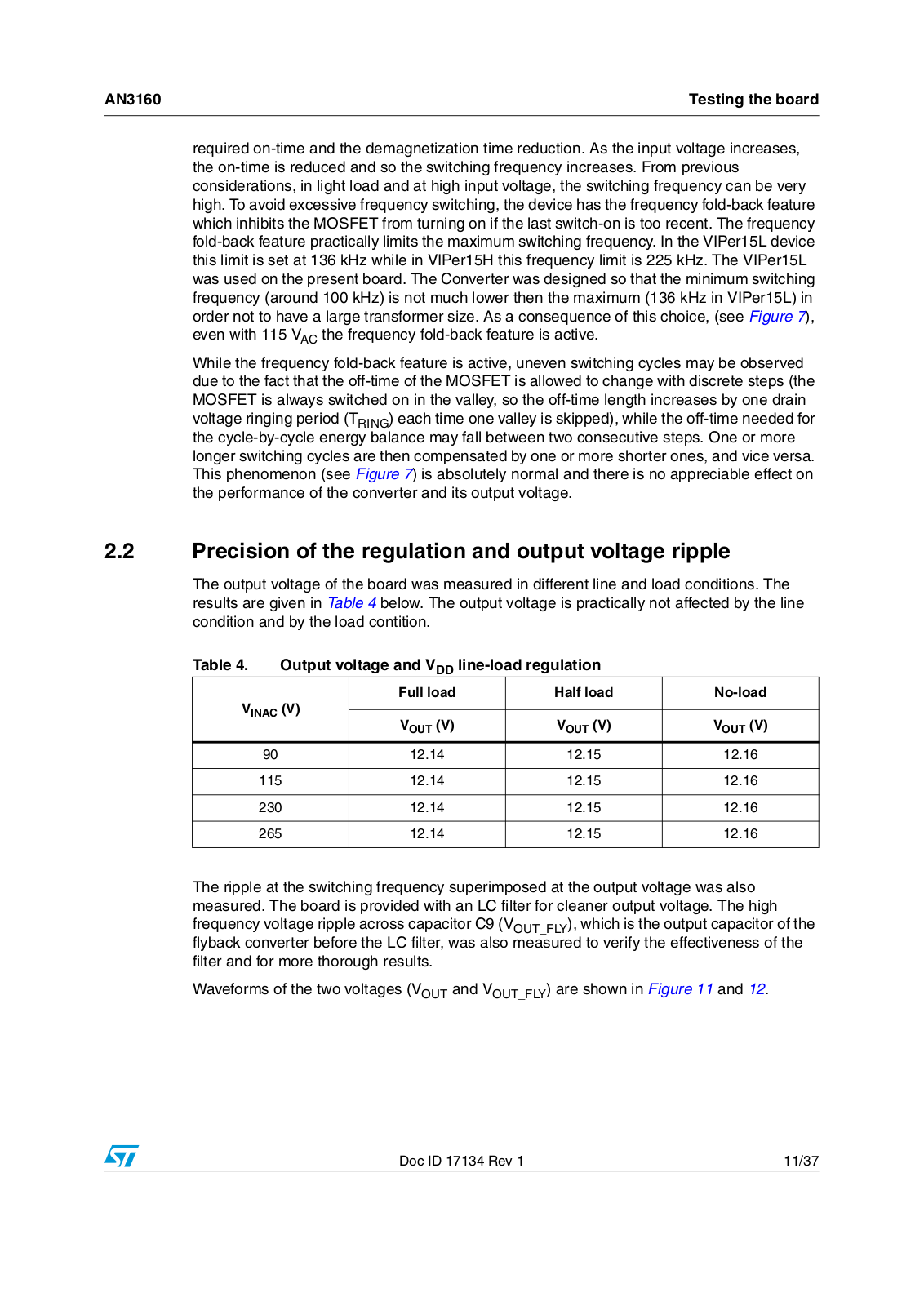
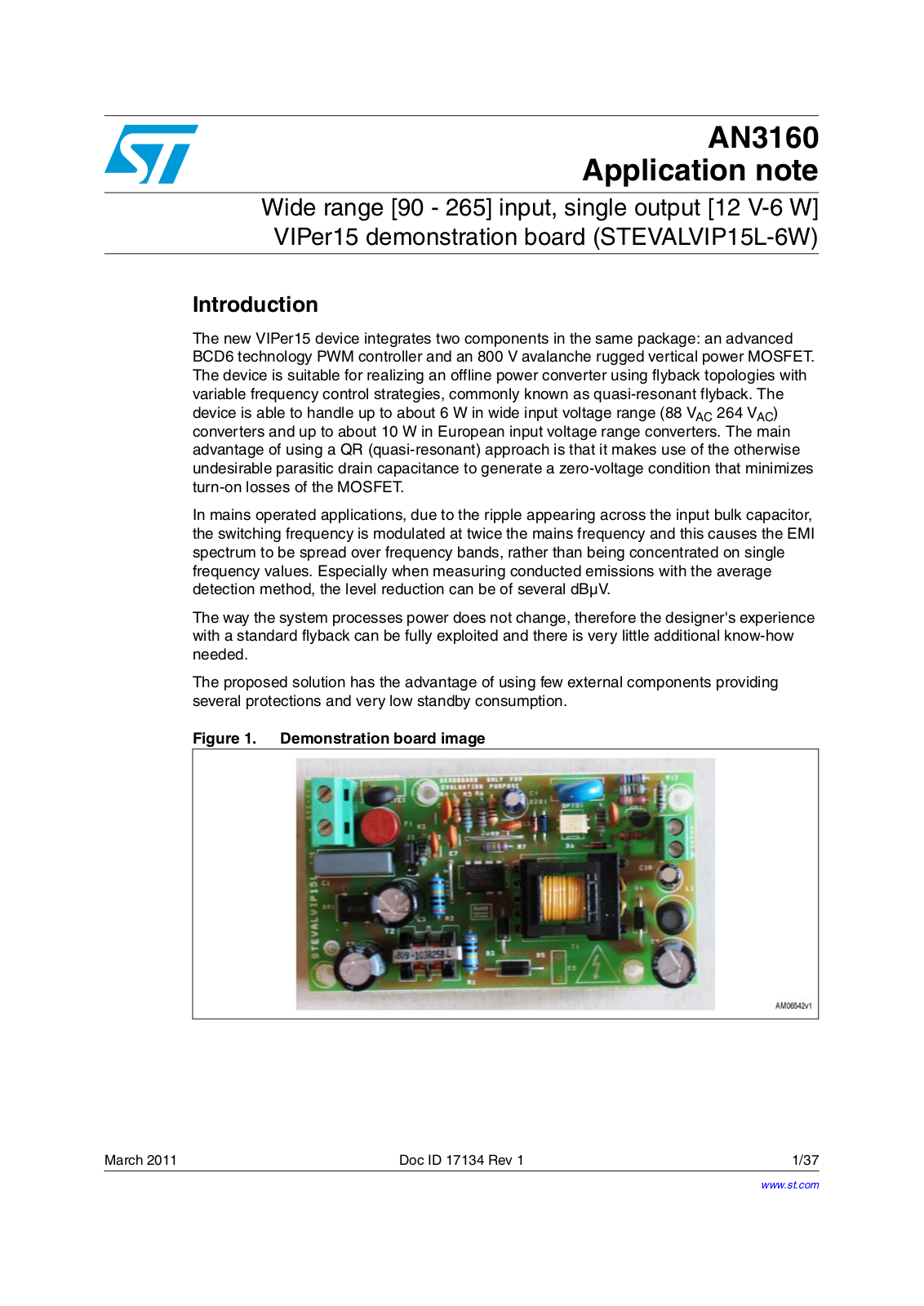
Figure 1. Demonstration board image

March 2011

Doc ID 17134 Rev 1

1/37

www.st.com

Contents

AN3160


Contents

1

Board description . . . . . . . . . . . . . . . . . . . . . . . . . . . . . . . . . . . . . . . . . . .

5


1.1

Electrical specifications . . . . . . . . . . . . . . . . . . . . . . . . . . . . . . . . . . . . . . .

5


1.2

Schematic and bom list . . . . . . . . . . . . . . . . . . . . . . . . . . . . . . . . . . . . . . .

6


1.3

Transformer . . . . . . . . . . . . . . . . . . . . . . . . . . . . . . . . . . . . . . . . . . . . . . . .

8

2

Testing the board . . . . . . . . . . . . . . . . . . . . . . . . . . . . . . . . . . . . . . . . . .

10


2.1

Typical board waveforms . . . . . . . . . . . . . . . . . . . . . . . . . . . . . . . . . . . . .

10


2.2

Precision of the regulation and output voltage ripple . . . . . . . . . . . . . . . .

11


2.3

Efficiency . . . . . . . . . . . . . . . . . . . . . . . . . . . . . . . . . . . . . . . . . . . . . . . . .

14


2.4

Light load performance . . . . . . . . . . . . . . . . . . . . . . . . . . . . . . . . . . . . . . .

18

2.4.1 No-load condition . . . . . . . . . . . . . . . . . . . . . . . . . . . . . . . . . . . . . . . . . . 18 2.4.2 Low load performance . . . . . . . . . . . . . . . . . . . . . . . . . . . . . . . . . . . . . . 19

2.5

Test equipment and measurement of efficiency and input power . . . . . .

22


2.5.1

Measuring input power notes . . . . . . . . . . . . . . . . . . . . . . . . . . . . . . . . .

22

2.6 Overload protection . . . . . . . . . . . . . . . . . . . . . . . . . . . . . . . . . . . . . . . . . 24 2.7 Voltage feed-forward function . . . . . . . . . . . . . . . . . . . . . . . . . . . . . . . . . . 26 2.8 Secondary winding short-circuit protection . . . . . . . . . . . . . . . . . . . . . . . 27 2.9 Output overvoltage protection . . . . . . . . . . . . . . . . . . . . . . . . . . . . . . . . . 28 2.10 Brownout protection . . . . . . . . . . . . . . . . . . . . . . . . . . . . . . . . . . . . . . . . . 30 2.11 EMI measurements . . . . . . . . . . . . . . . . . . . . . . . . . . . . . . . . . . . . . . . . . 33

3

Conclusions . . . . . . . . . . . . . . . . . . . . . . . . . . . . . . . . . . . . . . . . . . . . . . .

34

4

References . . . . . . . . . . . . . . . . . . . . . . . . . . . . . . . . . . . . . . . . . . . . . . . .

35

5

Revision history . . . . . . . . . . . . . . . . . . . . . . . . . . . . . . . . . . . . . . . . . . .

36

2/37

Doc ID 17134 Rev 1

AN3160

List of tables


List of tables

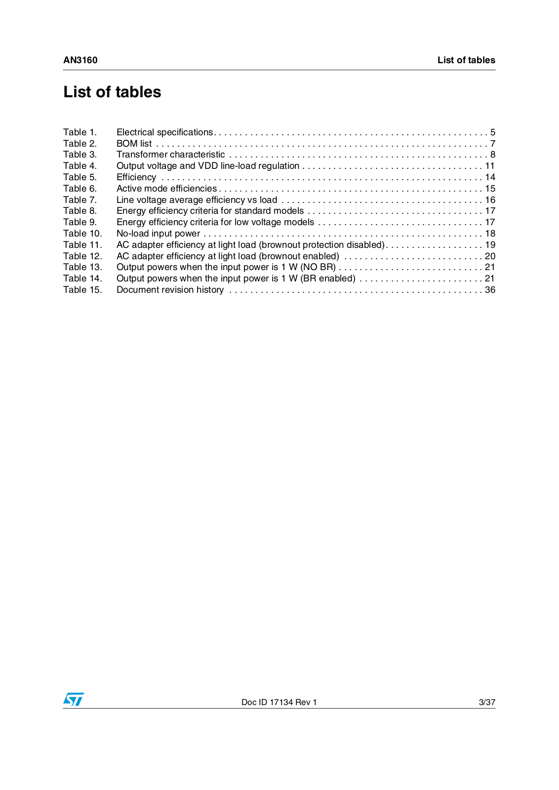
Table 1. Electrical specifications. . . . . . . . . . . . . . . . . . . . . . . . . . . . . . . . . . . . . . . . . . . . . . . . . . . . . 5 Table 2. BOM list . . . . . . . . . . . . . . . . . . . . . . . . . . . . . . . . . . . . . . . . . . . . . . . . . . . . . . . . . . . . . . . . 7 Table 3. Transformer characteristic . . . . . . . . . . . . . . . . . . . . . . . . . . . . . . . . . . . . . . . . . . . . . . . . . . 8 Table 4. Output voltage and VDD line-load regulation . . . . . . . . . . . . . . . . . . . . . . . . . . . . . . . . . . . 11 Table 5. Efficiency . . . . . . . . . . . . . . . . . . . . . . . . . . . . . . . . . . . . . . . . . . . . . . . . . . . . . . . . . . . . . . 14 Table 6. Active mode efficiencies . . . . . . . . . . . . . . . . . . . . . . . . . . . . . . . . . . . . . . . . . . . . . . . . . . . 15 Table 7. Line voltage average efficiency vs load . . . . . . . . . . . . . . . . . . . . . . . . . . . . . . . . . . . . . . . 16 Table 8. Energy efficiency criteria for standard models . . . . . . . . . . . . . . . . . . . . . . . . . . . . . . . . . . 17 Table 9. Energy efficiency criteria for low voltage models . . . . . . . . . . . . . . . . . . . . . . . . . . . . . . . . 17 Table 10. No-load input power . . . . . . . . . . . . . . . . . . . . . . . . . . . . . . . . . . . . . . . . . . . . . . . . . . . . . . 18 Table 11. AC adapter efficiency at light load (brownout protection disabled). . . . . . . . . . . . . . . . . . . 19 Table 12. AC adapter efficiency at light load (brownout enabled) . . . . . . . . . . . . . . . . . . . . . . . . . . . 20 Table 13. Output powers when the input power is 1 W (NO BR) . . . . . . . . . . . . . . . . . . . . . . . . . . . . 21 Table 14. Output powers when the input power is 1 W (BR enabled) . . . . . . . . . . . . . . . . . . . . . . . . 21 Table 15. Document revision history . . . . . . . . . . . . . . . . . . . . . . . . . . . . . . . . . . . . . . . . . . . . . . . . . 36

Doc ID 17134 Rev 1

3/37

List of figures

AN3160


List of figures

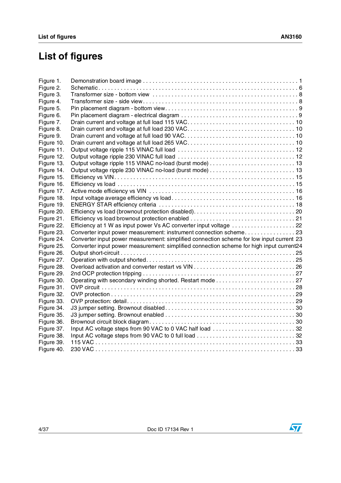
Figure 1. Demonstration board image . . . . . . . . . . . . . . . . . . . . . . . . . . . . . . . . . . . . . . . . . . . . . . . . . 1 Figure 2. Schematic . . . . . . . . . . . . . . . . . . . . . . . . . . . . . . . . . . . . . . . . . . . . . . . . . . . . . . . . . . . . . . . 6 Figure 3. Transformer size - bottom view . . . . . . . . . . . . . . . . . . . . . . . . . . . . . . . . . . . . . . . . . . . . . . 8 Figure 4. Transformer size - side view. . . . . . . . . . . . . . . . . . . . . . . . . . . . . . . . . . . . . . . . . . . . . . . . . 8 Figure 5. Pin placement diagram - bottom view. . . . . . . . . . . . . . . . . . . . . . . . . . . . . . . . . . . . . . . . . . 9 Figure 6. Pin placement diagram - electrical diagram . . . . . . . . . . . . . . . . . . . . . . . . . . . . . . . . . . . . . 9 Figure 7. Drain current and voltage at full load 115 VAC. . . . . . . . . . . . . . . . . . . . . . . . . . . . . . . . . . 10 Figure 8. Drain current and voltage at full load 230 VAC. . . . . . . . . . . . . . . . . . . . . . . . . . . . . . . . . . 10 Figure 9. Drain current and voltage at full load 90 VAC. . . . . . . . . . . . . . . . . . . . . . . . . . . . . . . . . . . 10 Figure 10. Drain current and voltage at full load 265 VAC. . . . . . . . . . . . . . . . . . . . . . . . . . . . . . . . . . 10 Figure 11. Output voltage ripple 115 VINAC full load . . . . . . . . . . . . . . . . . . . . . . . . . . . . . . . . . . . . . 12 Figure 12. Output voltage ripple 230 VINAC full load . . . . . . . . . . . . . . . . . . . . . . . . . . . . . . . . . . . . . 12 Figure 13. Output voltage ripple 115 VINAC no-load (burst mode) . . . . . . . . . . . . . . . . . . . . . . . . . . . 13 Figure 14. Output voltage ripple 230 VINAC no-load (burst mode) . . . . . . . . . . . . . . . . . . . . . . . . . . . 13 Figure 15. Efficiency vs VIN. . . . . . . . . . . . . . . . . . . . . . . . . . . . . . . . . . . . . . . . . . . . . . . . . . . . . . . . . 15 Figure 16. Efficiency vs load . . . . . . . . . . . . . . . . . . . . . . . . . . . . . . . . . . . . . . . . . . . . . . . . . . . . . . . . 15 Figure 17. Active mode efficiency vs VIN . . . . . . . . . . . . . . . . . . . . . . . . . . . . . . . . . . . . . . . . . . . . . . 16 Figure 18. Input voltage average efficiency vs load. . . . . . . . . . . . . . . . . . . . . . . . . . . . . . . . . . . . . . . 16 Figure 19. ENERGY STAR efficiency criteria . . . . . . . . . . . . . . . . . . . . . . . . . . . . . . . . . . . . . . . . . . . 18 Figure 20. Efficiency vs load (brownout protection disabled). . . . . . . . . . . . . . . . . . . . . . . . . . . . . . . . 20 Figure 21. Efficiency vs load brownout protection enabled . . . . . . . . . . . . . . . . . . . . . . . . . . . . . . . . . 21 Figure 22. Efficiency at 1 W as input power Vs AC converter input voltage . . . . . . . . . . . . . . . . . . . . 22 Figure 23. Converter input power measurement: instrument connection scheme. . . . . . . . . . . . . . . . 23 Figure 24. Converter input power measurement: simplified connection scheme for low input current 23 Figure 25. Converter input power measurement: simplified connection scheme for high input current24 Figure 26. Output short-circuit . . . . . . . . . . . . . . . . . . . . . . . . . . . . . . . . . . . . . . . . . . . . . . . . . . . . . . . 25 Figure 27. Operation with output shorted. . . . . . . . . . . . . . . . . . . . . . . . . . . . . . . . . . . . . . . . . . . . . . . 25 Figure 28. Overload activation and converter restart vs VIN . . . . . . . . . . . . . . . . . . . . . . . . . . . . . . . . 26 Figure 29. 2nd OCP protection tripping . . . . . . . . . . . . . . . . . . . . . . . . . . . . . . . . . . . . . . . . . . . . . . . . 27 Figure 30. Operating with secondary winding shorted. Restart mode . . . . . . . . . . . . . . . . . . . . . . . . . 27 Figure 31. OVP circuit . . . . . . . . . . . . . . . . . . . . . . . . . . . . . . . . . . . . . . . . . . . . . . . . . . . . . . . . . . . . . 28 Figure 32. OVP protection . . . . . . . . . . . . . . . . . . . . . . . . . . . . . . . . . . . . . . . . . . . . . . . . . . . . . . . . . . 29 Figure 33. OVP protection: detail. . . . . . . . . . . . . . . . . . . . . . . . . . . . . . . . . . . . . . . . . . . . . . . . . . . . . 29 Figure 34. J3 jumper setting. Brownout disabled. . . . . . . . . . . . . . . . . . . . . . . . . . . . . . . . . . . . . . . . . 30 Figure 35. J3 jumper setting. Brownout enabled . . . . . . . . . . . . . . . . . . . . . . . . . . . . . . . . . . . . . . . . . 30 Figure 36. Brownout circuit block diagram. . . . . . . . . . . . . . . . . . . . . . . . . . . . . . . . . . . . . . . . . . . . . . 30 Figure 37. Input AC voltage steps from 90 VAC to 0 VAC half load . . . . . . . . . . . . . . . . . . . . . . . . . . 32 Figure 38. Input AC voltage steps from 90 VAC to 0 full load . . . . . . . . . . . . . . . . . . . . . . . . . . . . . . . 32 Figure 39. 115 VAC . . . . . . . . . . . . . . . . . . . . . . . . . . . . . . . . . . . . . . . . . . . . . . . . . . . . . . . . . . . . . . . 33 Figure 40. 230 VAC . . . . . . . . . . . . . . . . . . . . . . . . . . . . . . . . . . . . . . . . . . . . . . . . . . . . . . . . . . . . . . . 33

4/37

Doc ID 17134 Rev 1

AN3160

Board description


1 Board description

1.1Electrical specifications

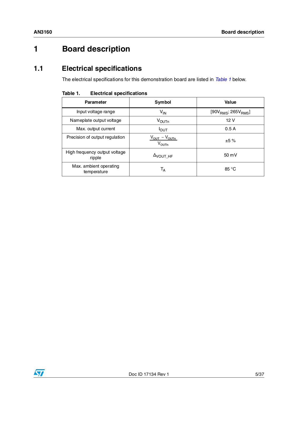
The electrical specifications for this demonstration board are listed in Table 1 below.

Table 1.

Electrical specifications


Parameter


Symbol

Value


Input voltage range


VIN

[90VRMS; 265VRMS]

Nameplate output voltage


VOUTn

12 V

Max. output current


IOUT

0.5 A

Precision of output regulation


±5 %


High frequency output voltage


VOUT_HF

50 mV


ripple


Max. ambient operating


TA

85 °C


temperature


Doc ID 17134 Rev 1

5/37

Board description

AN3160


1.2Schematic and bom list

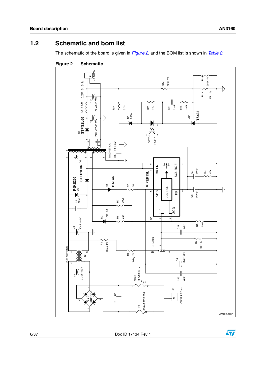
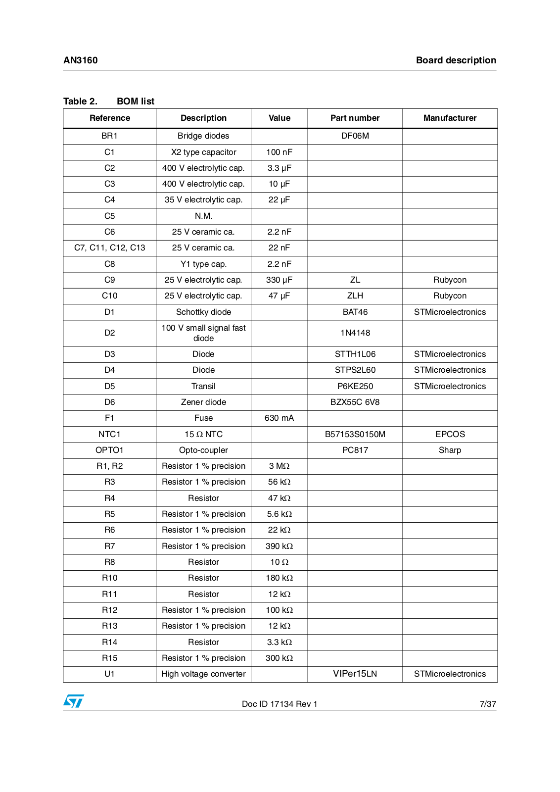
The schematic of the board is given in Figure 2, and the BOM list is shown in Table 2.

Figure 2.


Schematic


&21


N


5

N


9$

-


5


/ X+


& &

=/+ X) 9 =/ X) 9


5


N


9]


5

N


&

Q)


5

N


76

5

N


6736 /


'


95


'


2372

3&


7


0$*1(7,&$

& < Q)


'


9'' '5$,1


6285&(


3 .(

'


& 1 0 677+ /


%$7


& &

Q) Q)

5

N


'

5

N

5


9,3(5 /


&21752/

)%


&

X) 9


'


1


5

N


8


%5


=&'

&

Q)


5

N


%8 5 %/


5


0HJ


-803(5


5

N


X) 9


7


5

0HJ


-


&


&


X) 9


17&

2KP 17&

W


&

Q)


%5


-


&21 PP


P$ 067


%5,'*(


& ;


)


!-V

6/37

Doc ID 17134 Rev 1

AN3160


Board description


Table 2.

BOM list


Reference

Description

Value

Part number

Manufacturer


BR1

Bridge diodes


DF06M


C1

X2 type capacitor

100 nF


C2

400 V electrolytic cap.

3.3 µF


C3

400 V electrolytic cap.

10 µF


C4

35 V electrolytic cap.

22 µF


C5

N.M.


C6

25 V ceramic ca.

2.2 nF


C7, C11, C12, C13

25 V ceramic ca.

22 nF


C8

Y1 type cap.

2.2 nF


C9

25 V electrolytic cap.

330 µF

ZL

Rubycon


C10

25 V electrolytic cap.

47 µF

ZLH

Rubycon


D1

Schottky diode


BAT46

STMicroelectronics


D2

100 V small signal fast


1N4148


diode


D3

Diode


STTH1L06

STMicroelectronics


D4

Diode


STPS2L60

STMicroelectronics


D5

Transil


P6KE250

STMicroelectronics


D6

Zener diode


BZX55C 6V8


F1

Fuse

630 mA


NTC1

15 Ω NTC


B57153S0150M

EPCOS


OPTO1

Opto-coupler


PC817

Sharp


R1, R2

Resistor 1 % precision

3 MΩ


R3

Resistor 1 % precision

56 kΩ


R4

Resistor

47 kΩ


R5

Resistor 1 % precision

5.6 kΩ


R6

Resistor 1 % precision

22 kΩ


R7

Resistor 1 % precision

390 kΩ


R8

Resistor

10 Ω


R10

Resistor

180 kΩ


R11

Resistor

12 kΩ


R12

Resistor 1 % precision

100 kΩ


R13

Resistor 1 % precision

12 kΩ


R14

Resistor

3.3 kΩ


R15

Resistor 1 % precision

300 kΩ


U1

High voltage converter


VIPer15LN

STMicroelectronics


Doc ID 17134 Rev 1

7/37

Board description


AN3160


Table 2.

BOM list (continued)


Reference

Description

Value

Part number

Manufacturer


VR1

Voltage reference


TS431

STMicroelectronics


T1

Transformer


1335.0082 Rev. 1

MAGNETICA


T2

CMC for line filter


BU9-103R25BL

Coilcraft


1.3Transformer

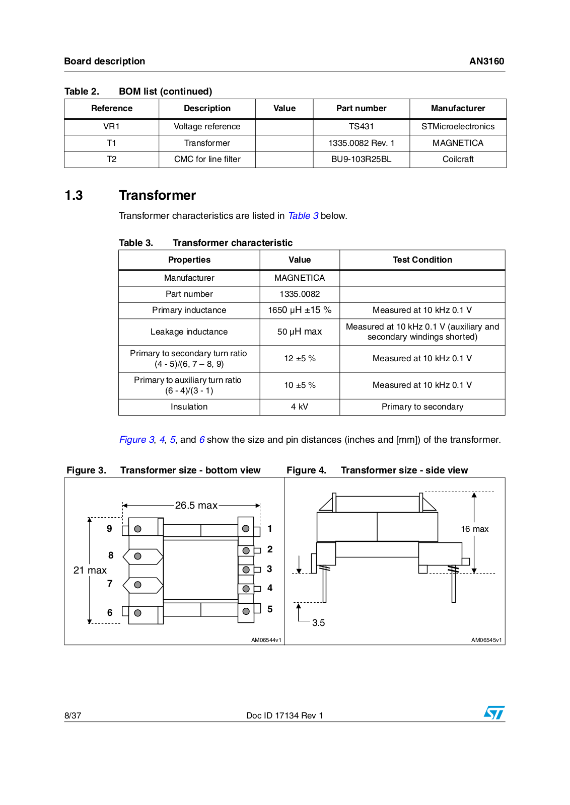
Transformer characteristics are listed in Table 3 below.

Table 3.

Transformer characteristic


Properties

Value

Test Condition


Manufacturer

MAGNETICA


Part number

1335.0082


Primary inductance

1650 µH ±15 %

Measured at 10 kHz 0.1 V


Leakage inductance

50 µH max

Measured at 10 kHz 0.1 V (auxiliary and

secondary windings shorted)


Primary to secondary turn ratio

12 ±5 %

Measured at 10 kHz 0.1 V


(4 - 5)/(6, 7 – 8, 9)


Primary to auxiliary turn ratio

10 ±5 %

Measured at 10 kHz 0.1 V


(6 - 4)/(3 - 1)


Insulation

4 kV

Primary to secondary


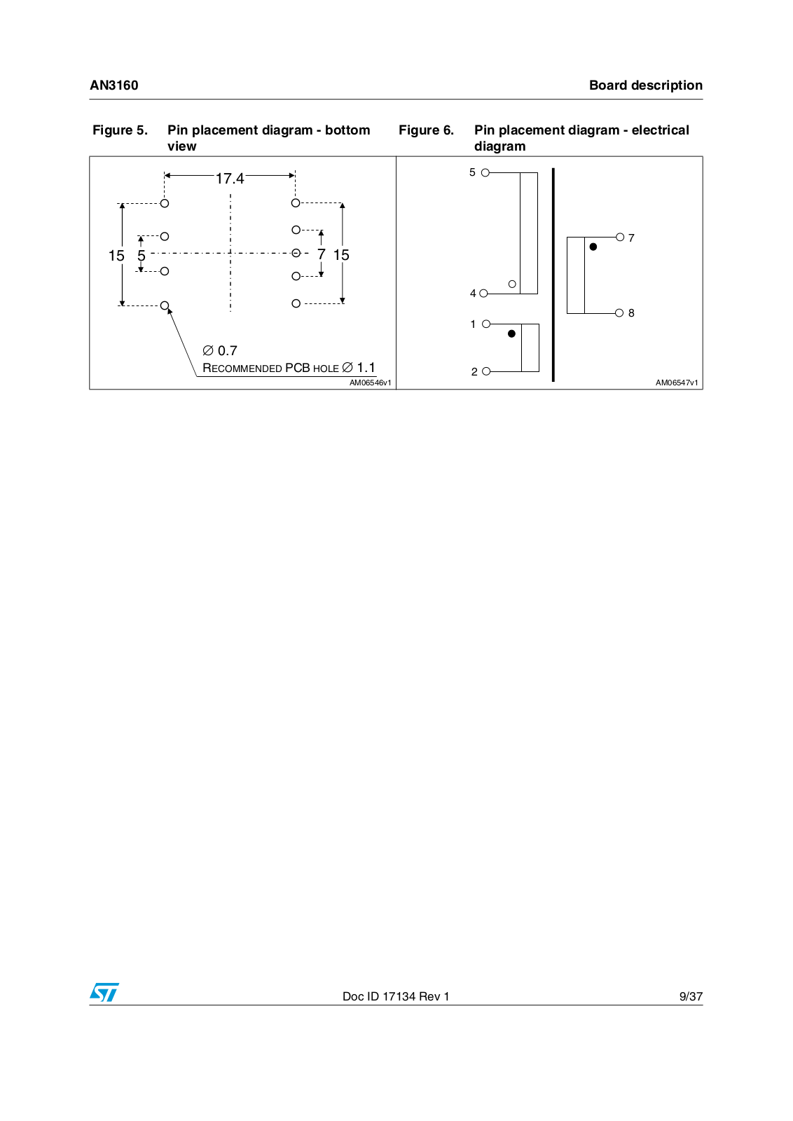
Figure 3, 4, 5, and 6 show the size and pin distances (inches and [mm]) of the transformer.

Figure 3. Transformer size - bottom view

Figure 4. Transformer size - side view

MAX


MAX


MAX


!-V

!-V

8/37

Doc ID 17134 Rev 1

AN3160


Board description

Figure 5.

Pin placement diagram - bottom

Figure 6.

Pin placement diagram - electrical


view


diagram


2%#/--%.$%$ 0#" (/,%


!-V


!-V

Doc ID 17134 Rev 1

9/37

ST AN3160 APPLICATION NOTE

Testing the board

AN3160


2 Testing the board

2.1Typical board waveforms

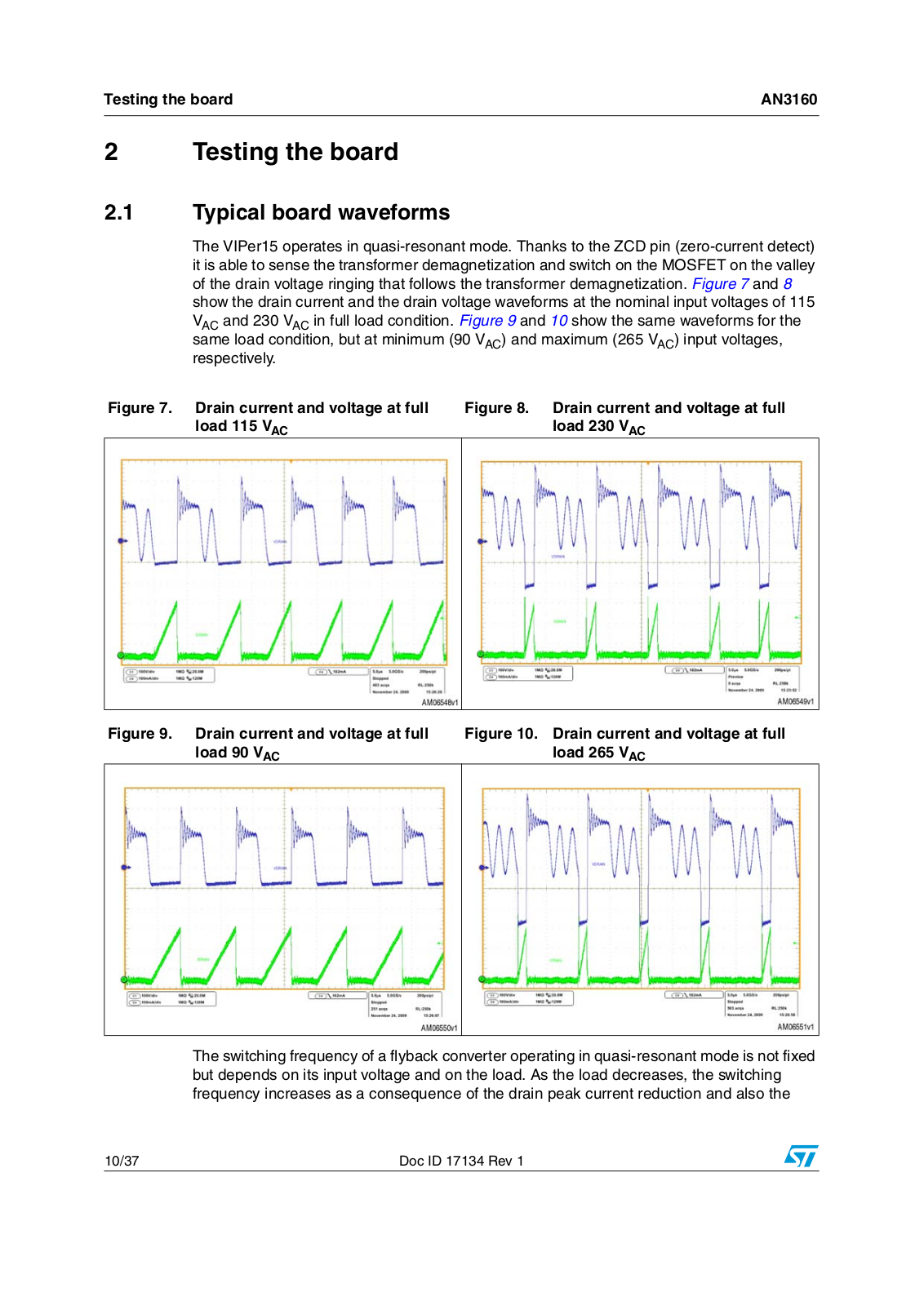
The VIPer15 operates in quasi-resonant mode. Thanks to the ZCD pin (zero-current detect) it is able to sense the transformer demagnetization and switch on the MOSFET on the valley of the drain voltage ringing that follows the transformer demagnetization. Figure 7 and 8 show the drain current and the drain voltage waveforms at the nominal input voltages of 115 VAC and 230 VAC in full load condition. Figure 9 and 10 show the same waveforms for the same load condition, but at minimum (90 VAC) and maximum (265 VAC) input voltages, respectively.

Figure 7. Drain current and voltage at full load 115 VAC

Figure 8. Drain current and voltage at full load 230 VAC

Figure 9. Drain current and voltage at full load 90 VAC

Figure 10. Drain current and voltage at full load 265 VAC

The switching frequency of a flyback converter operating in quasi-resonant mode is not fixed but depends on its input voltage and on the load. As the load decreases, the switching frequency increases as a consequence of the drain peak current reduction and also the

10/37

Doc ID 17134 Rev 1

AN3160

Testing the board


required on-time and the demagnetization time reduction. As the input voltage increases, the on-time is reduced and so the switching frequency increases. From previous considerations, in light load and at high input voltage, the switching frequency can be very high. To avoid excessive frequency switching, the device has the frequency fold-back feature which inhibits the MOSFET from turning on if the last switch-on is too recent. The frequency fold-back feature practically limits the maximum switching frequency. In the VIPer15L device this limit is set at 136 kHz while in VIPer15H this frequency limit is 225 kHz. The VIPer15L was used on the present board. The Converter was designed so that the minimum switching frequency (around 100 kHz) is not much lower then the maximum (136 kHz in VIPer15L) in order not to have a large transformer size. As a consequence of this choice, (see Figure 7), even with 115 VAC the frequency fold-back feature is active.

While the frequency fold-back feature is active, uneven switching cycles may be observed due to the fact that the off-time of the MOSFET is allowed to change with discrete steps (the MOSFET is always switched on in the valley, so the off-time length increases by one drain

voltage ringing period (TRING) each time one valley is skipped), while the off-time needed for the cycle-by-cycle energy balance may fall between two consecutive steps. One or more

longer switching cycles are then compensated by one or more shorter ones, and vice versa. This phenomenon (see Figure 7) is absolutely normal and there is no appreciable effect on the performance of the converter and its output voltage.

2.2Precision of the regulation and output voltage ripple

The output voltage of the board was measured in different line and load conditions. The results are given in Table 4 below. The output voltage is practically not affected by the line condition and by the load contition.

Table 4.

Output voltage and VDD line-load regulation


VINAC (V)

Full load

Half load

No-load


VOUT (V)

VOUT (V)

VOUT (V)


90

12.14

12.15

12.16


115

12.14

12.15

12.16


230

12.14

12.15

12.16


265

12.14

12.15

12.16


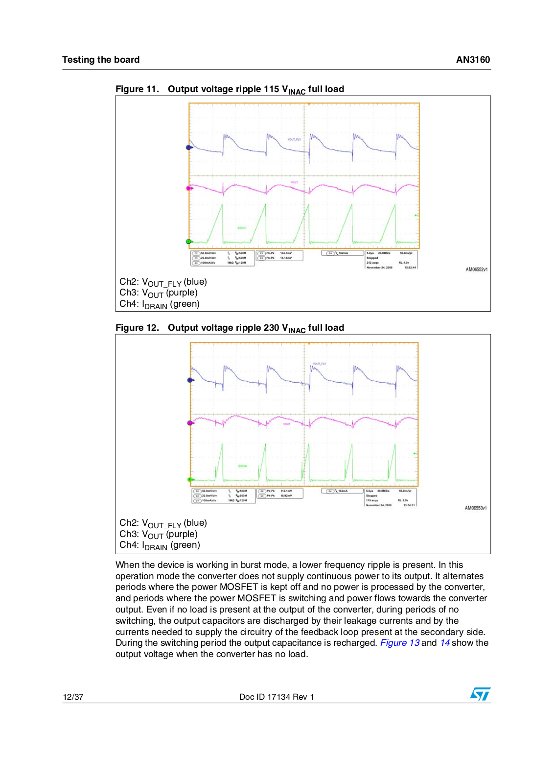
The ripple at the switching frequency superimposed at the output voltage was also measured. The board is provided with an LC filter for cleaner output voltage. The high frequency voltage ripple across capacitor C9 (VOUT_FLY), which is the output capacitor of the flyback converter before the LC filter, was also measured to verify the effectiveness of the filter and for more thorough results.

Waveforms of the two voltages (VOUT and VOUT_FLY) are shown in Figure 11 and 12.

Doc ID 17134 Rev 1

11/37

Testing the board

AN3160


Figure 11. Output voltage ripple 115 VINAC full load


Ch2: VOUT_FLY (blue)

Ch3: VOUT (purple)

Ch4: IDRAIN (green)

Figure 12. Output voltage ripple 230 VINAC full load

Ch2: VOUT_FLY (blue)

Ch3: VOUT (purple)

Ch4: IDRAIN (green)

When the device is working in burst mode, a lower frequency ripple is present. In this operation mode the converter does not supply continuous power to its output. It alternates periods where the power MOSFET is kept off and no power is processed by the converter, and periods where the power MOSFET is switching and power flows towards the converter output. Even if no load is present at the output of the converter, during periods of no switching, the output capacitors are discharged by their leakage currents and by the currents needed to supply the circuitry of the feedback loop present at the secondary side. During the switching period the output capacitance is recharged. Figure 13 and 14 show the output voltage when the converter has no load.

12/37

Doc ID 17134 Rev 1

Loading...
+ 25 hidden pages