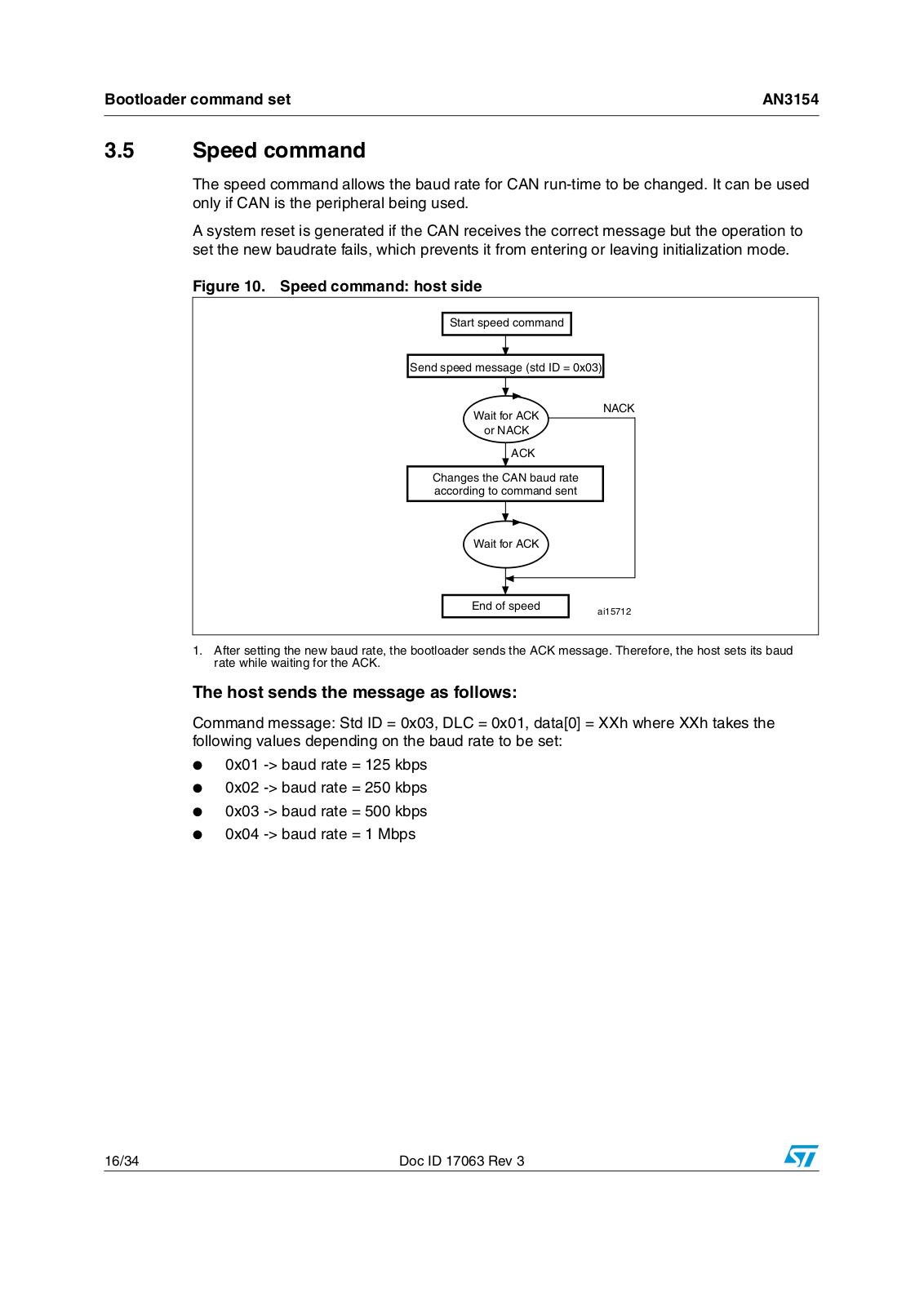
ST AN3154 Application note

AN3154

Application note

CAN protocol used in the STM32™ bootloader

Introduction

This application note describes the CAN protocol used in the STM32 microcontroller bootloader. It details each supported command. For more information about the CAN hardware resources and requirements for your device bootloader, please refer to the “STM32 system memory boot mode” application note (AN2606).

Related documents

Available from www.st.com:

AN2606 “STM32 system memory boot mode”

April 2011

Doc ID 17063 Rev 3

1/34

www.st.com

Contents

AN3154


Contents

1

Bootloader code sequence . . . . . . . . . . . . . . . . . . . . . . . . . . . . . . . . . .

. 5

2

CAN settings . . . . . . . . . . . . . . . . . . . . . . . . . . . . . . . . . . . . . . . . . . . . . . .

7

3

Bootloader command set . . . . . . . . . . . . . . . . . . . . . . . . . . . . . . . . . . . . .

8


3.1

Device-dependent bootloader parameters . . . . . . . . . . . . . . . . . . . . . . . . .

9


3.2

Get command . . . . . . . . . . . . . . . . . . . . . . . . . . . . . . . . . . . . . . . . . . . . . . .

9


3.3

Get Version & Read Protection Status command . . . . . . . . . . . . . . . . . .

12


3.4

Get ID command . . . . . . . . . . . . . . . . . . . . . . . . . . . . . . . . . . . . . . . . . . .

14


3.5

Speed command . . . . . . . . . . . . . . . . . . . . . . . . . . . . . . . . . . . . . . . . . . .

16


3.6

Read Memory command . . . . . . . . . . . . . . . . . . . . . . . . . . . . . . . . . . . . .

18


3.7

Go command . . . . . . . . . . . . . . . . . . . . . . . . . . . . . . . . . . . . . . . . . . . . . .

19


3.8

Write Memory command . . . . . . . . . . . . . . . . . . . . . . . . . . . . . . . . . . . . .

21


3.9

Erase Memory command . . . . . . . . . . . . . . . . . . . . . . . . . . . . . . . . . . . . .

24


3.10

Write Protect command . . . . . . . . . . . . . . . . . . . . . . . . . . . . . . . . . . . . . .

26


3.11

Write Unprotect command . . . . . . . . . . . . . . . . . . . . . . . . . . . . . . . . . . . .

27


3.12

Readout Protect command . . . . . . . . . . . . . . . . . . . . . . . . . . . . . . . . . . . .

29


3.13

Readout Unprotect command . . . . . . . . . . . . . . . . . . . . . . . . . . . . . . . . .

30

4

Bootloader protocol version evolution . . . . . . . . . . . . . . . . . . . . . . . . .

32

5

Revision history . . . . . . . . . . . . . . . . . . . . . . . . . . . . . . . . . . . . . . . . . . .

33

2/34

Doc ID 17063 Rev 3

AN3154

List of tables


List of tables

Table 1. CAN bootloader commands . . . . . . . . . . . . . . . . . . . . . . . . . . . . . . . . . . . . . . . . . . . . . . . . . 8 Table 2. Bootloader protocol versions . . . . . . . . . . . . . . . . . . . . . . . . . . . . . . . . . . . . . . . . . . . . . . . 32 Table 3. Document revision history . . . . . . . . . . . . . . . . . . . . . . . . . . . . . . . . . . . . . . . . . . . . . . . . . 33

Doc ID 17063 Rev 3

3/34

List of figures

AN3154


List of figures

Figure 1. Bootloader for STM32 with CAN. . . . . . . . . . . . . . . . . . . . . . . . . . . . . . . . . . . . . . . . . . . . . . 5 Figure 2. Check HSE frequency . . . . . . . . . . . . . . . . . . . . . . . . . . . . . . . . . . . . . . . . . . . . . . . . . . . . . 6 Figure 3. CAN frame . . . . . . . . . . . . . . . . . . . . . . . . . . . . . . . . . . . . . . . . . . . . . . . . . . . . . . . . . . . . . . 7 Figure 4. Get command: host side. . . . . . . . . . . . . . . . . . . . . . . . . . . . . . . . . . . . . . . . . . . . . . . . . . . 10 Figure 5. Get command: device side . . . . . . . . . . . . . . . . . . . . . . . . . . . . . . . . . . . . . . . . . . . . . . . . . 11 Figure 6. Get Version & Read Protection Status command: host side . . . . . . . . . . . . . . . . . . . . . . . 12 Figure 7. Get Version & Read Protection Status command: device side. . . . . . . . . . . . . . . . . . . . . . 13 Figure 8. Get ID command: host side . . . . . . . . . . . . . . . . . . . . . . . . . . . . . . . . . . . . . . . . . . . . . . . . 14 Figure 9. Get ID command: device side. . . . . . . . . . . . . . . . . . . . . . . . . . . . . . . . . . . . . . . . . . . . . . . 15 Figure 10. Speed command: host side . . . . . . . . . . . . . . . . . . . . . . . . . . . . . . . . . . . . . . . . . . . . . . . . 16 Figure 11. Speed command: device side. . . . . . . . . . . . . . . . . . . . . . . . . . . . . . . . . . . . . . . . . . . . . . . 17 Figure 12. Read memory command: host side . . . . . . . . . . . . . . . . . . . . . . . . . . . . . . . . . . . . . . . . . . 18 Figure 13. Read memory command: device side . . . . . . . . . . . . . . . . . . . . . . . . . . . . . . . . . . . . . . . . 19 Figure 14. Go command: host side . . . . . . . . . . . . . . . . . . . . . . . . . . . . . . . . . . . . . . . . . . . . . . . . . . . 20 Figure 15. Go command: device side . . . . . . . . . . . . . . . . . . . . . . . . . . . . . . . . . . . . . . . . . . . . . . . . . 21 Figure 16. Write Memory command: host side . . . . . . . . . . . . . . . . . . . . . . . . . . . . . . . . . . . . . . . . . . 22 Figure 17. Write memory command: device side. . . . . . . . . . . . . . . . . . . . . . . . . . . . . . . . . . . . . . . . . 23 Figure 18. Erase Memory command: host side . . . . . . . . . . . . . . . . . . . . . . . . . . . . . . . . . . . . . . . . . . 24 Figure 19. Erase Memory command: device side . . . . . . . . . . . . . . . . . . . . . . . . . . . . . . . . . . . . . . . . 25 Figure 20. Write Protect command: host side . . . . . . . . . . . . . . . . . . . . . . . . . . . . . . . . . . . . . . . . . . . 26 Figure 21. Write Protect command: device side . . . . . . . . . . . . . . . . . . . . . . . . . . . . . . . . . . . . . . . . . 27 Figure 22. Write Unprotect command: host side . . . . . . . . . . . . . . . . . . . . . . . . . . . . . . . . . . . . . . . . . 28 Figure 23. Write Unprotect command: device side . . . . . . . . . . . . . . . . . . . . . . . . . . . . . . . . . . . . . . . 28 Figure 24. Readout Protect command: host side. . . . . . . . . . . . . . . . . . . . . . . . . . . . . . . . . . . . . . . . . 29 Figure 25. Readout Protect command: device side . . . . . . . . . . . . . . . . . . . . . . . . . . . . . . . . . . . . . . . 30 Figure 26. Readout Unprotect command: host side . . . . . . . . . . . . . . . . . . . . . . . . . . . . . . . . . . . . . . 31 Figure 27. Readout Unprotect command: device side. . . . . . . . . . . . . . . . . . . . . . . . . . . . . . . . . . . . . 31

4/34

Doc ID 17063 Rev 3

AN3154

Bootloader code sequence


1 Bootloader code sequence

Figure 1.

Bootloader for STM32 with CAN


&RAMEMDETECTED


ON #!.X?2X PIN


#HECKK(3%(FREQUENCY


7AITIFOR A


COMMAND


#OMMAND


'%4%CMD


RECEIVED

'/ CMD


'%4%CMD

2$ CMD

OPTIONAL

'/ CMD


ROUTINE

ROUTINE

2OUTINES FOR

ROUTINE


LOADINGD


INTO 2!-


*0 TO?!DDRESS

AI B

1. it is recommended to send a frame with a Standard ID = 0x79.

Once the system memory boot mode is entered and the STM32 device has been configured (for more details refer to application note AN2606 “STM32 system memory boot mode”), the bootloader code waits for a frame on the CANx_Rx pin. When a detection occurs the CAN bootloader firmware starts to check the external clock frequency.

Figure 2 shows the flowchart of the frequency check.

Doc ID 17063 Rev 3

5/34

Bootloader code sequence

AN3154


Figure 2. Check HSE frequency

No HSE measurement (1)

Configure CAN baudrate at 125 Kbps Assuming that HSE = 8 MHz Initialize timeout at ~1.5 ms

Message received with stdID=0x79 and without frame error?

No

No

Decrement timeout

Timeout = 0x0 ?

Yes

Configure CAN baudrate at 125Kbps Assuming that HSE = 25MHz Initialize timeout at ~1.5 ms

Message received with stdID=0x79 and without frame error

?

No

No

Decrement timeout

Timeout = 0x0 ?

Yes

Configure CAN baudrate at 125Kbps Assuming that HSE = 14.7456MHz Initialize timeout at ~1.5 ms

Message received with stdID=0x79 and without frame error

?

No


No


Decrement timeout


Timeout = 0x0 ?


Yes


Generate System Reset

Start check HSE frequency

Yes

Yes

Yes

HSE measured with HSI and Timer (1)

Configure external Oscillator mode (System Clock = 60 MHz) Initialize timeout at ~3 ms

Yes

Message

received with stdID=0x79


and without frame error


?


No


No


Decrement timeout


Timeout=0x0?


Yes


Generate System Reset


Enter an infinite loop, waiting for any

CAN bootloader command.

ai15704c

1.For some devices, the HSE frequency is calculated using HSI oscillator connected to a timer. For other devices, this measurement is not implemented. For the devices without HSE frequency measurement, only the flow represented on the left is executed, while for the devices with HSE frequency measurement, only the flow on the right is executed. To know which flow is relative to your device, please refer to AN2606.

6/34

Doc ID 17063 Rev 3

AN3154

CAN settings


Next, the code initializes the serial interface accordingly. Using this calculated baud rate, an acknowledge byte (0x79) is returned to the host, which signals that the STM32 is ready to receive commands.

2 CAN settings

The STM32 CAN is compliant with the 2.0A and B (active) specifications with a bitrate up to 1 Mbit/s. It can receive and transmit standard frames with 11-bit identifiers as well as extended frames with 29-bit identifiers.

Figure 3 shows a CAN frame that uses the standard identifier only.

Figure 3. CAN frame


)NTER FRAMEMSPACE

)NTER FRAMEMSPACE


$ATA FRAMEM STANDARDTIDENTIFIER

OR OVERLOAD FRAME


.


!RBITRATIONIFIELD


#ONTROLTFIELD

$ATA FIELD

#2#2FIELD

!#+ FIELD


.


)$


$,#,


#2#2

%/&/

3/&/

242

)$%

R


!#+


AI

In this application, the CAN settings are:

Standard identifier (not extended)

Bitrate: at the beginning it is 125 kbps; during runtime it can be changed via the speed command to achieve a maximum bit rate of 1 Mbps.

The transmit settings (from the STM32 to the host) are:

Tx mailbox0: On

Tx mailbox1 and Tx mailbox2: Off

Tx identifier: (0x00, 0x01, 0x02, v03, 0x11, 0x21, 0x31, 0x43, 0x63, 0x73, 0x82, 0x92)

The receive settings (from the host to the STM32) are:

Synchronization byte, 0x79, is in the RX identifier and not in the data field.

RX identifier depends on the command (0x00, 0x01, 0x02, 0x03, 0x11, 0x21, 0x31, 0x43, 0x63, 0x73, 0x82, 0x92).

Error checking: If the error field (bit [6:4] in the CAN_ESR register) is different from 000b, the message is discarded and a NACK is sent to the host.

In FIFO overrun condition, the message is discarded and a NACK is sent to the host.

Incoming messages can contain from 1 to 8 data bytes.

Note:

The CAN bootloader firmware supports only one node at a time. This means that CAN


Network Management is not supported by the firmware.

Doc ID 17063 Rev 3

7/34

Bootloader command set

AN3154


3 Bootloader command set

The supported commands are listed in Table 1 below. Each command is further described in this section.

Table 1.

CAN bootloader commands


Command

Command

Command description


code


Get(1)


0x00

Gets the version and the allowed commands


supported by the current version of the bootloader


Get Version & Read Protection

0x01

Gets the bootloader version and the Read

Status(1)


Protection status of the Flash memory


Get ID(1)


0x02

Gets the chip ID

Speed


0x03

The speed command allows the baud rate for CAN


run-time to be changed.


Read Memory

0x11

Reads up to 256 bytes of memory starting from an

address specified by the application


Go


0x21

Jumps to user application code located in the


internal Flash memory or in SRAM


Write Memory

0x31

Writes up to 256 bytes to the RAM or Flash memory

starting from an address specified by the application


Erase


0x43

Erases from one to all the Flash memory sectors


Write Protect(2)

0x63

Enables the write protection for some sectors

Write Unprotect(2)

0x73

Disables the write protection for all Flash memory

sectors


Readout Protect(1)

0x82

Enables the read protection

Readout Unprotect(1)

0x92

Disables the read protection

1.Read protection – When the RDP (read protection) option is active, only this limited subset of commands is available. All other commands are NACKed and have no effect on the device. Once the RDP has been removed, the other commands become active.

2.See Section 3.1 below

Communication safety

Each packet is either accepted (ACK answer) or discarded (NACK answer):

ACK message = 0x79

NACK message = 0x1F

8/34

Doc ID 17063 Rev 3

AN3154

Bootloader command set


3.1Device-dependent bootloader parameters

While the CAN bootloader protocol’s command set and sequences are the same for all STM32 devices, some parameters are device-dependent. For a few commands, the value of some parameters may depend on the device used. The concerned parameters are listed below:

PID (product ID), which changes with the device

Valid memory addresses (RAM, Flash memory, system memory, option byte areas) accepted by the bootloader when the Read Memory, Go and Write Memory commands are executed

Size of the Flash memory sector used when executing the Write Protect command

For more details about the value of these parameters for the device you are using please refer to the “Device-dependent boot loader parameters” section in the “STM32 system memory boot mode” application note (AN2606).

3.2Get command

The Get command allows the host to get the version of the bootloader and the supported commands. When the bootloader receives the get command, it transmits the bootloader version and the supported command codes to the host.

Doc ID 17063 Rev 3

9/34

ST AN3154 Application note

Bootloader command set

AN3154


Figure 4. Get command: host side

3TARTTGETGCOMMAND


3END MESSAGE WITHSSTDG)$ H


7AITIFOR !#+

.!#+


OR .!#+


!#+


2ECEIVEE MESSAGE NUMBERBOF BYTES E


VERSION COMMANDS


2ECEIVEE MESSAGE "OOTLOADERLVERSION


2ECEIVEE MESSAGE 'ET COMMAND


2ECEIVEE MESSAGE 'ET 6ERSION


2EAD 0ROTECTIONOSTATUS COMMAND


2ECEIVEE MESSAGE 'ET )$TCOMMAND


2ECEIVEE MESSAGE 3PEED COMMAND


2ECEIVEE MESSAGE 2EADECOMMAND


2ECEIVEE MESSAGE 'O'COMMAND


2ECEIVEE MESSAGE 7RITETMEMORYYCOMMAND


2ECEIVEE MESSAGE %RASESMEMORYYCOMMAND


2ECEIVEE MESSAGE 7RITET0ROTECTRCOMMAND


2ECEIVEE MESSAGE 7RITET5NPROTECTPCOMMAND


2ECEIVEE MESSAGE 2EADOUT 0ROTECT COMMAND


2ECEIVEE MESSAGE 2EADOUT 5NPROTECT COMMAND


7AITIFOR !#+


OR .!#+


%NDNOF GET COMMAND


AI


10/34

Doc ID 17063 Rev 3

AN3154

Bootloader command set


The host sends messages as follows:

Command message: Std ID = 0x00, data length code (DLC) = ‘not important’.

Figure 5. Get command: device side

3TARTTGETGCOMMAND


2ECEIVED MESSAGE

.O


WITH )$H X


9ES


3END !#+ MESSAGE

3END .!#+ MESSAGE

3END MESSAGE .UMBERMOF BYTES E

VERSION COMMANDS

3END MESSAGE "OOTLOADERLVERSION

3END DMESSAGES 3UPPORTEDECOMMANDS

3END !#+ MESSAGE

%NDNOF GET COMMAND

AI

The STM32 sends messages as follows:

Message 1:

Std ID = 0x00, DLC = 1, data = 0x79

- ACK

Message 2:

Std ID = 0x00, DLC = 1 data = N = 12 = the number of bytes to be sent -1


(1 N +1 256)


Message 3:

Std ID = 0x00, DLC = 1, data = bootloader version (0 < version 255)

Message 4:

Std ID = 0x00, DLC = 1, data = 0x00

- Get command

Message 5:

Std ID = 0x00, DLC = 1, data = 0x01

- Get Version & Read Protection


Status command

Message 6:

Std ID = 0x00, DLC = 1, data = 0x02

- Get ID command

Message 7:

Std ID = 0x00, DLC = 1, data = 0x03

- Speed command

Message 8:

Std ID = 0x00, DLC = 1, data = 0x11

- Read memory command

Message 9:

Std ID = 0x00, DLC = 1, data = 0x21

- Go command

Message 10:

Std ID = 0x00, DLC = 1, data = 0x31

- Write memory command

Message 11:

Std ID = 0x00, DLC = 1, data = 0x43

- Erase memory command

Doc ID 17063 Rev 3

11/34

Loading...
+ 23 hidden pages