


AN3141
Application note
LC filters for mobile phone LCD and camera links
Introduction
The mobile phone is a compact, small device, which radiates high power, and needs to have
a very good sensitivity for signal reception. This functional conflict generates an EMI issue,
which can be addressed by filtering.
September 2010 Doc ID 17004 Rev 1 1/14
www.st.com
EMI issue on the mobile phone AN3141
1 EMI issue on the mobile phone
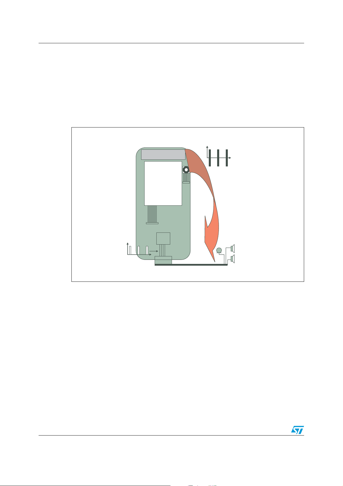
The baseband part of the mobile phone can be either the object or the source of EMI.
A mobile phone can generate a power up to 2 W in the GSM band. This radiation can impact
external wires, such as the hands-free kit, or USB cable. This can generate TDMA noise on
the audio part, but also errors on the USB link. In this case the mobile phone is the object of
EMI, as shown on Figure 1.
Figure 1. Baseband is a victim of EMI
Antenna radiation, TDMA
Antenna radiation, TDMA
Antenna
Antenna
Antenna
t
t
LCD
LCD
LCD
Camera
Camera
Camera
Flex
Flex
Flex
BB
BB
BB
t
TDMA
TDMA
demodulation
demodulation
t
The mobile phone can be also a source of EMI, regarding the RF part.
The sensitivity of a mobile phone needs to be very good, especially concerning
communications far from the base station. According to TS125101 and TS100910
standards, sensitivity must be as low as -104 dBm in GSM mode and -107 dBm in
W-CDMA. These sensitivities can be achieved by a radio system, but it needs to be free of
external noise.
As the digital signal spectrum is wide-band, harmonics can occur at the same frequency as
the receiving frequency. Radiation at these frequencies, by a flex for example, can impact
the antenna, producing noise at the LNA input.
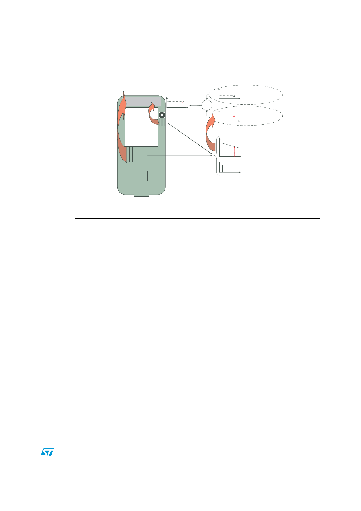
Figure 2 presents a case where the base station (BST) signal received by the antenna is
lower than the flex radiation. The base station signal is below the noise floor, and cannot be
used by the mobile phone. Only a BST signal higher than noise floor can be received.
Mobile phone sensitivity is thus defined by the flex radiation noise, and not by the RF system
performance.
2/14 Doc ID 17004 Rev 1
AN3141 EMI issue on the mobile phone
Figure 2. Baseband is a source of EMI, which reduces the mobile’s sensitivity
Only flex radiation,
BST signal is canceled
Antenna
Antenna
Camera
Camera
Flex
LCD
LCD
Flex radiation
Flex
Flex
BB
BB
f
+
Flex
radiation
Coming from BST
GSM
f
Coming from Flex radiation
f
Flex signal,
frequency domain
f
Flex signal,
temporal domain
t
To keep the mobile phone sensitivity at the radio level, the radiated digital signal needs to be
filtered.
Doc ID 17004 Rev 1 3/14
Link between baseband processor and LCD or camera AN3141
2 Link between baseband processor and LCD or
camera
One of the noisy digital links is the LCD or camera bus. The trends for LCD size and camera
resolution are both increasing, thus requiring the transmission of greater and greater
volumes of data. These trends result in clock frequencies which are now in the range of 1050 MHz. Harmonics are at the same frequencies as the GSM reception band. Baseband
processor are also getting faster and faster, inducing very low rise and fall times, making the
digital signal spectrum wide band.
In a mobile phone, these links use a Flex PCB several centimeters long, which acts as an
antenna.
Consequently, combining all these parameters, digital links can drastically reduce the
sensitivity of a mobile phone.
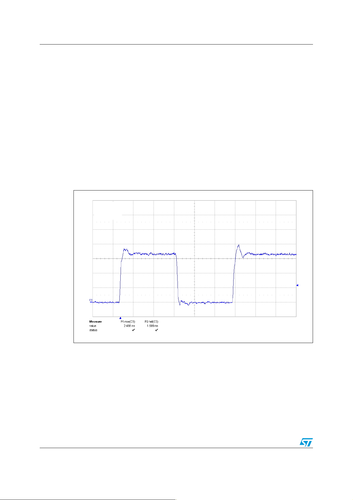
Figure 3 shows the signal waveform measured on an LCD link.
Figure 3. Signal to control the LCD
1 V/div
20 ns/div
This signal has rise and fall time in the range of 2 ns. These edges will radiate
electromagnetic fields in the in the range of RX mobile phone frequencies.
To evaluate the spectrum generated by this waveform, a measurement has been done on
the similar signal, with a spectrum analyzer:
● Signal amplitude: 3 V
● Signal frequency: 20 MHz
● Modulation: PRBS 2n-1
● Rise and fall time: 1.8 ns
4/14 Doc ID 17004 Rev 1
AN3141 Link between baseband processor and LCD or camera
We choose to perform a measurement at 940 MHz, which is near the middle of the GSM RX
band.
The measurement setup is presented in Figure 4. Due to the spectrum content of a digital
signal, band-pass filter is needed to avoid saturation of the spectrum analyzer input stage.
Figure 4. Harmonic measurement test setup
Spectrum analyzer
Cavity band-
pass filter
Signal generator
50 Ω output
Isolator
DUT
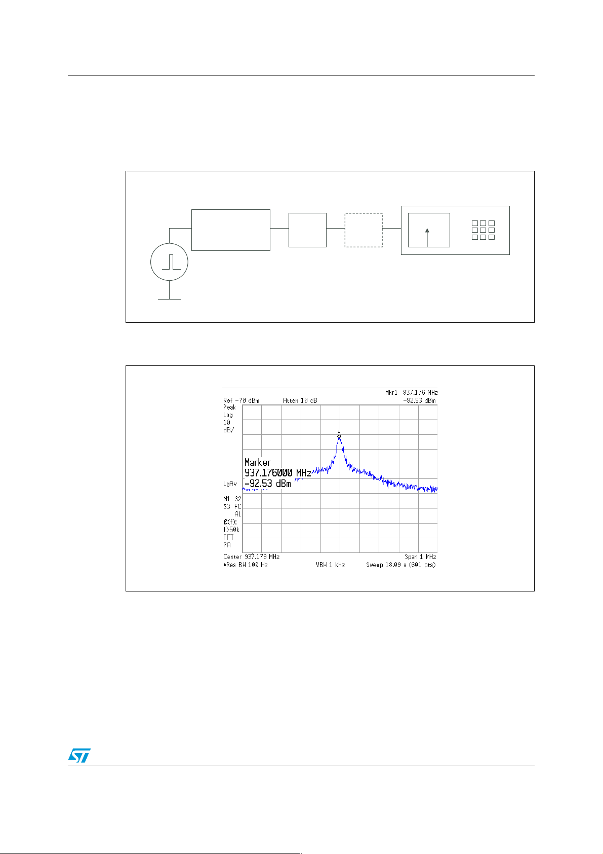
Measurement results is shown in Figure 5 (DUT short-circuited).
Figure 5. Spectrum at 940 MHz of a 1.8 ns rise/fall time, 20 MHz signal
The result shows that the emission of this signal is significant regarding the required
sensitivity of a mobile phone.
This measurement was performed on one line, while digital links integrate several lines in
parallel. In addition, measurements have been performed on 50 environment, which is not
the case in the application (link is not impedance matched, drivers are low impedance and
receiver high impedance). Consequently, radiated field can be very high.
Without any filtering, this signal can drastically decrease the sensitivity of a mobile phone.
Doc ID 17004 Rev 1 5/14

Filtering the LCD or camera link AN3141
3 Filtering the LCD or camera link
The filter choice is made according two parameters:
● Bandwidth, to keep the signal integrity in case of digital signals
● Rejection at the frequency to attenuate, i.e. at RX frequencies of mobile phone
LCD and camera link clock frequency is in the range of 10 - 50 MHz, and the digital signal is
a wide band spectrum signal. Consequently, bandwidth of the filter needs to be in the range
of 200 MHz to keep good signal integrity.
As shown before (see Figure 2), the filter must reject the mobile phone reception
frequencies: GSM to W-CDMA gives frequencies from 869 MHz to 2.17 GHz.
In this frequency range attenuation needs to be as high as possible to limit the emissions of
the digital link.
Three types of device have been developed by STMicroelectronics to ensure good signal
integrity:
● EMIF10-LCD02F3, 10-line version, (or EMIF07-LCD02F3, 7-line version)
● EMIF08-LCD04M16,
● EMIF10-LCD03F3 (or EMIF07-LCD03F3)
These devices offer a bandwidth of 200 MHz, as shown in Figure 6, Figure 7 and Figure 8.
Attenuation at RX frequencies are not the same:
● EMIFxx-LCD02F3 is an RC type filter and provides attenuation of -25 dB at 900 MHz.
● EMIF08-LCD04M16 is an LC filter and provides attenuation of -35 dB at least on RX
band, which is better than the RC type filter.
● EMIFxx-LCD03F3 is an LC type filter and provides attenuation of -50 dB on RX band -
better than the RC type filter.
6/14 Doc ID 17004 Rev 1

AN3141 Filtering the LCD or camera link
Figure 6. Frequency response of EMIF10-LCD02F3, RC type
dB
0
-10
-20
-30
-40
-50
F (Hz)
-60
100k 1M 10M 100M 1G
Line 1
Line 3 Line 4
Line 5 Line 6
Line 7 Line 8
Line 2
6G
Figure 7. Frequency response of EMIF08-LCD04M16, LC type
dB
0
-5
-10
-15
-20
-25
-30
-35
-40
-45
-50
-55
-60
-65
-70
I2-O2 #1
-
I3 O3 #1
-
I4
O4 #1
-
I5
O5 #1
-
I6
O6 #1
-
I7
O7 #1
-
I8
O8 #1
100k 1M 10M 100M 1G
F (Hz)
Doc ID 17004 Rev 1 7/14

Filtering the LCD or camera link AN3141
Figure 8. Frequency response of EMIF10-LCD03F3, LC type
dB
0
-10
-20
-30
-40
-50
-60
-70
-80
F (Hz)
-90
100k 1M 10M 100M 1G
Line 1
Line 3
Line 5
Line 7
Line 2
Line 4
Line 6
Line 8
6G
All filters have a high bandwidth so they have a very small impact on the signal in the time
domain, as shown on the Figure 9.
Figure 9. Frequency response of EMIF10-LCD03F3, LC type
Without filter
With RC type,
EMIF10 -LCD02F3
With LC type,
EMIF08 -LCD04M16
With LC type,
EMIF10 -LCD03F3
1 V/div.
10 ns/div.
8/14 Doc ID 17004 Rev 1

AN3141 Filtering the LCD or camera link
The same measurements have been performed in the frequency domain, at 940 MHz.
Figure 10, Figure 11, and Figure 12 show the harmonic power with RC and LC type filter.
Figure 10. Spectrum at 940 MHz, with RC type filter, EMIF10-LCD02F3
Figure 11. Spectrum at 940 MHz, with LC type filter, EMIF08-LCD04M16
Doc ID 17004 Rev 1 9/14

Filtering the LCD or camera link AN3141
Figure 12. Spectrum at 940 MHz, with LC type filter, EMIF10-LCD03F3
Power at 940 MHz, without filter was -92.5 dBm (see Figure 5):
● With EMIF10-LCD02F3, RC type filter, the power is decreased to -120 dBm.
● With EMIF08-LCD04M16, LC type filter, the power is decreased to -126 dBm.
● With EMIF10-LCD03F3, LC type filter, the power becomes insignificant, as it is lower
than the -130 dBm, which is the noise floor of the measurement system.
This shows that the use of a filter decreased the harmonic levels of the LCD and camera
links.
An LC type filter, such as the EMIF08-LCD04M16 or EMIF10-LCD03F3, ensures the best
filtering, because harmonic power is insignificant, while maintaining good signal integrity.
10/14 Doc ID 17004 Rev 1

AN3141 Filter placement
4 Filter placement
The goal of filters is to avoid flex radiation at mobile phone reception frequencies.
Consequently, filters need to be placed just before the flex connector, at the digital signal
generator side.
For implementation on the LCD link, filters should be placed on the main PCB, between
baseband processor and the flex connector. By contrast, for the camera link, filters will be
placed on the camera PCB, as the signal comes from the camera to go to the baseband
processor. In case of a bidirectional link, both sides of the flex need to be filtered.
Figure 13 show filter placement for LCD and camera links.
Figure 13. Filters placement on LCD and camera links
Antenna
Antenna
Camera
LCD
LCD
Flex
Flex
BB
BB
Filters placement
Doc ID 17004 Rev 1 11/14

Conclusion AN3141
5 Conclusion
Mobile phone LCD or camera links can radiate on the RX frequencies, which can impact
mobile phone sensitivity.
To evaluate this radiation, a spectrum measurement has been performed at RX GSM
frequencies, on a digital signal having 1.8 ns rise and fall time. The measurement identifies
a power of -92 dBm at 940 MHz, on a single line, and 50 Ω environment. This is huge
regarding the requested sensitivity on GSM band.
To reduce this noise, filtering is needed. It must respect the signal integrity, and filter RX
band frequencies.
EMIF08-LCD04M16, EMIFxx-LCD02F3 and EMIFxx-LCD03F3 have been designed to filter
parallel LCD and camera links, while fully respecting signal integrity. Time domain
measurement shows a very low impact on the signal.
Frequency domain measurements with filters show attenuation at RX band frequencies:
● From -92 dBm without filter to -120 dBm with EMIF10-LCD02F3, RC type filter, at
F=940 MHz
● From -92 dBm without filter to -126 dBm with EMIF08-LCD04M16, LC type filter, at
F=940 MHz
● From -92 dBm without filter to a power lower than -130 dBm with EMIF10-LCD03F3, LC
type filter, at F=940 MHz
Consequently, using filters, before the flex connection, reduces the emission of the flex at
RX frequencies.
Using LC type filters:
● Does not impact the signal integrity
● Decreased the reception frequency range power to an insignificant value
Consequently, the RF system sensitivity is not affected. It remains at its own value.
12/14 Doc ID 17004 Rev 1

AN3141 Revision history
6 Revision history
Table 1. Document revision history
Date Revision Changes
16-Sep-2010 1 Initial release.
Doc ID 17004 Rev 1 13/14

AN3141
Please Read Carefully:
Information in this document is provided solely in connection with ST products. STMicroelectronics NV and its subsidiaries (“ST”) reserve the
right to make changes, corrections, modifications or improvements, to this document, and the products and services described herein at any
time, without notice.
All ST products are sold pursuant to ST’s terms and conditions of sale.
Purchasers are solely responsible for the choice, selection and use of the ST products and services described herein, and ST assumes no
liability whatsoever relating to the choice, selection or use of the ST products and services described herein.
No license, express or implied, by estoppel or otherwise, to any intellectual property rights is granted under this document. If any part of this
document refers to any third party products or services it shall not be deemed a license grant by ST for the use of such third party products
or services, or any intellectual property contained therein or considered as a warranty covering the use in any manner whatsoever of such
third party products or services or any intellectual property contained therein.
UNLESS OTHERWISE SET FORTH IN ST’S TERMS AND CONDITIONS OF SALE ST DISCLAIMS ANY EXPRESS OR IMPLIED
WARRANTY WITH RESPECT TO THE USE AND/OR SALE OF ST PRODUCTS INCLUDING WITHOUT LIMITATION IMPLIED
WARRANTIES OF MERCHANTABILITY, FITNESS FOR A PARTICULAR PURPOSE (AND THEIR EQUIVALENTS UNDER THE LAWS
OF ANY JURISDICTION), OR INFRINGEMENT OF ANY PATENT, COPYRIGHT OR OTHER INTELLECTUAL PROPERTY RIGHT.
UNLESS EXPRESSLY APPROVED IN WRITING BY AN AUTHORIZED ST REPRESENTATIVE, ST PRODUCTS ARE NOT
RECOMMENDED, AUTHORIZED OR WARRANTED FOR USE IN MILITARY, AIR CRAFT, SPACE, LIFE SAVING, OR LIFE SUSTAINING
APPLICATIONS, NOR IN PRODUCTS OR SYSTEMS WHERE FAILURE OR MALFUNCTION MAY RESULT IN PERSONAL INJURY,
DEATH, OR SEVERE PROPERTY OR ENVIRONMENTAL DAMAGE. ST PRODUCTS WHICH ARE NOT SPECIFIED AS "AUTOMOTIVE
GRADE" MAY ONLY BE USED IN AUTOMOTIVE APPLICATIONS AT USER’S OWN RISK.
Resale of ST products with provisions different from the statements and/or technical features set forth in this document shall immediately void
any warranty granted by ST for the ST product or service described herein and shall not create or extend in any manner whatsoever, any
liability of ST.
ST and the ST logo are trademarks or registered trademarks of ST in various countries.
Information in this document supersedes and replaces all information previously supplied.
The ST logo is a registered trademark of STMicroelectronics. All other names are the property of their respective owners.
© 2010 STMicroelectronics - All rights reserved
STMicroelectronics group of companies
Australia - Belgium - Brazil - Canada - China - Czech Republic - Finland - France - Germany - Hong Kong - India - Israel - Italy - Japan -
Malaysia - Malta - Morocco - Philippines - Singapore - Spain - Sweden - Switzerland - United Kingdom - United States of America
www.st.com
14/14 Doc ID 17004 Rev 1
 Loading...