ST AN3133 Application note

AN3133

Application note

Using the STM8L15x/STM8L16x real time clock


Introduction


A real-time clock (RTC) is a computer clock that keeps track of the current time. Although


RTCs are often used in personal computers, servers and embedded systems, they are also


present in almost any electronic device that requires accurate time keeping. Microcontrollers


supporting RTC can be used for chronometers, alarm clocks, watches, small electronic


agendas, and many other devices.


This application note describes the features of the real-time clock (RTC) controller


embedded in medium density STM8L15x and medium+ and high density STM8L15x/16x


devices microcontrollers, together with the steps required to configure the RTC for use with


the calendar, alarm, periodic wakeup unit, tamper detection and chronometer.


Five applicative examples are provided with useful configuration information to allow the


user to quickly and correctly configure the RTC for calendar, alarm, periodic wakeup unit,


tamper detection and chronometer applications.

Note:

All examples and explanations are based on the STM8L15x/16x firmware library. Please


refer to the STM8L15x and STM8L16x microcontroller family reference manual (RM0031)


for more details.

June 2011

Doc ID 16956 Rev 3

1/43

www.st.com

Contents

AN3133


Contents

1

Real-time clock overview . . . . . . . . . . . . . . . . . . . . . . . . . . . . . . . . . . . .

. 6


1.1

RTC calendar . . . . . . . . . . . . . . . . . . . . . . . . . . . . . . . . . . . . . . . . . . . . . . .

6


1.1.1

Sub-seconds . . . . . . . . . . . . . . . . . . . . . . . . . . . . . . . . . . . . . . . . . . . . .

. 7


1.1.2

Fine RTC calendar adjustments . . . . . . . . . . . . . . . . . . . . . . . . . . . . . .

. 7


1.2

RTC alarm . . . . . . . . . . . . . . . . . . . . . . . . . . . . . . . . . . . . . . . . . . . . . . . . .

8


1.3

RTC periodic wakeup unit . . . . . . . . . . . . . . . . . . . . . . . . . . . . . . . . . . . . .

9


1.4

RTC smooth digital calibration . . . . . . . . . . . . . . . . . . . . . . . . . . . . . . . . . .

9


1.5

RTC tamper detection . . . . . . . . . . . . . . . . . . . . . . . . . . . . . . . . . . . . . . .

10


1.6

RTC and low-power consumption . . . . . . . . . . . . . . . . . . . . . . . . . . . . . .

12


1.7

Signals generated by RTC . . . . . . . . . . . . . . . . . . . . . . . . . . . . . . . . . . . .

13


1.7.1

RTC_CALIB output . . . . . . . . . . . . . . . . . . . . . . . . . . . . . . . . . . . . . . . .

13


1.7.2

RTC_ALARM output . . . . . . . . . . . . . . . . . . . . . . . . . . . . . . . . . . . . . . .

14

1.8 RTC security aspects . . . . . . . . . . . . . . . . . . . . . . . . . . . . . . . . . . . . . . . . 15

1.8.1 RTC Register write protection . . . . . . . . . . . . . . . . . . . . . . . . . . . . . . . . 15 1.8.2 Enter/Exit initialization mode . . . . . . . . . . . . . . . . . . . . . . . . . . . . . . . . . 15 1.8.3 Synchronization . . . . . . . . . . . . . . . . . . . . . . . . . . . . . . . . . . . . . . . . . . . 16

2

Programming the RTC . . . . . . . . . . . . . . . . . . . . . . . . . . . . . . . . . . . . . .

17


2.1

Initializing the calendar . . . . . . . . . . . . . . . . . . . . . . . . . . . . . . . . . . . . . . .

17


2.2

Programming the alarm . . . . . . . . . . . . . . . . . . . . . . . . . . . . . . . . . . . . . .

17


2.3

Programming the Auto-wakeup unit . . . . . . . . . . . . . . . . . . . . . . . . . . . . .

18

3

Useful RTC configuration examples . . . . . . . . . . . . . . . . . . . . . . . . .

. . 19


3.1

Delivering a 1-Hz signal to the calendar using different clock sources

. . 19


3.2

Configuring the alarm behavior using the MSKx bits . . . . . . . . . . . . . .

. . 20


3.3

Maximum and minimum RTC_CALIB output frequency . . . . . . . . . . . . .

. 21


3.4

Maximum and minimum RTC wakeup period . . . . . . . . . . . . . . . . . . . . .

. 21


3.4.1 Periodic timebase/wakeup clock configuration 1 . . . . . . . . . . . . . . . .

. . 22


3.4.2 Periodic timebase/wake up clock configuration 2 . . . . . . . . . . . . . . .

. . 22


3.4.3 Periodic timebase/wakeup clock configuration 3 . . . . . . . . . . . . . . . .

. . 24


3.4.4 Summary of timebase/wakeup period extrema . . . . . . . . . . . . . . . . .

. . 24

4

RTC features summary . . . . . . . . . . . . . . . . . . . . . . . . . . . . . . . . . . . . .

. 25

2/43

Doc ID 16956 Rev 3

AN3133 Contents

5

RTC firmware API . . . . . . . . . . . . . . . . . . . . . . . . . . . . . . . . . . . . . . . . . .

26


5.1

Function groups . . . . . . . . . . . . . . . . . . . . . . . . . . . . . . . . . . . . . . . . . . . .

26

6

Application examples . . . . . . . . . . . . . . . . . . . . . . . . . . . . . . . . . . . . . . .

29


6.1

Example 1: Calendar and alarm . . . . . . . . . . . . . . . . . . . . . . . . . . . . . . . .

29


6.2

Example 2: Wakeup from low power mode . . . . . . . . . . . . . . . . . . . . . . .

31


6.3

Example 3: Periodic event generation using the wakeup unit . . . . . . . . .

32


6.4

Example 4: Tamper detection . . . . . . . . . . . . . . . . . . . . . . . . . . . . . . . . . .

32


6.5

Example 5: Chronometer . . . . . . . . . . . . . . . . . . . . . . . . . . . . . . . . . . . . .

37

7

Revision history . . . . . . . . . . . . . . . . . . . . . . . . . . . . . . . . . . . . . . . . . . .

42

Doc ID 16956 Rev 3

3/43

List of tables

AN3133


List of tables

Table 1. Calibration window description . . . . . . . . . . . . . . . . . . . . . . . . . . . . . . . . . . . . . . . . . . . . . . 10 Table 2. Low power modes where RTC is actor. . . . . . . . . . . . . . . . . . . . . . . . . . . . . . . . . . . . . . . . 13 Table 3. Steps to initialize the calendar . . . . . . . . . . . . . . . . . . . . . . . . . . . . . . . . . . . . . . . . . . . . . . 17 Table 4. Steps to configure the alarm. . . . . . . . . . . . . . . . . . . . . . . . . . . . . . . . . . . . . . . . . . . . . . . . 17 Table 5. Steps to configure the Auto wake-up unit . . . . . . . . . . . . . . . . . . . . . . . . . . . . . . . . . . . . . . 18 Table 6. Calendar clock equal to 1Hz with different clock sources. . . . . . . . . . . . . . . . . . . . . . . . . . 19 Table 7. Alarm combination . . . . . . . . . . . . . . . . . . . . . . . . . . . . . . . . . . . . . . . . . . . . . . . . . . . . . . . 20 Table 8. Mask configurations for setting an alarm every 125 ms (for RTCCLK = 32.768kHz) . . . . . 21 Table 9. RTC_CALIB output frequency versus clock source . . . . . . . . . . . . . . . . . . . . . . . . . . . . . . 21 Table 10. Timebase/wakeup unit period resolution with clock configuration 1 . . . . . . . . . . . . . . . . . . 22 Table 11. Timebase/wakeup unit period resolution with clock configuration 2 . . . . . . . . . . . . . . . . . . 23 Table 12. Timebase/wakeup unit period resolution with clock configuration 2 . . . . . . . . . . . . . . . . . . 23 Table 13. Min. and max. timebase/wakeup period (medium density products) . . . . . . . . . . . . . . . . . 24 Table 14. Min. and max. timebase/wakeup period (med+ and high-density products). . . . . . . . . . . . 24 Table 15. Summary of RTC features by product family . . . . . . . . . . . . . . . . . . . . . . . . . . . . . . . . . . . 25 Table 16. RTC function groups. . . . . . . . . . . . . . . . . . . . . . . . . . . . . . . . . . . . . . . . . . . . . . . . . . . . . . 26 Table 17. Buttons and corresponding actions . . . . . . . . . . . . . . . . . . . . . . . . . . . . . . . . . . . . . . . . . . 33 Table 18. Buttons and corresponding actions . . . . . . . . . . . . . . . . . . . . . . . . . . . . . . . . . . . . . . . . . . 37 Table 19. Document revision history . . . . . . . . . . . . . . . . . . . . . . . . . . . . . . . . . . . . . . . . . . . . . . . . . 42

4/43

Doc ID 16956 Rev 3

AN3133

List of figures


List of figures

Figure 1.

STM8L15x/16x RTC calendar fields . . . . . . . . . . . . . . . . . . . . . . . . . . . . . . . . . . . . . . . . . .

. 6

Figure 2.

Example of calendar display on an LCD. . . . . . . . . . . . . . . . . . . . . . . . . . . . . . . . . . . . . . .

. 7

Figure 3.

RTC alarm fields . . . . . . . . . . . . . . . . . . . . . . . . . . . . . . . . . . . . . . . . . . . . . . . . . . . . . . . . .

. 8

Figure 4.

Typical crystal accuracy plotted against temperature (and different values of K) . . . . . . .

. 9

Figure 5.

Example of tamper detection circuit . . . . . . . . . . . . . . . . . . . . . . . . . . . . . . . . . . . . . . . . . .

11

Figure 6.

Tamper sampling with pre-charge pulse. . . . . . . . . . . . . . . . . . . . . . . . . . . . . . . . . . . . . . .

11

Figure 7.

Example of tamper filtering . . . . . . . . . . . . . . . . . . . . . . . . . . . . . . . . . . . . . . . . . . . . . . . . .

12

Figure 8.

RTC_CALIB clock sources . . . . . . . . . . . . . . . . . . . . . . . . . . . . . . . . . . . . . . . . . . . . . . . . .

14

Figure 9.

Alarm flag routed to RTC_ALARM output. . . . . . . . . . . . . . . . . . . . . . . . . . . . . . . . . . . . . .

14

Figure 10.

Periodic wake-up routed to RTC_ALARM pinout . . . . . . . . . . . . . . . . . . . . . . . . . . . . . . . .

15

Figure 11.

Prescalers from RTC clock source to calendar unit . . . . . . . . . . . . . . . . . . . . . . . . . . . . . .

19

Figure 12.

Prescalers connected to the timebase/wakeup unit for configuration 1 . . . . . . . . . . . . . . .

22

Figure 13.

Prescalers connected to the wake up unit for configurations 2 and 3 . . . . . . . . . . . . . . . .

22

Figure 14.

Calendar example: main program flowchart . . . . . . . . . . . . . . . . . . . . . . . . . . . . . . . . . . . .

30

Figure 15.

Calendar example: RTC alarm ISR flowchart. . . . . . . . . . . . . . . . . . . . . . . . . . . . . . . . . . .

30

Figure 16.

Wakeup from low power mode example: main program flowchart . . . . . . . . . . . . . . . . . . .

31

Figure 17.

Wakeup from low power mode example: RTC ISR flowchart . . . . . . . . . . . . . . . . . . . . . . .

32

Figure 18.

LCD display description . . . . . . . . . . . . . . . . . . . . . . . . . . . . . . . . . . . . . . . . . . . . . . . . . . .

33

Figure 19.

Main program flowchart . . . . . . . . . . . . . . . . . . . . . . . . . . . . . . . . . . . . . . . . . . . . . . . . . . .

34

Figure 20.

RTC Tamper ISR flowchart . . . . . . . . . . . . . . . . . . . . . . . . . . . . . . . . . . . . . . . . . . . . . . . .

35

Figure 21.

EXTI ISR flowchart for UP button . . . . . . . . . . . . . . . . . . . . . . . . . . . . . . . . . . . . . . . . . . .

35

Figure 22.

EXTI ISR flowchart for DOWN button . . . . . . . . . . . . . . . . . . . . . . . . . . . . . . . . . . . . . . . .

36

Figure 23.

EXTI ISR flowchart for KEY button . . . . . . . . . . . . . . . . . . . . . . . . . . . . . . . . . . . . . . . . . .

36

Figure 24.

Main program flowchart . . . . . . . . . . . . . . . . . . . . . . . . . . . . . . . . . . . . . . . . . . . . . . . . . . .

38

Figure 25.

RTC Tamper ISR flowchart . . . . . . . . . . . . . . . . . . . . . . . . . . . . . . . . . . . . . . . . . . . . . . . .

39

Figure 26.

EXTI ISR flowchart for DOWN button . . . . . . . . . . . . . . . . . . . . . . . . . . . . . . . . . . . . . . . .

39

Figure 27.

EXTI ISR flowchart for SEL button . . . . . . . . . . . . . . . . . . . . . . . . . . . . . . . . . . . . . . . . . .

40

Figure 28.

EXTI ISR flowchart for KEY button . . . . . . . . . . . . . . . . . . . . . . . . . . . . . . . . . . . . . . . . . .

41

Doc ID 16956 Rev 3

5/43

Real-time clock overview

AN3133


1 Real-time clock overview

The real-time clock (RTC) embedded in STM8L15x and STM8L16x microcontrollers can be used to provide a full-featured calendar, alarm and periodic wakeup unit.

Additional features are available on medium+ and high density devices, such as calendar synchronization, digital calibration and advanced tamper detection.

Refer to Section 4: RTC features summary for the complete list of features available on medium, medium+ and high density devices.

1.1RTC calendar

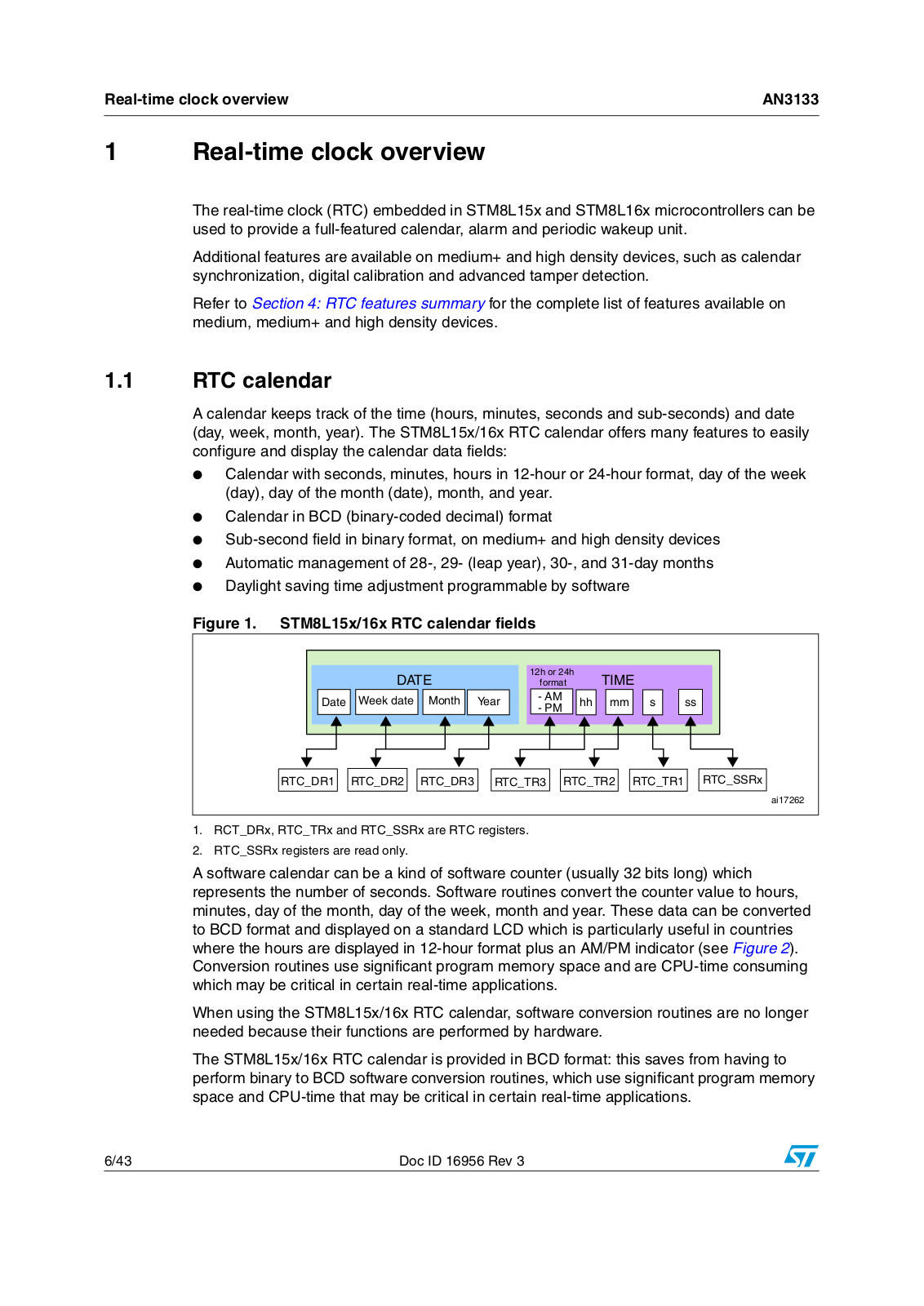
A calendar keeps track of the time (hours, minutes, seconds and sub-seconds) and date (day, week, month, year). The STM8L15x/16x RTC calendar offers many features to easily configure and display the calendar data fields:

Calendar with seconds, minutes, hours in 12-hour or 24-hour format, day of the week (day), day of the month (date), month, and year.

Calendar in BCD (binary-coded decimal) format

Sub-second field in binary format, on medium+ and high density devices

Automatic management of 28-, 29- (leap year), 30-, and 31-day months

Daylight saving time adjustment programmable by software

Figure 1. STM8L15x/16x RTC calendar fields


$!4%


H OR H


4)-%


FORMAT


$ATE

7EEKEDATE

-ONTH

9EAR

!-


HH

MM

S

SS

0-


24#?$2

24#?$2

24#?$2

24#?42

24#?42

24#?42

24#?332X


AI

1.RCT_DRx, RTC_TRx and RTC_SSRx are RTC registers.

2.RTC_SSRx registers are read only.

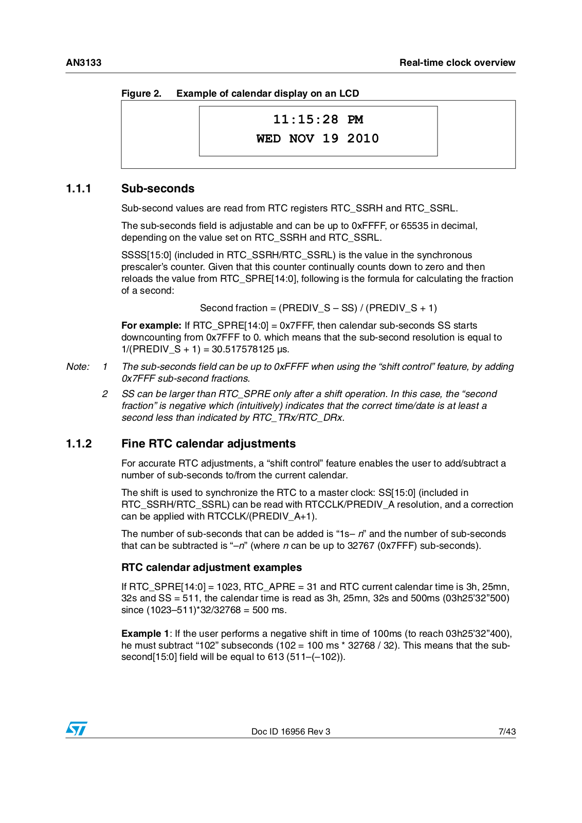
A software calendar can be a kind of software counter (usually 32 bits long) which represents the number of seconds. Software routines convert the counter value to hours, minutes, day of the month, day of the week, month and year. These data can be converted to BCD format and displayed on a standard LCD which is particularly useful in countries where the hours are displayed in 12-hour format plus an AM/PM indicator (see Figure 2). Conversion routines use significant program memory space and are CPU-time consuming which may be critical in certain real-time applications.

When using the STM8L15x/16x RTC calendar, software conversion routines are no longer needed because their functions are performed by hardware.

The STM8L15x/16x RTC calendar is provided in BCD format: this saves from having to perform binary to BCD software conversion routines, which use significant program memory space and CPU-time that may be critical in certain real-time applications.

6/43

Doc ID 16956 Rev 3

AN3133

Real-time clock overview


Figure 2. Example of calendar display on an LCD

11:15:28 PM

WED NOV 19 2010

1.1.1Sub-seconds

Sub-second values are read from RTC registers RTC_SSRH and RTC_SSRL.

The sub-seconds field is adjustable and can be up to 0xFFFF, or 65535 in decimal, depending on the value set on RTC_SSRH and RTC_SSRL.

SSSS[15:0] (included in RTC_SSRH/RTC_SSRL) is the value in the synchronous prescaler’s counter. Given that this counter continually counts down to zero and then reloads the value from RTC_SPRE[14:0], following is the formula for calculating the fraction of a second:

Second fraction = (PREDIV_S – SS) / (PREDIV_S + 1)

For example: If RTC_SPRE[14:0] = 0x7FFF, then calendar sub-seconds SS starts downcounting from 0x7FFF to 0. which means that the sub-second resolution is equal to 1/(PREDIV_S + 1) = 30.517578125 µs.

Note: 1 The sub-seconds field can be up to 0xFFFF when using the “shift control” feature, by adding 0x7FFF sub-second fractions.

2SS can be larger than RTC_SPRE only after a shift operation. In this case, the “second fraction” is negative which (intuitively) indicates that the correct time/date is at least a second less than indicated by RTC_TRx/RTC_DRx.

1.1.2Fine RTC calendar adjustments

For accurate RTC adjustments, a “shift control” feature enables the user to add/subtract a number of sub-seconds to/from the current calendar.

The shift is used to synchronize the RTC to a master clock: SS[15:0] (included in RTC_SSRH/RTC_SSRL) can be read with RTCCLK/PREDIV_A resolution, and a correction can be applied with RTCCLK/(PREDIV_A+1).

The number of sub-seconds that can be added is “1s– n” and the number of sub-seconds that can be subtracted is “–n” (where n can be up to 32767 (0x7FFF) sub-seconds).

RTC calendar adjustment examples

If RTC_SPRE[14:0] = 1023, RTC_APRE = 31 and RTC current calendar time is 3h, 25mn, 32s and SS = 511, the calendar time is read as 3h, 25mn, 32s and 500ms (03h25’32’’500) since (1023–511)*32/32768 = 500 ms.

Example 1: If the user performs a negative shift in time of 100ms (to reach 03h25’32’’400), he must subtract “102” subseconds (102 = 100 ms * 32768 / 32). This means that the subsecond[15:0] field will be equal to 613 (511–(–102)).

Doc ID 16956 Rev 3

7/43

Real-time clock overview

AN3133


This operation is performed by configuring:

RTC_SHIFTRH_ADD1S = 0 and

RTC_SHIFTRx_SUBFS[14:0] = 102

Example 2: If the user performs a positive shift in time of 100 ms (to reach the equivalent 03'25''32°600), he must add 1s–(1023-102 +1) sub-seconds, which means that the subsecond[15:0] field will be equal to 1433 (511–(–(1023–102+1))) and the seconds field will be equal to 33 (32+1). In this case, the user must take care about the fact that he will not read 3h25’32 in the time register right after the shift operation. He will read 3h25’33, with a subsecond value = 1433

This operation is performed by configuring:

RTC_SHIFTRH_ADD1S = 1 and

RTC_SHIFTRx_SUBFS[14:0] = 1023 – 102 + 1 = 922

1.2RTC alarm

An alarm can be generated at a given time or/and date programmed by the user.

The STM8L15x/16x RTC provides a rich combination of alarms, and offers many features to easily configure, and display these alarms:

Full programmable alarm: sub-seconds, seconds, minutes, hours and date fields can be independently selected or masked to provide the user a rich combination of alarms.

Ability to exit the device from Active-halt mode when the alarm occurs.

The alarm event can be routed to a specific output pad with configurable polarity.

Dedicated alarm flag and interrupt.

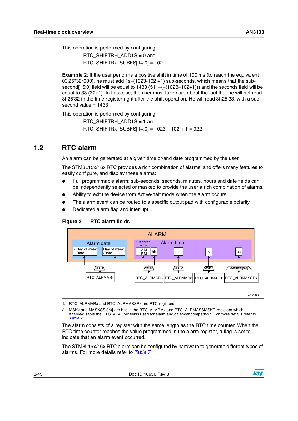
Figure 3. RTC alarm fields


!,!2-


!LARMMDATE

H OR H


!LARMMTIME


FORMAT


$AYYOF WEEK


$AYYOF WEEK

!-

HH

MM

S

SS

$ATE

$ATE

0-


-3+

-3+

-3+

-3+

-!3+33; =

24#?!,2-!2

24#?!,2-!2 24#?!,2-!2 24#?!,2-!2 24#?!,2-!332X


AI

1.RTC_ALRMARx and RTC_ALRMASSRx are RTC registers.

2.MSKx and MASKSS[3:0] are bits in the RTC_ALARMx and RTC_ALRMASSMSKR registers which enable/disable the RTC_ALARMx fields used for alarm and calendar comparison. For more details refer to

Table 7.

The alarm consists of a register with the same length as the RTC time counter. When the RTC time counter reaches the value programmed in the alarm register, a flag is set to indicate that an alarm event occurred.

The STM8L15x/16x RTC alarm can be configured by hardware to generate different types of alarms. For more details refer to Table 7.

8/43

Doc ID 16956 Rev 3

AN3133

Real-time clock overview


1.3RTC periodic wakeup unit

Like many low consumption microcontrollers, STM8L15x/16x microcontrollers provide several low power modes to reduce power consumption.

STM8L15x/16x microcontrollers feature a periodic timebase and wakeup unit that can wake up the system when the device operates in low power mode. This unit is a programmable downcounting auto-reload timer. When this counter reaches zero, a flag and an interrupt (if enabled) are generated.

The wakeup unit has the following features:

Programmable downcounting auto-reload timer

Specific flag and interrupt capable of waking up the device from low power modes

Wakeup alternate function output which can be routed to RTC_ALARM output (unique pad for both Alarm and Wakeup events) with configurable polarity

A full set of prescalers to select the desired waiting period

1.4RTC smooth digital calibration

The RTC clock frequency can be digitally calibrated by a series of small adjustments by adding or subtracting RTC clock cycles.

The RTC calibration block is designed to compensate the accuracy of typical crystal oscillators.

Crystal accuracy is highly dependant on:

Temperature

Crystal aging

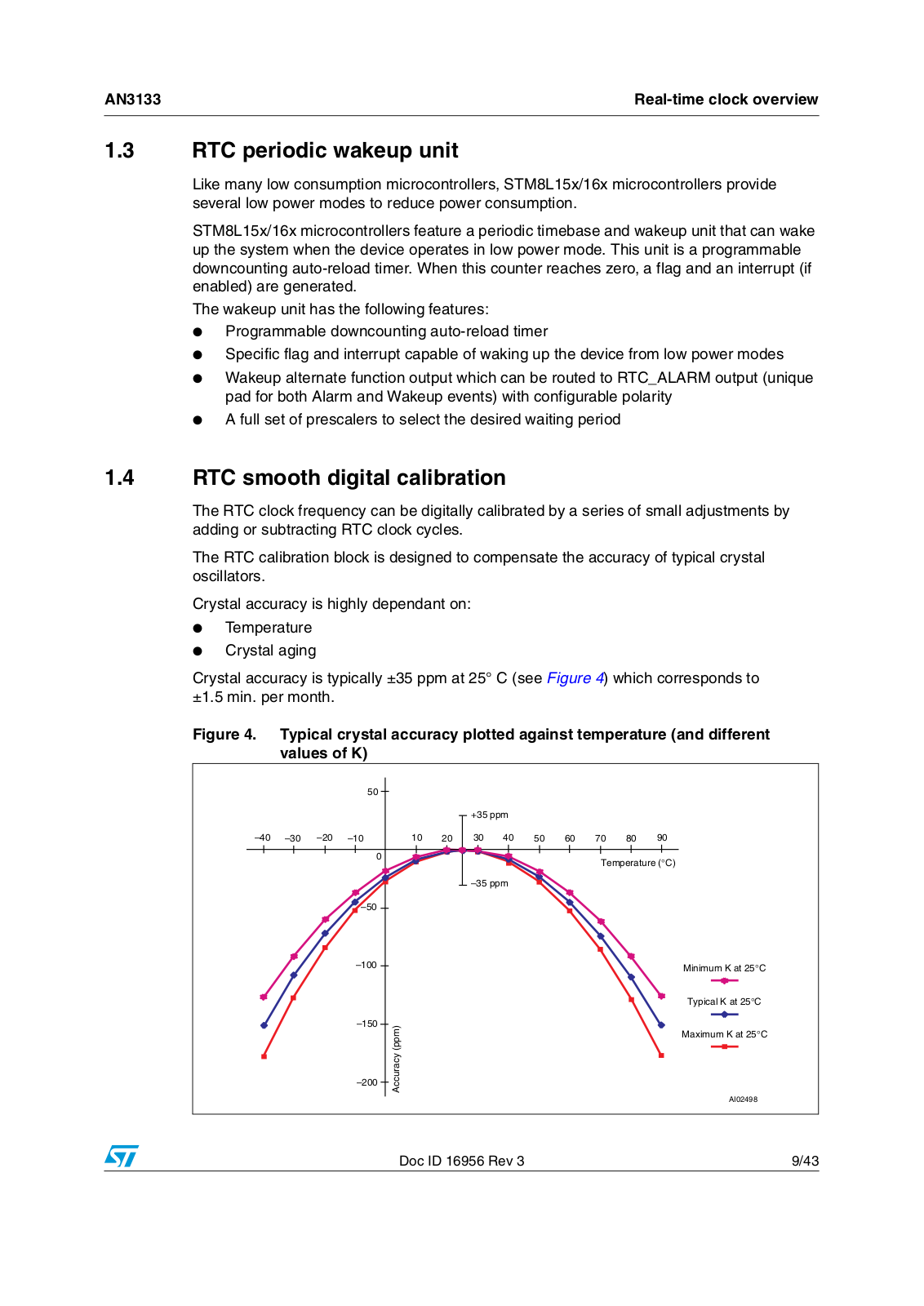
Crystal accuracy is typically ±35 ppm at 25° C (see Figure 4) which corresponds to ±1.5 min. per month.

Figure 4. Typical crystal accuracy plotted against temperature (and different values of K)


50

–40

–30

–20

–10


0


–50


–100


–150


–200

+35 ppm

10

20

30

40

50

60

70

80

90


Temperature (°C)

–35 ppm

Accuracy (ppm)

Minimum K at 25°C

Typical K at 25°C

Maximum K at 25°C

AI02498

Doc ID 16956 Rev 3

9/43

Real-time clock overview

AN3133


In Figure 4, accuracy = K x (T – TO)2

where, TO = 25° C ±5° C and K = –0.036 ppm/°C2 ± 0.006 ppm/°C2

RTC clock smooth digital calibration consists in masking N (configurable) 32 kHz clock pulses that are fairly well distributed in a configurable window (8s, 16s or 32s).

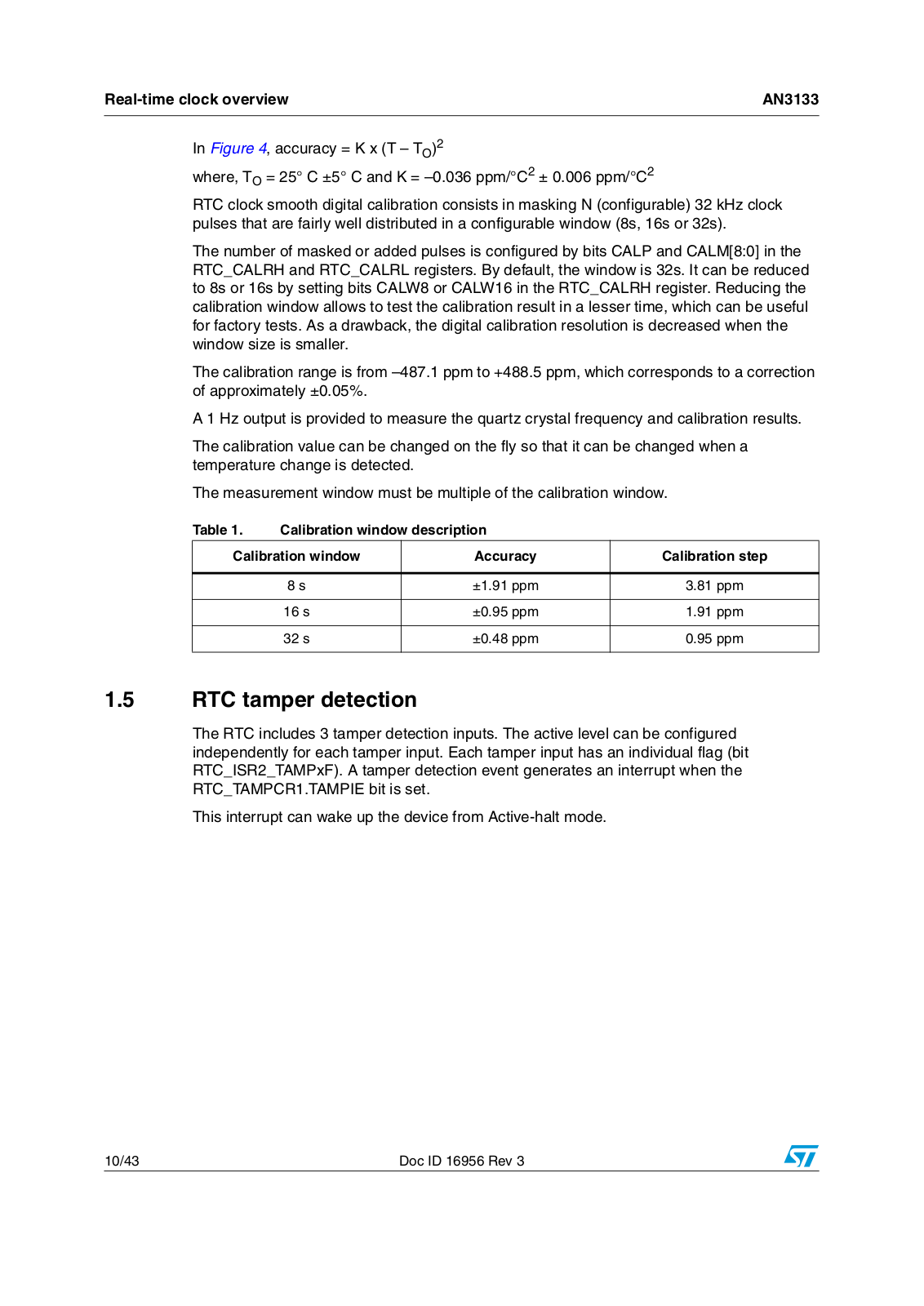
The number of masked or added pulses is configured by bits CALP and CALM[8:0] in the RTC_CALRH and RTC_CALRL registers. By default, the window is 32s. It can be reduced to 8s or 16s by setting bits CALW8 or CALW16 in the RTC_CALRH register. Reducing the calibration window allows to test the calibration result in a lesser time, which can be useful for factory tests. As a drawback, the digital calibration resolution is decreased when the window size is smaller.

The calibration range is from –487.1 ppm to +488.5 ppm, which corresponds to a correction of approximately ±0.05%.

A 1 Hz output is provided to measure the quartz crystal frequency and calibration results.

The calibration value can be changed on the fly so that it can be changed when a temperature change is detected.

The measurement window must be multiple of the calibration window.

Table 1.

Calibration window description


Calibration window

Accuracy

Calibration step


8 s

±1.91 ppm

3.81 ppm


16 s

±0.95 ppm

1.91 ppm


32 s

±0.48 ppm

0.95 ppm


1.5RTC tamper detection

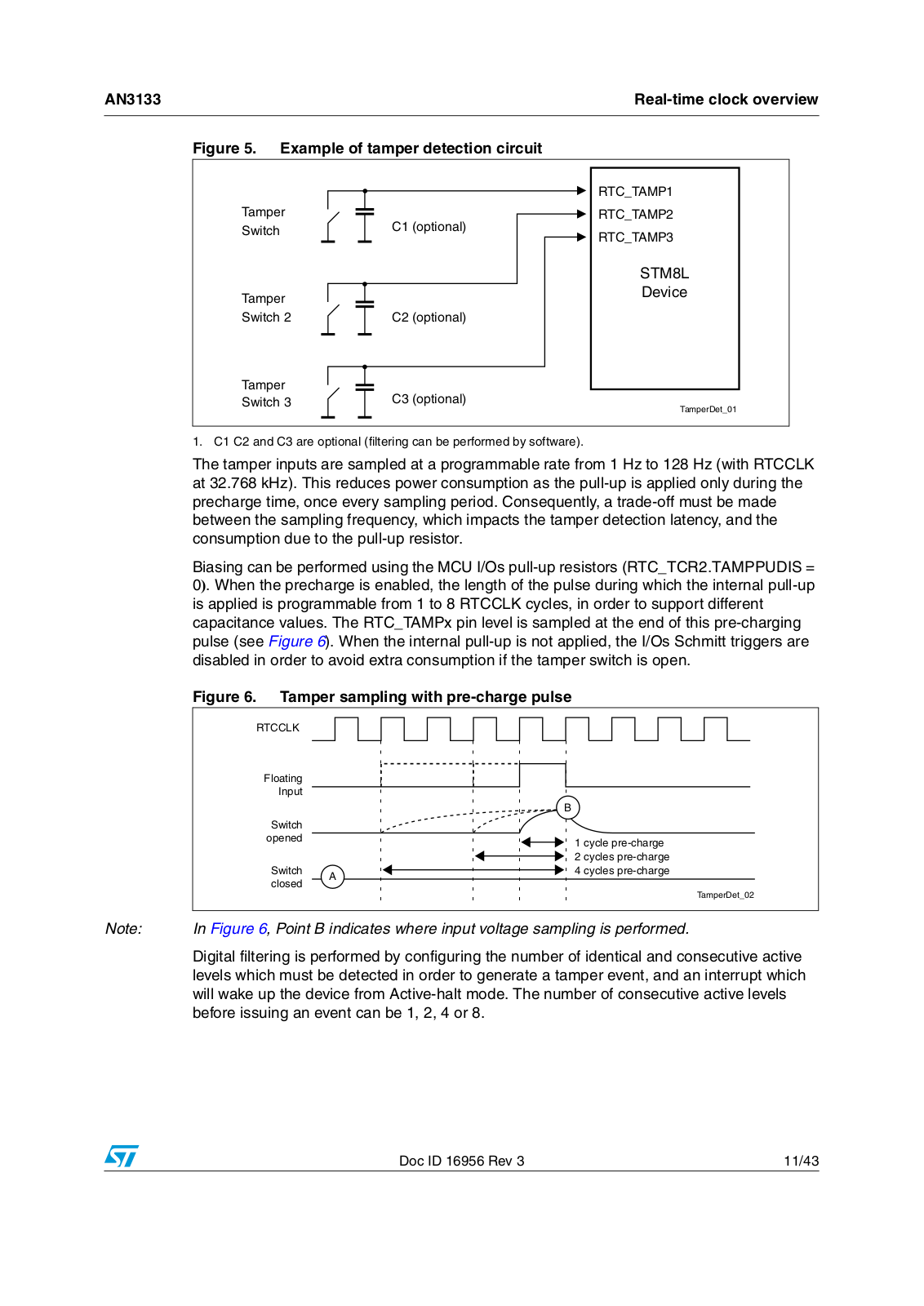
The RTC includes 3 tamper detection inputs. The active level can be configured independently for each tamper input. Each tamper input has an individual flag (bit RTC_ISR2_TAMPxF). A tamper detection event generates an interrupt when the RTC_TAMPCR1.TAMPIE bit is set.

This interrupt can wake up the device from Active-halt mode.

10/43

Doc ID 16956 Rev 3

ST AN3133 Application note

AN3133

Real-time clock overview


Figure 5. Example of tamper detection circuit


24#?4!-0

4AMPERP

24#?4!-0

3WITCH

# OPTIONAL

24#?4!-0


34- ,

4AMPERP

$EVICE


3WITCH

# OPTIONAL

4AMPERP

# OPTIONAL

3WITCH


4AMPER$ET?

1. C1 C2 and C3 are optional (filtering can be performed by software).

The tamper inputs are sampled at a programmable rate from 1 Hz to 128 Hz (with RTCCLK at 32.768 kHz). This reduces power consumption as the pull-up is applied only during the precharge time, once every sampling period. Consequently, a trade-off must be made between the sampling frequency, which impacts the tamper detection latency, and the consumption due to the pull-up resistor.

Biasing can be performed using the MCU I/Os pull-up resistors (RTC_TCR2.TAMPPUDIS = 0). When the precharge is enabled, the length of the pulse during which the internal pull-up is applied is programmable from 1 to 8 RTCCLK cycles, in order to support different capacitance values. The RTC_TAMPx pin level is sampled at the end of this pre-charging pulse (see Figure 6). When the internal pull-up is not applied, the I/Os Schmitt triggers are disabled in order to avoid extra consumption if the tamper switch is open.

Figure 6. Tamper sampling with pre-charge pulse


24##,+#


&LOATING


)NPUT


"


3WITCH


OPENED


CYCLEYPRE CHARGE


CYCLES PRE CHARGE


3WITCH

!


CYCLES PRE CHARGE


CLOSED


4AMPER$ET?


Note:

In Figure 6, Point B indicates where input voltage sampling is performed.

Digital filtering is performed by configuring the number of identical and consecutive active levels which must be detected in order to generate a tamper event, and an interrupt which will wake up the device from Active-halt mode. The number of consecutive active levels before issuing an event can be 1, 2, 4 or 8.

Doc ID 16956 Rev 3

11/43

Real-time clock overview

AN3133


Figure 7. Example of tamper filtering

4!-0&2%1& 2 X 1 S


4!-0&2%1& 2 X 1 S


4!-0X&0INTERRUPT

3AMPLEDPLEVEL

3AMPLEDPLEVEL

3AMPLEDPLEVEL

3AMPLEDPLEVEL

24##,+#


4!-002#(0 2 X ( CYCLES


24#?4!-0X


4!-0&,44 X

3WITCH #LOSED


3WITCH /PEN

4AMPER$ET?


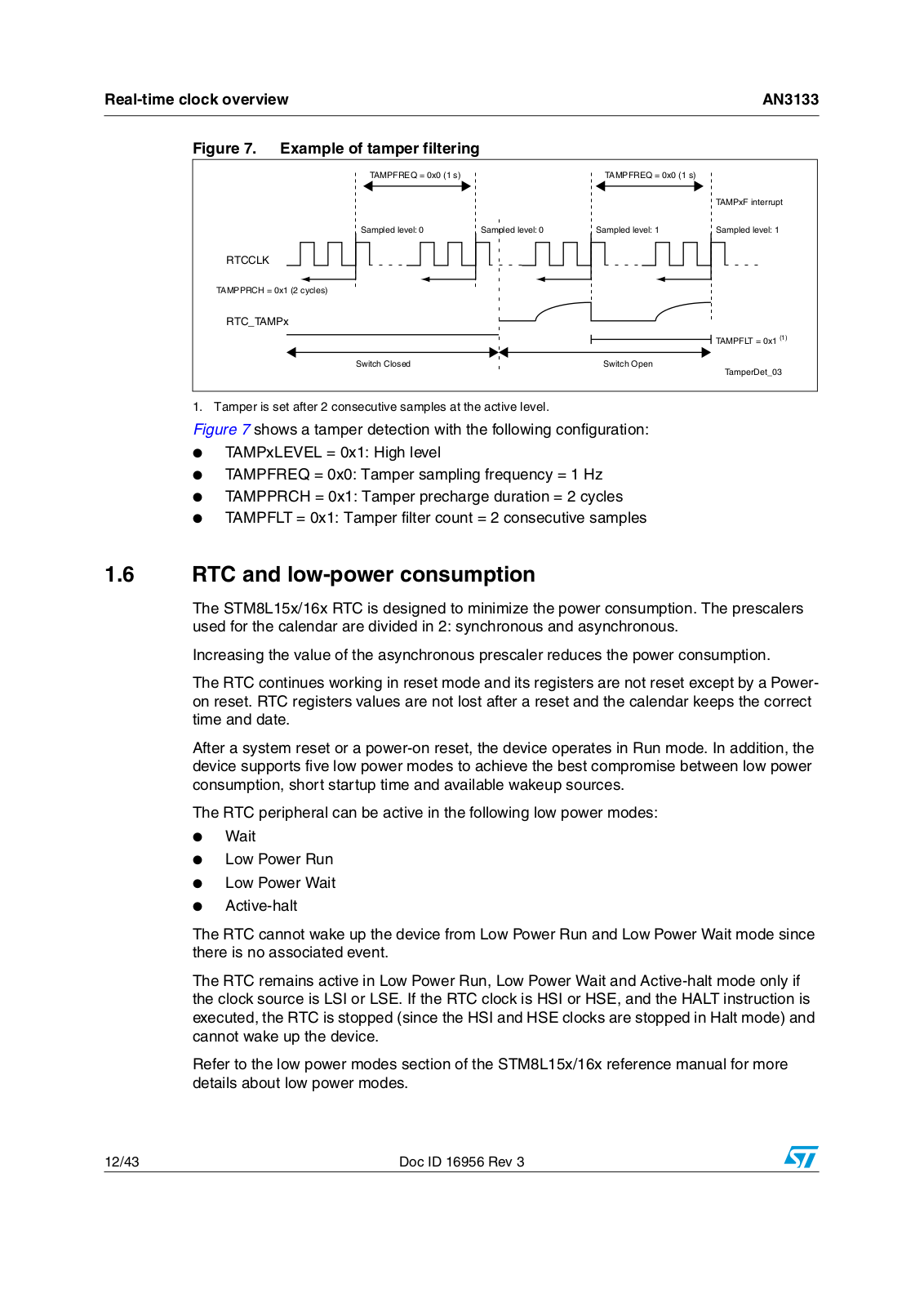
1. Tamper is set after 2 consecutive samples at the active level.

Figure 7 shows a tamper detection with the following configuration:

TAMPxLEVEL = 0x1: High level

TAMPFREQ = 0x0: Tamper sampling frequency = 1 Hz

TAMPPRCH = 0x1: Tamper precharge duration = 2 cycles

TAMPFLT = 0x1: Tamper filter count = 2 consecutive samples

1.6RTC and low-power consumption

The STM8L15x/16x RTC is designed to minimize the power consumption. The prescalers used for the calendar are divided in 2: synchronous and asynchronous.

Increasing the value of the asynchronous prescaler reduces the power consumption.

The RTC continues working in reset mode and its registers are not reset except by a Poweron reset. RTC registers values are not lost after a reset and the calendar keeps the correct time and date.

After a system reset or a power-on reset, the device operates in Run mode. In addition, the device supports five low power modes to achieve the best compromise between low power consumption, short startup time and available wakeup sources.

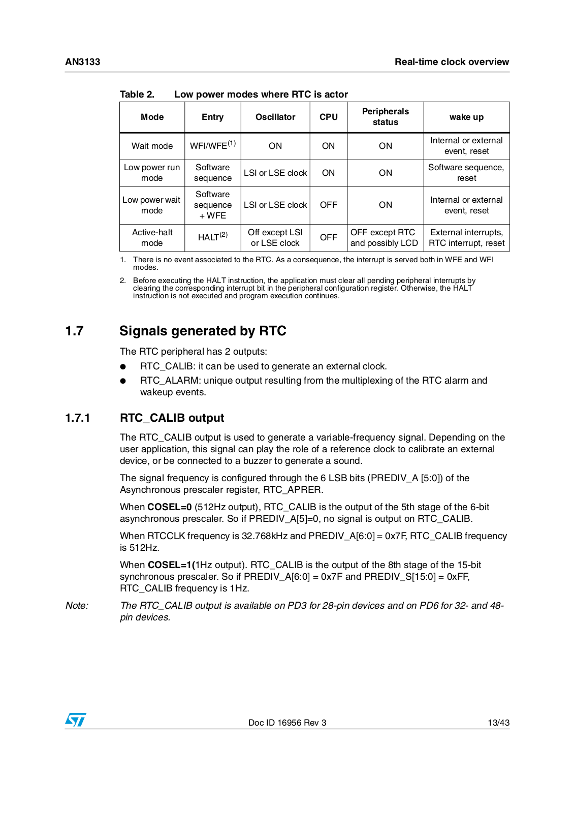
The RTC peripheral can be active in the following low power modes:

Wait

Low Power Run

Low Power Wait

Active-halt

The RTC cannot wake up the device from Low Power Run and Low Power Wait mode since there is no associated event.

The RTC remains active in Low Power Run, Low Power Wait and Active-halt mode only if the clock source is LSI or LSE. If the RTC clock is HSI or HSE, and the HALT instruction is executed, the RTC is stopped (since the HSI and HSE clocks are stopped in Halt mode) and cannot wake up the device.

Refer to the low power modes section of the STM8L15x/16x reference manual for more details about low power modes.

12/43

Doc ID 16956 Rev 3

AN3133


Real-time clock overview


Table 2.

Low power modes where RTC is actor


Mode


Entry

Oscillator

CPU


Peripherals

wake up


status


Wait mode


WFI/WFE(1)

ON

ON


ON

Internal or external


event, reset


Low power run

Software

LSI or LSE clock

ON


ON

Software sequence,


mode


sequence


reset


Low power wait

Software


Internal or external


sequence

LSI or LSE clock

OFF


ON


mode


event, reset


+ WFE


Active-halt


HALT(2)

Off except LSI

OFF


OFF except RTC

External interrupts,


mode


or LSE clock


and possibly LCD

RTC interrupt, reset


1.There is no event associated to the RTC. As a consequence, the interrupt is served both in WFE and WFI modes.

2.Before executing the HALT instruction, the application must clear all pending peripheral interrupts by clearing the corresponding interrupt bit in the peripheral configuration register. Otherwise, the HALT instruction is not executed and program execution continues.

1.7Signals generated by RTC

The RTC peripheral has 2 outputs:

RTC_CALIB: it can be used to generate an external clock.

RTC_ALARM: unique output resulting from the multiplexing of the RTC alarm and wakeup events.

1.7.1RTC_CALIB output


The RTC_CALIB output is used to generate a variable-frequency signal. Depending on the


user application, this signal can play the role of a reference clock to calibrate an external


device, or be connected to a buzzer to generate a sound.


The signal frequency is configured through the 6 LSB bits (PREDIV_A [5:0]) of the


Asynchronous prescaler register, RTC_APRER.


When COSEL=0 (512Hz output), RTC_CALIB is the output of the 5th stage of the 6-bit


asynchronous prescaler. So if PREDIV_A[5]=0, no signal is output on RTC_CALIB.


When RTCCLK frequency is 32.768kHz and PREDIV_A[6:0] = 0x7F, RTC_CALIB frequency


is 512Hz.


When COSEL=1(1Hz output). RTC_CALIB is the output of the 8th stage of the 15-bit


synchronous prescaler. So if PREDIV_A[6:0] = 0x7F and PREDIV_S[15:0] = 0xFF,


RTC_CALIB frequency is 1Hz.

Note:

The RTC_CALIB output is available on PD3 for 28-pin devices and on PD6 for 32and 48-


pin devices.

Doc ID 16956 Rev 3

13/43

Loading...
+ 30 hidden pages