

Page 1

AN3128
Application note
STM32 embedded graphic objects/touchscreen library
Introduction
This library is a firmware package which contains a collection of routines, data structures,
and macros covering the main features of a graphic library and supporting a HID device to
interact with the graphic objects (touchscreen, joystick, and pushbutton).
The library is general purpose and can be executed on any CPU, 8/16/32-bit, to guarantee
the maximum portability of any architecture or LCD controller, and it provides a graphical
user interface (GUI) for any application that operates with a graphical LCD.
While the firmware library functions with all currently available STM32 microcontrollers,
(STM32F10xxx, STM32L1xx and STM32F2xx series), this document describes the
firmware library through the implementation of a graphic library for embedded systems
based on the STM32F10xxx microcontroller family.
It can easily be used in the user application without an in-depth study of STM32 registers,
SPI, and I
significant time that would otherwise be spent in coding, while at the same time reducing the
application development and integration costs.
The firmware architecture is developed in separate layers and the HAL (hardware
abstraction layer) makes it independent from the microcontroller used in the final
application.
A set of fonts is included: 8x12 and 16x24.
Even though the firmware library source code is developed in 'ANSI-C', the code
architecture follows an OOP (object oriented programming) approach.
Section 1 describes the document and library rules.
Section 2 highlights the features of the STMPE811 and explains its hardware interface with
a device microcontroller (STM32 in this case).
Section 3 and 4 describe the library features, its architecture and its exported APIs
(application programming interfaces) in detail.
Section 5 contains an example application source code describing how to configure and use
the library.
Section 6 contains information about the embedded GUI resource editor application.
2
C read/write operation steps. As a result, using the firmware library saves
June 2011 Doc ID 16918 Rev 5 1/105
www.st.com
Page 2

Contents AN3128
Contents
1 Document and library rules . . . . . . . . . . . . . . . . . . . . . . . . . . . . . . . . . . 10
1.1 Acronyms . . . . . . . . . . . . . . . . . . . . . . . . . . . . . . . . . . . . . . . . . . . . . . . . . 10
2 Touchscreen controller hardware description . . . . . . . . . . . . . . . . . . . 11
2.1 Description . . . . . . . . . . . . . . . . . . . . . . . . . . . . . . . . . . . . . . . . . . . . . . . . 11
2.2 Features . . . . . . . . . . . . . . . . . . . . . . . . . . . . . . . . . . . . . . . . . . . . . . . . . . 11
2.3 STMPE811 functional overview . . . . . . . . . . . . . . . . . . . . . . . . . . . . . . . . 11
2.4 Touchscreen controller . . . . . . . . . . . . . . . . . . . . . . . . . . . . . . . . . . . . . . . 12
2.5 Interfacing touchscreen with microcontroller with the STMPE811 via I2C 13
3 Multi-input embedded GUI library . . . . . . . . . . . . . . . . . . . . . . . . . . . . . 14
3.1 Introduction . . . . . . . . . . . . . . . . . . . . . . . . . . . . . . . . . . . . . . . . . . . . . . . 14
3.2 Graphic object introduction . . . . . . . . . . . . . . . . . . . . . . . . . . . . . . . . . . . . 14
3.3 Library package . . . . . . . . . . . . . . . . . . . . . . . . . . . . . . . . . . . . . . . . . . . . 16
3.4 Library architecture . . . . . . . . . . . . . . . . . . . . . . . . . . . . . . . . . . . . . . . . . 19
3.4.1 API layer . . . . . . . . . . . . . . . . . . . . . . . . . . . . . . . . . . . . . . . . . . . . . . . . 19
3.4.2 HAL layer . . . . . . . . . . . . . . . . . . . . . . . . . . . . . . . . . . . . . . . . . . . . . . . . 19
4 Multi-input embedded GUI library firmware . . . . . . . . . . . . . . . . . . . . . 21
4.1 Graphic object API functions . . . . . . . . . . . . . . . . . . . . . . . . . . . . . . . . . . 21
4.1.1 NewLabel API global function . . . . . . . . . . . . . . . . . . . . . . . . . . . . . . . . 23
4.1.2 NewButton API global function . . . . . . . . . . . . . . . . . . . . . . . . . . . . . . . 24
4.1.3 NewCheckbox API global function . . . . . . . . . . . . . . . . . . . . . . . . . . . . . 25
4.1.4 NewSwitch API global function . . . . . . . . . . . . . . . . . . . . . . . . . . . . . . . 26
4.1.5 NewIcon API global function . . . . . . . . . . . . . . . . . . . . . . . . . . . . . . . . . 27
4.1.6 NewRadioButtonGrp API global function . . . . . . . . . . . . . . . . . . . . . . . . 28
4.1.7 AddRadioOption API global function . . . . . . . . . . . . . . . . . . . . . . . . . . . 28
4.1.8 NewComboBoxGrp API global function . . . . . . . . . . . . . . . . . . . . . . . . . 29
4.1.9 AddComboOption API global function . . . . . . . . . . . . . . . . . . . . . . . . . . 30
4.1.10 NewSlidebar API global function . . . . . . . . . . . . . . . . . . . . . . . . . . . . . . 31
4.1.11 NewHistogram API global function . . . . . . . . . . . . . . . . . . . . . . . . . . . . 33
4.1.12 NewGraphChart API global function . . . . . . . . . . . . . . . . . . . . . . . . . . . 35
4.1.13 AddPageControlObj API global function . . . . . . . . . . . . . . . . . . . . . . . . 36
2/105 Doc ID 16918 Rev 5
Page 3

AN3128 Contents
4.1.14 DestroyPageControl API global function . . . . . . . . . . . . . . . . . . . . . . . . 37
4.1.15 DestroyPage API global function . . . . . . . . . . . . . . . . . . . . . . . . . . . . . . 38
4.1.16 Set_Label API global function . . . . . . . . . . . . . . . . . . . . . . . . . . . . . . . . 38
4.1.17 Get_Label API global function . . . . . . . . . . . . . . . . . . . . . . . . . . . . . . . . 39
4.1.18 GetComboOptionLabel API global function . . . . . . . . . . . . . . . . . . . . . . 40
4.1.19 SetComboOptionLabel API global function . . . . . . . . . . . . . . . . . . . . . . 41
4.1.20 ResetComboOptionActive API global function . . . . . . . . . . . . . . . . . . . . 42
4.1.21 GetComboOptionActive API global function . . . . . . . . . . . . . . . . . . . . . 43
4.1.22 SetIconImage API global function . . . . . . . . . . . . . . . . . . . . . . . . . . . . . 44
4.1.23 Get_SlidebarValue API global function . . . . . . . . . . . . . . . . . . . . . . . . . 45
4.1.24 SetHistogramPoints API global function . . . . . . . . . . . . . . . . . . . . . . . . 46
4.1.25 SetGraphChartPoints API global function . . . . . . . . . . . . . . . . . . . . . . . 46
4.1.26 GetObjStatus API global function . . . . . . . . . . . . . . . . . . . . . . . . . . . . . 47
4.1.27 ShowPage API global function . . . . . . . . . . . . . . . . . . . . . . . . . . . . . . . . 48
4.1.28 RefreshPage API global function . . . . . . . . . . . . . . . . . . . . . . . . . . . . . . 49
4.1.29 RefreshPageControl API global function . . . . . . . . . . . . . . . . . . . . . . . . 50
4.1.30 ChangePage API global function . . . . . . . . . . . . . . . . . . . . . . . . . . . . . . 51
4.1.31 Set_LCD_Resolution API global function . . . . . . . . . . . . . . . . . . . . . . . 52
4.1.32 Set_LastFlashMemoryAddress API global function . . . . . . . . . . . . . . . . 52
4.1.33 CursorInit API global function . . . . . . . . . . . . . . . . . . . . . . . . . . . . . . . . 53
4.1.34 CursorShow API global function . . . . . . . . . . . . . . . . . . . . . . . . . . . . . . 54
4.2 Graphic objects API types . . . . . . . . . . . . . . . . . . . . . . . . . . . . . . . . . . . . 57
4.2.1 GL_ErrStatus type . . . . . . . . . . . . . . . . . . . . . . . . . . . . . . . . . . . . . . . . . 58
4.2.2 GL_Direction type . . . . . . . . . . . . . . . . . . . . . . . . . . . . . . . . . . . . . . . . . 58
4.2.3 GL_ButtonStatus type . . . . . . . . . . . . . . . . . . . . . . . . . . . . . . . . . . . . . . 58
4.2.4 GL_ObjType type . . . . . . . . . . . . . . . . . . . . . . . . . . . . . . . . . . . . . . . . . . 58
4.2.5 GL_Coordinate_TypeDef type . . . . . . . . . . . . . . . . . . . . . . . . . . . . . . . . 58
4.2.6 GL_PageControls_TypeDef type . . . . . . . . . . . . . . . . . . . . . . . . . . . . . . 58
4.2.7 GL_Label_TypeDef type . . . . . . . . . . . . . . . . . . . . . . . . . . . . . . . . . . . . 59
4.2.8 GL_Button_TypeDef type . . . . . . . . . . . . . . . . . . . . . . . . . . . . . . . . . . . . 59
4.2.9 GL_CheckboxObj_TypeDef type . . . . . . . . . . . . . . . . . . . . . . . . . . . . . . 59
4.2.10 GL_SwitchObj_TypeDef type . . . . . . . . . . . . . . . . . . . . . . . . . . . . . . . . . 60
4.2.11 GL_RadioButtonGrp_TypeDef type . . . . . . . . . . . . . . . . . . . . . . . . . . . . 60
4.2.12 GL_RadioButton_TypeDef type . . . . . . . . . . . . . . . . . . . . . . . . . . . . . . . 60
4.2.13 GL_ComboBoxGrp_TypeDef type . . . . . . . . . . . . . . . . . . . . . . . . . . . . . 61
4.2.14 GL_ComboOption_TypeDef type . . . . . . . . . . . . . . . . . . . . . . . . . . . . . . 61
4.2.15 GL_Icon_TypeDef type . . . . . . . . . . . . . . . . . . . . . . . . . . . . . . . . . . . . . 61
Doc ID 16918 Rev 5 3/105
Page 4

Contents AN3128
4.2.16 GL_Slidebar_TypeDef type . . . . . . . . . . . . . . . . . . . . . . . . . . . . . . . . . . 62
4.2.17 GL_Histogram_TypeDef type . . . . . . . . . . . . . . . . . . . . . . . . . . . . . . . . . 62
4.2.18 GL_GraphChart_TypeDef type . . . . . . . . . . . . . . . . . . . . . . . . . . . . . . . 62
4.2.19 GL_ObjDimensions_TypeDef type . . . . . . . . . . . . . . . . . . . . . . . . . . . . . 63
4.2.20 GL_Page_TypeDef type . . . . . . . . . . . . . . . . . . . . . . . . . . . . . . . . . . . . . 63
4.2.21 GL_BusType type . . . . . . . . . . . . . . . . . . . . . . . . . . . . . . . . . . . . . . . . . 63
4.2.22 LCD_HW_Parameters_TypeDef type . . . . . . . . . . . . . . . . . . . . . . . . . . 63
4.2.23 TSC_HW_Parameters_TypeDef type . . . . . . . . . . . . . . . . . . . . . . . . . . 64
4.2.24 JOY_HW_Parameters_TypeDef type . . . . . . . . . . . . . . . . . . . . . . . . . . . 64
4.2.25 JOY_ReadMode type . . . . . . . . . . . . . . . . . . . . . . . . . . . . . . . . . . . . . . . 64
4.2.26 BTN_HW_Parameters_TypeDef type . . . . . . . . . . . . . . . . . . . . . . . . . . 65
4.3 Graphic object API properties . . . . . . . . . . . . . . . . . . . . . . . . . . . . . . . . . 65
4.3.1 Graphics controls:: properties . . . . . . . . . . . . . . . . . . . . . . . . . . . . . . . . 65
4.3.2 Graphic Object:: PagesList array . . . . . . . . . . . . . . . . . . . . . . . . . . . . . . 65
4.3.3 LCD:: pLcdParam API properties . . . . . . . . . . . . . . . . . . . . . . . . . . . . . 65
4.3.4 Touchscreen:: pTscParam API properties . . . . . . . . . . . . . . . . . . . . . . . 67
4.3.5 Joystick:: pJoyParam API properties . . . . . . . . . . . . . . . . . . . . . . . . . . . 68
4.3.6 Push user button:: pBtnParam API properties . . . . . . . . . . . . . . . . . . . . 70
4.4 HAL layer firmware overview . . . . . . . . . . . . . . . . . . . . . . . . . . . . . . . . . . 71
4.5 HAL types . . . . . . . . . . . . . . . . . . . . . . . . . . . . . . . . . . . . . . . . . . . . . . . . . 71
4.5.1 GL_bool type . . . . . . . . . . . . . . . . . . . . . . . . . . . . . . . . . . . . . . . . . . . . . 71
4.5.2 GL_FlagStatus/GL_ITStatus type . . . . . . . . . . . . . . . . . . . . . . . . . . . . . 71
4.5.3 GL_SignalActionType type . . . . . . . . . . . . . . . . . . . . . . . . . . . . . . . . . . . 71
4.5.4 GL_FunctionalState type . . . . . . . . . . . . . . . . . . . . . . . . . . . . . . . . . . . . 71
4.5.5 TSC_I2C_SettingsType type . . . . . . . . . . . . . . . . . . . . . . . . . . . . . . . . . 71
4.5.6 TSC_Flash_TestStatus type . . . . . . . . . . . . . . . . . . . . . . . . . . . . . . . . . 72
4.5.7 GL_LCD_TypeDef type . . . . . . . . . . . . . . . . . . . . . . . . . . . . . . . . . . . . . 72
4.6 HAL functions . . . . . . . . . . . . . . . . . . . . . . . . . . . . . . . . . . . . . . . . . . . . . . 72
4.6.1 NewLcdHwParamObj HAL function . . . . . . . . . . . . . . . . . . . . . . . . . . . . 72
4.6.2 GL_SetTextColor HAL function . . . . . . . . . . . . . . . . . . . . . . . . . . . . . . . 72
4.6.3 GL_SetBackColor HAL function . . . . . . . . . . . . . . . . . . . . . . . . . . . . . . . 73
4.6.4 GL_Clear HAL function . . . . . . . . . . . . . . . . . . . . . . . . . . . . . . . . . . . . . 73
4.6.5 GL_LCD_DrawCharTransparent HAL function . . . . . . . . . . . . . . . . . . . 74
4.6.6 GL_LCD_DrawChar HAL function . . . . . . . . . . . . . . . . . . . . . . . . . . . . . 74
4.6.7 GL_DisplayAdjStringLine HAL function . . . . . . . . . . . . . . . . . . . . . . . . . 75
4.6.8 GL_LCD_DisplayChar HAL function . . . . . . . . . . . . . . . . . . . . . . . . . . . 75
4.6.9 GL_SetDisplayWindow HAL function . . . . . . . . . . . . . . . . . . . . . . . . . . . 76
4.6.10 GL_DrawLine HAL function . . . . . . . . . . . . . . . . . . . . . . . . . . . . . . . . . . 76
4/105 Doc ID 16918 Rev 5
Page 5

AN3128 Contents
4.6.11 GL_DrawBMP HAL function . . . . . . . . . . . . . . . . . . . . . . . . . . . . . . . . . 77
4.6.12 GL_SetFont HAL function . . . . . . . . . . . . . . . . . . . . . . . . . . . . . . . . . . . 77
4.6.13 GL_BackLightSwitch HAL function . . . . . . . . . . . . . . . . . . . . . . . . . . . . 77
4.6.14 GL_BUSConfig HAL function . . . . . . . . . . . . . . . . . . . . . . . . . . . . . . . . . 78
4.6.15 GL_LCD_Init HAL function . . . . . . . . . . . . . . . . . . . . . . . . . . . . . . . . . . 78
4.6.16 NewTscHwParamObj HAL function . . . . . . . . . . . . . . . . . . . . . . . . . . . . 79
4.6.17 NewJoyHwParamObj HAL function . . . . . . . . . . . . . . . . . . . . . . . . . . . . 79
4.6.18 NewBtnHwParamObj HAL function . . . . . . . . . . . . . . . . . . . . . . . . . . . . 79
4.6.19 GL_GPIO_Init HAL function . . . . . . . . . . . . . . . . . . . . . . . . . . . . . . . . . . 80
4.6.20 GL_SPI_Init HAL function . . . . . . . . . . . . . . . . . . . . . . . . . . . . . . . . . . . 80
4.6.21 GL_NVIC_SetVectorTable HAL function . . . . . . . . . . . . . . . . . . . . . . . . 81
4.6.22 GL_NVIC_Init HAL function . . . . . . . . . . . . . . . . . . . . . . . . . . . . . . . . . . 81
4.6.23 GL_NVIC_PriorityGroupConfig HAL function . . . . . . . . . . . . . . . . . . . . 82
4.6.24 GL_EXTI_DeInit HAL function . . . . . . . . . . . . . . . . . . . . . . . . . . . . . . . . 82
4.6.25 GL_EXTI_Init HAL function . . . . . . . . . . . . . . . . . . . . . . . . . . . . . . . . . . 83
4.6.26 GL_GPIO_EXTILineConfig HAL function . . . . . . . . . . . . . . . . . . . . . . . 83
4.6.27 GL_EXTI_TSC_IRQHandler HAL function . . . . . . . . . . . . . . . . . . . . . . 84
4.6.28 GL_TSC_Interface_Init HAL function . . . . . . . . . . . . . . . . . . . . . . . . . . . 84
4.6.29 GL_JOY_Interface_Init HAL function . . . . . . . . . . . . . . . . . . . . . . . . . . . 85
4.6.30 GL_JoyStickConfig_IOExpander HAL function . . . . . . . . . . . . . . . . . . . 85
4.6.31 GL_JoyStickConfig_GPIO HAL function . . . . . . . . . . . . . . . . . . . . . . . . 85
4.6.32 GL_JoyStickStateIOEXP HAL function . . . . . . . . . . . . . . . . . . . . . . . . . 86
4.6.33 GL_JoyStickStatePolling HAL function . . . . . . . . . . . . . . . . . . . . . . . . . 86
4.6.34 GL_Delay HAL function . . . . . . . . . . . . . . . . . . . . . . . . . . . . . . . . . . . . . 87
4.6.35 TSC_Read HAL function . . . . . . . . . . . . . . . . . . . . . . . . . . . . . . . . . . . . 88
4.6.36 TSC_FLASH_Unlock HAL function . . . . . . . . . . . . . . . . . . . . . . . . . . . . 88
4.6.37 TSC_FLASH_ClearFlag HAL function . . . . . . . . . . . . . . . . . . . . . . . . . . 88
4.6.38 TSC_FLASH_ErasePage HAL function . . . . . . . . . . . . . . . . . . . . . . . . . 89
4.6.39 TSC_FLASH_ProgramWord HAL function . . . . . . . . . . . . . . . . . . . . . . 89
4.6.40 GL_GPIO_ReadInputDataBit HAL function . . . . . . . . . . . . . . . . . . . . . . 90
4.6.41 GL_LCD_CtrlLinesWrite HAL function . . . . . . . . . . . . . . . . . . . . . . . . . . 90
4.6.42 GL_LCD_ReadRAM HAL function . . . . . . . . . . . . . . . . . . . . . . . . . . . . . 91
4.6.43 GL_RCC_APBPeriphClockCmd HAL function . . . . . . . . . . . . . . . . . . . . 91
4.6.44 GL_RCC_AHBPeriphClockCmd HAL function . . . . . . . . . . . . . . . . . . . 92
5 Getting started with the system . . . . . . . . . . . . . . . . . . . . . . . . . . . . . . . 94
5.1 Example application - main.c . . . . . . . . . . . . . . . . . . . . . . . . . . . . . . . . . . 94
Doc ID 16918 Rev 5 5/105
Page 6

Contents AN3128
6 Embedded GUI resource editor application . . . . . . . . . . . . . . . . . . . . . 97
6.1 Introduction . . . . . . . . . . . . . . . . . . . . . . . . . . . . . . . . . . . . . . . . . . . . . . . 97
6.2 Resource editor application: quick start . . . . . . . . . . . . . . . . . . . . . . . . . . 98
6.3 Description of the generated files . . . . . . . . . . . . . . . . . . . . . . . . . . . . . . 101
6.4 Integration with the embedded project . . . . . . . . . . . . . . . . . . . . . . . . . . 102
7 References . . . . . . . . . . . . . . . . . . . . . . . . . . . . . . . . . . . . . . . . . . . . . . . 103
8 Revision history . . . . . . . . . . . . . . . . . . . . . . . . . . . . . . . . . . . . . . . . . . 104
6/105 Doc ID 16918 Rev 5
Page 7

AN3128 List of tables
List of tables
Table 1. List of acronyms . . . . . . . . . . . . . . . . . . . . . . . . . . . . . . . . . . . . . . . . . . . . . . . . . . . . . . . . . 10
Table 2. ROM usage of graphic objects . . . . . . . . . . . . . . . . . . . . . . . . . . . . . . . . . . . . . . . . . . . . . . 15
Table 3. RAM usage of graphic objects . . . . . . . . . . . . . . . . . . . . . . . . . . . . . . . . . . . . . . . . . . . . . . 15
Table 4. ROM usage of font sets . . . . . . . . . . . . . . . . . . . . . . . . . . . . . . . . . . . . . . . . . . . . . . . . . . . 16
Table 5. Function description format . . . . . . . . . . . . . . . . . . . . . . . . . . . . . . . . . . . . . . . . . . . . . . . . 21
Table 6. NewLabel API function . . . . . . . . . . . . . . . . . . . . . . . . . . . . . . . . . . . . . . . . . . . . . . . . . . . . 23
Table 7. NewButton API function . . . . . . . . . . . . . . . . . . . . . . . . . . . . . . . . . . . . . . . . . . . . . . . . . . . 24
Table 8. NewCheckbox API function . . . . . . . . . . . . . . . . . . . . . . . . . . . . . . . . . . . . . . . . . . . . . . . . 25
Table 9. NewSwitch API function . . . . . . . . . . . . . . . . . . . . . . . . . . . . . . . . . . . . . . . . . . . . . . . . . . . 26
Table 10. NewIcon API function . . . . . . . . . . . . . . . . . . . . . . . . . . . . . . . . . . . . . . . . . . . . . . . . . . . . . 27
Table 11. NewRadioButtonGrp API function . . . . . . . . . . . . . . . . . . . . . . . . . . . . . . . . . . . . . . . . . . . 28
Table 12. AddRadioOption API function . . . . . . . . . . . . . . . . . . . . . . . . . . . . . . . . . . . . . . . . . . . . . . . 28
Table 13. NewComboBoxGrp API function . . . . . . . . . . . . . . . . . . . . . . . . . . . . . . . . . . . . . . . . . . . . 30
Table 14. AddComboOption API function . . . . . . . . . . . . . . . . . . . . . . . . . . . . . . . . . . . . . . . . . . . . . . 30
Table 15. NewSlidebar API function . . . . . . . . . . . . . . . . . . . . . . . . . . . . . . . . . . . . . . . . . . . . . . . . . . 32
Table 16. NewHistogram API function . . . . . . . . . . . . . . . . . . . . . . . . . . . . . . . . . . . . . . . . . . . . . . . . 33
Table 17. NewGraphChart API function . . . . . . . . . . . . . . . . . . . . . . . . . . . . . . . . . . . . . . . . . . . . . . . 35
Table 18. AddPageControlObj API function . . . . . . . . . . . . . . . . . . . . . . . . . . . . . . . . . . . . . . . . . . . . 36
Table 19. DestroyPageControl API function . . . . . . . . . . . . . . . . . . . . . . . . . . . . . . . . . . . . . . . . . . . . 37
Table 20. DestroyPage API function. . . . . . . . . . . . . . . . . . . . . . . . . . . . . . . . . . . . . . . . . . . . . . . . . . 38
Table 21. Set_Label API function . . . . . . . . . . . . . . . . . . . . . . . . . . . . . . . . . . . . . . . . . . . . . . . . . . . . 38
Table 22. Get_Label API function . . . . . . . . . . . . . . . . . . . . . . . . . . . . . . . . . . . . . . . . . . . . . . . . . . . . 39
Table 23. GetComboOptionLabel API function. . . . . . . . . . . . . . . . . . . . . . . . . . . . . . . . . . . . . . . . . . 40
Table 24. SetComboOptionLabel API function . . . . . . . . . . . . . . . . . . . . . . . . . . . . . . . . . . . . . . . . . . 41
Table 25. ResetComboOptionActive API function . . . . . . . . . . . . . . . . . . . . . . . . . . . . . . . . . . . . . . . 42
Table 26. GetComboOptionActive API function . . . . . . . . . . . . . . . . . . . . . . . . . . . . . . . . . . . . . . . . . 43
Table 27. SetIconImage API function . . . . . . . . . . . . . . . . . . . . . . . . . . . . . . . . . . . . . . . . . . . . . . . . . 44
Table 28. Get_SlidebarValue API function . . . . . . . . . . . . . . . . . . . . . . . . . . . . . . . . . . . . . . . . . . . . . 45
Table 29. SetHistogramPoints API function . . . . . . . . . . . . . . . . . . . . . . . . . . . . . . . . . . . . . . . . . . . . 46
Table 30. SetGraphChartPoints API function . . . . . . . . . . . . . . . . . . . . . . . . . . . . . . . . . . . . . . . . . . . 46
Table 31. GetObjStatus API function . . . . . . . . . . . . . . . . . . . . . . . . . . . . . . . . . . . . . . . . . . . . . . . . . 47
Table 32. ShowPage API function . . . . . . . . . . . . . . . . . . . . . . . . . . . . . . . . . . . . . . . . . . . . . . . . . . . 48
Table 33. RefreshPage API function . . . . . . . . . . . . . . . . . . . . . . . . . . . . . . . . . . . . . . . . . . . . . . . . . 49
Table 34. RefreshPage API function . . . . . . . . . . . . . . . . . . . . . . . . . . . . . . . . . . . . . . . . . . . . . . . . . 50
Table 35. ChangePage API function . . . . . . . . . . . . . . . . . . . . . . . . . . . . . . . . . . . . . . . . . . . . . . . . . 51
Table 36. Set_LCD_Resolution API global function . . . . . . . . . . . . . . . . . . . . . . . . . . . . . . . . . . . . . . 52
Table 37. Set_LastFlashMemoryAddress API global function . . . . . . . . . . . . . . . . . . . . . . . . . . . . . . 52
Table 38. CursorInit API global function . . . . . . . . . . . . . . . . . . . . . . . . . . . . . . . . . . . . . . . . . . . . . . . 53
Table 39. CursorShow API function . . . . . . . . . . . . . . . . . . . . . . . . . . . . . . . . . . . . . . . . . . . . . . . . . . 54
Table 40. NewLcdHwParamObj . . . . . . . . . . . . . . . . . . . . . . . . . . . . . . . . . . . . . . . . . . . . . . . . . . . . . 72
Table 41. GL_SetTextColor . . . . . . . . . . . . . . . . . . . . . . . . . . . . . . . . . . . . . . . . . . . . . . . . . . . . . . . . 72
Table 42. GL_SetBackColor . . . . . . . . . . . . . . . . . . . . . . . . . . . . . . . . . . . . . . . . . . . . . . . . . . . . . . . . 73
Table 43. GL_Clear . . . . . . . . . . . . . . . . . . . . . . . . . . . . . . . . . . . . . . . . . . . . . . . . . . . . . . . . . . . . . . 73
Table 44. GL_LCD_DrawCharTransparent HAL function . . . . . . . . . . . . . . . . . . . . . . . . . . . . . . . . . . 74
Table 45. GL_LCD_DrawChar HAL function . . . . . . . . . . . . . . . . . . . . . . . . . . . . . . . . . . . . . . . . . . . 74
Table 46. GL_DisplayAdjStringLine . . . . . . . . . . . . . . . . . . . . . . . . . . . . . . . . . . . . . . . . . . . . . . . . . . 75
Table 47. GL_LCD_DisplayChar . . . . . . . . . . . . . . . . . . . . . . . . . . . . . . . . . . . . . . . . . . . . . . . . . . . . 75
Table 48. GL_SetDisplayWindow . . . . . . . . . . . . . . . . . . . . . . . . . . . . . . . . . . . . . . . . . . . . . . . . . . . . 76
Doc ID 16918 Rev 5 7/105
Page 8

List of tables AN3128
Table 49. GL_DrawLine . . . . . . . . . . . . . . . . . . . . . . . . . . . . . . . . . . . . . . . . . . . . . . . . . . . . . . . . . . . 76
Table 50. GL_DrawBMP . . . . . . . . . . . . . . . . . . . . . . . . . . . . . . . . . . . . . . . . . . . . . . . . . . . . . . . . . . . 77
Table 51. GL_SetFont . . . . . . . . . . . . . . . . . . . . . . . . . . . . . . . . . . . . . . . . . . . . . . . . . . . . . . . . . . . . 77
Table 52. GL_BackLightSwitch. . . . . . . . . . . . . . . . . . . . . . . . . . . . . . . . . . . . . . . . . . . . . . . . . . . . . . 77
Table 53. GL_BUSConfig . . . . . . . . . . . . . . . . . . . . . . . . . . . . . . . . . . . . . . . . . . . . . . . . . . . . . . . . . . 78
Table 54. GL_LCD_Init . . . . . . . . . . . . . . . . . . . . . . . . . . . . . . . . . . . . . . . . . . . . . . . . . . . . . . . . . . . . 78
Table 55. NewTscHwParamObj . . . . . . . . . . . . . . . . . . . . . . . . . . . . . . . . . . . . . . . . . . . . . . . . . . . . . 79
Table 56. NewJoyHwParamObj . . . . . . . . . . . . . . . . . . . . . . . . . . . . . . . . . . . . . . . . . . . . . . . . . . . . . 79
Table 57. NewBtnHwParamObj HAL . . . . . . . . . . . . . . . . . . . . . . . . . . . . . . . . . . . . . . . . . . . . . . . . . 79
Table 58. GL_GPIO_Init . . . . . . . . . . . . . . . . . . . . . . . . . . . . . . . . . . . . . . . . . . . . . . . . . . . . . . . . . . . 80
Table 59. GL_SPI_Init . . . . . . . . . . . . . . . . . . . . . . . . . . . . . . . . . . . . . . . . . . . . . . . . . . . . . . . . . . . . 80
Table 60. GL_NVIC_SetVectorTable . . . . . . . . . . . . . . . . . . . . . . . . . . . . . . . . . . . . . . . . . . . . . . . . . 81
Table 61. GL_NVIC_Init . . . . . . . . . . . . . . . . . . . . . . . . . . . . . . . . . . . . . . . . . . . . . . . . . . . . . . . . . . . 81
Table 62. GL_NVIC_PriorityGroupConfig . . . . . . . . . . . . . . . . . . . . . . . . . . . . . . . . . . . . . . . . . . . . . . 82
Table 63. GL_EXTI_DeInit . . . . . . . . . . . . . . . . . . . . . . . . . . . . . . . . . . . . . . . . . . . . . . . . . . . . . . . . . 82
Table 64. GL_EXTI_Init . . . . . . . . . . . . . . . . . . . . . . . . . . . . . . . . . . . . . . . . . . . . . . . . . . . . . . . . . . . 83
Table 65. GL_GPIO_EXTILineConfig . . . . . . . . . . . . . . . . . . . . . . . . . . . . . . . . . . . . . . . . . . . . . . . . . 83
Table 66. GL_EXTI_TSC_IRQHandler . . . . . . . . . . . . . . . . . . . . . . . . . . . . . . . . . . . . . . . . . . . . . . . . 84
Table 67. GL_TSC_Interface_Init . . . . . . . . . . . . . . . . . . . . . . . . . . . . . . . . . . . . . . . . . . . . . . . . . . . . 84
Table 68. GL_JOY_Interface_Init . . . . . . . . . . . . . . . . . . . . . . . . . . . . . . . . . . . . . . . . . . . . . . . . . . . . 85
Table 69. GL_JoyStickConfig_IOExpander . . . . . . . . . . . . . . . . . . . . . . . . . . . . . . . . . . . . . . . . . . . . 85
Table 70. GL_JoyStickConfig_GPIO . . . . . . . . . . . . . . . . . . . . . . . . . . . . . . . . . . . . . . . . . . . . . . . . . 85
Table 71. GL_JoyStickStateIOEXP . . . . . . . . . . . . . . . . . . . . . . . . . . . . . . . . . . . . . . . . . . . . . . . . . . 86
Table 72. GL_JoyStickConfig_GPIO . . . . . . . . . . . . . . . . . . . . . . . . . . . . . . . . . . . . . . . . . . . . . . . . . 86
Table 73. GL_Delay . . . . . . . . . . . . . . . . . . . . . . . . . . . . . . . . . . . . . . . . . . . . . . . . . . . . . . . . . . . . . . 87
Table 74. TSC_Read . . . . . . . . . . . . . . . . . . . . . . . . . . . . . . . . . . . . . . . . . . . . . . . . . . . . . . . . . . . . . 88
Table 75. TSC_FLASH_Unlock . . . . . . . . . . . . . . . . . . . . . . . . . . . . . . . . . . . . . . . . . . . . . . . . . . . . . 88
Table 76. TSC_FLASH_ClearFlag . . . . . . . . . . . . . . . . . . . . . . . . . . . . . . . . . . . . . . . . . . . . . . . . . . . 88
Table 77. TSC_FLASH_ErasePage . . . . . . . . . . . . . . . . . . . . . . . . . . . . . . . . . . . . . . . . . . . . . . . . . . 89
Table 78. TSC_FLASH_ProgramWord. . . . . . . . . . . . . . . . . . . . . . . . . . . . . . . . . . . . . . . . . . . . . . . . 89
Table 79. GL_GPIO_ReadInputDataBit . . . . . . . . . . . . . . . . . . . . . . . . . . . . . . . . . . . . . . . . . . . . . . . 90
Table 80. GL_LCD_CtrlLinesWrite . . . . . . . . . . . . . . . . . . . . . . . . . . . . . . . . . . . . . . . . . . . . . . . . . . . 90
Table 81. GL_LCD_ReadRAM . . . . . . . . . . . . . . . . . . . . . . . . . . . . . . . . . . . . . . . . . . . . . . . . . . . . . . 91
Table 82. GL_RCC_APBPeriphClockCmd . . . . . . . . . . . . . . . . . . . . . . . . . . . . . . . . . . . . . . . . . . . . . 91
Table 83. GL_RCC_AHBPeriphClockCmd . . . . . . . . . . . . . . . . . . . . . . . . . . . . . . . . . . . . . . . . . . . . . 92
Table 84. Document revision history . . . . . . . . . . . . . . . . . . . . . . . . . . . . . . . . . . . . . . . . . . . . . . . . 104
8/105 Doc ID 16918 Rev 5
Page 9

AN3128 List of figures
List of figures
Figure 1. STMPE811 functional block diagram . . . . . . . . . . . . . . . . . . . . . . . . . . . . . . . . . . . . . . . . . 12
Figure 2. Touchscreen controller block diagram . . . . . . . . . . . . . . . . . . . . . . . . . . . . . . . . . . . . . . . . 12
Figure 3. Two STMPE811s in IOExpander mode . . . . . . . . . . . . . . . . . . . . . . . . . . . . . . . . . . . . . . . 13
Figure 4. Firmware library project files . . . . . . . . . . . . . . . . . . . . . . . . . . . . . . . . . . . . . . . . . . . . . . . . 18
Figure 5. Firmware library architecture . . . . . . . . . . . . . . . . . . . . . . . . . . . . . . . . . . . . . . . . . . . . . . . 19
Figure 6. Button graphical layout . . . . . . . . . . . . . . . . . . . . . . . . . . . . . . . . . . . . . . . . . . . . . . . . . . . . 24
Figure 7. Checkbox graphical layout . . . . . . . . . . . . . . . . . . . . . . . . . . . . . . . . . . . . . . . . . . . . . . . . . 25
Figure 8. Switch graphical layout . . . . . . . . . . . . . . . . . . . . . . . . . . . . . . . . . . . . . . . . . . . . . . . . . . . . 26
Figure 9. Radio button graphical layout . . . . . . . . . . . . . . . . . . . . . . . . . . . . . . . . . . . . . . . . . . . . . . . 28
Figure 10. Combobox graphical layout . . . . . . . . . . . . . . . . . . . . . . . . . . . . . . . . . . . . . . . . . . . . . . . . 29
Figure 11. Slidebar graphical object . . . . . . . . . . . . . . . . . . . . . . . . . . . . . . . . . . . . . . . . . . . . . . . . . . 31
Figure 12. Histogram graphical object . . . . . . . . . . . . . . . . . . . . . . . . . . . . . . . . . . . . . . . . . . . . . . . . . 33
Figure 13. GraphChart graphical object . . . . . . . . . . . . . . . . . . . . . . . . . . . . . . . . . . . . . . . . . . . . . . . . 35
Figure 14. Firmware library API types . . . . . . . . . . . . . . . . . . . . . . . . . . . . . . . . . . . . . . . . . . . . . . . . . 55
Figure 15. Firmware library API functions . . . . . . . . . . . . . . . . . . . . . . . . . . . . . . . . . . . . . . . . . . . . . . 56
Figure 16. Firmware library HAL types . . . . . . . . . . . . . . . . . . . . . . . . . . . . . . . . . . . . . . . . . . . . . . . . 57
Figure 17. Creating a GUI application . . . . . . . . . . . . . . . . . . . . . . . . . . . . . . . . . . . . . . . . . . . . . . . . . 97
Figure 18. Creating a new GUI project . . . . . . . . . . . . . . . . . . . . . . . . . . . . . . . . . . . . . . . . . . . . . . . . 98
Figure 19. Choosing the project file location . . . . . . . . . . . . . . . . . . . . . . . . . . . . . . . . . . . . . . . . . . . . 98
Figure 20. Set the screen resolution . . . . . . . . . . . . . . . . . . . . . . . . . . . . . . . . . . . . . . . . . . . . . . . . . . 98
Figure 21. Set the screen name. . . . . . . . . . . . . . . . . . . . . . . . . . . . . . . . . . . . . . . . . . . . . . . . . . . . . . 99
Figure 22. Screen workspace . . . . . . . . . . . . . . . . . . . . . . . . . . . . . . . . . . . . . . . . . . . . . . . . . . . . . . . 99
Figure 23. Screen properties . . . . . . . . . . . . . . . . . . . . . . . . . . . . . . . . . . . . . . . . . . . . . . . . . . . . . . . . 99
Figure 24. Creating a new screen . . . . . . . . . . . . . . . . . . . . . . . . . . . . . . . . . . . . . . . . . . . . . . . . . . . 100
Figure 25. Screens list . . . . . . . . . . . . . . . . . . . . . . . . . . . . . . . . . . . . . . . . . . . . . . . . . . . . . . . . . . . . 100
Figure 26. Building the project source code . . . . . . . . . . . . . . . . . . . . . . . . . . . . . . . . . . . . . . . . . . . . 100
Figure 27. Set the include/source file paths. . . . . . . . . . . . . . . . . . . . . . . . . . . . . . . . . . . . . . . . . . . . 101
Doc ID 16918 Rev 5 9/105
Page 10

Document and library rules AN3128
1 Document and library rules
This document uses the conventions described in the sections below.
1.1 Acronyms
The following table lists the acronyms used in this document.
Table 1. List of acronyms
Acronym Meaning
API Application programming interface
HAL Hardware abstraction layer
MCU Microcontroller unit
I2C Inter-integrated circuit
SPI Serial peripheral interface
OOP Object oriented programming
10/105 Doc ID 16918 Rev 5
Page 11

AN3128 Touchscreen controller hardware description
2 Touchscreen controller hardware description
2.1 Description
In this section we describe an example device that could be used for the touchscreen
management. This device is present on both STM3210C-EVAL and STM32100E-EVAL
demonstration board. The STMPE811 is a GPIO (general purpose input/output) port
expander able to interface a main digital ASIC via the two-line bi-directional bus (I
separate GPIO expander is often used in mobile multimedia platforms to solve the problem
regarding the limited amount of GPIOs typically available on the digital engine.
The STMPE811 offers great flexibility, as each I/O can be configured as input, output, or
specific functions. The device has been designed with very low quiescent current and
includes a wake-up feature for each I/O, to optimize the power consumption of the device.
A 4-wire touchscreen controller is built into the STMPE811. The touchscreen controller is
enhanced with a movement tracking algorithm (to avoid excessive data), a 128 x 32-bit
buffer and programmable active window feature.
2.2 Features
2
C). A
● 8 GPIOs
● 1.8 - 3.3 V operating voltage
● Integrated 4-wire touchscreen controller
● Interrupt output pin
● Wake-up feature on each I/O
● SPI and I
● Up to 2 devices sharing the same bus in I
● 8-input 12-bit ADC
● 128-depth buffer touchscreen controller
● Touchscreen movement detection algorithm
● 25 kV air-gap ESD protection (system level)
● 4 kV HBM ESD protection (device level).
2
C interface
2.3 STMPE811 functional overview
The STMP811 consists of the following blocks:
2
● I
C and SPI interface
● Analog-to-digital converter (ADC)
● Touchscreen controller (TSC)
● Driver and switch control unit
● Temperature sensor
● GPIO controller.
2
C mode (1 address line)
Doc ID 16918 Rev 5 11/105
Page 12

Touchscreen controller hardware description AN3128
R
Figure 1. STMPE811 functional block diagram
).4
$ATAIN
!$ATAOUT
3#,+#,+
3$!4
#3
'.$
2.4 Touchscreen controller
The STMPE811 is integrated with a hard-wired touchscreen controller for a 4-wire resistive
type touchscreen. The touchscreen controller is able to operate completely autonomously,
and interrupts the connected CPU only when a pre-defined event occurs.
CONTROLLER
)#
INTERFACE
6##
'0)/
30)
2#OSCILLATOR
3WITCHES
ANDDRIVERS
!$# 43#
4HERMAL
SENSE
43#4OUCHSCREENCONTROLLE
62%&
'0)/
!$#).
-/$%
2%&2%&
!-V
Figure 2. Touchscreen controller block diagram
Movement
and
window tracking
FIFO
FIFO
and
interrupt control
switch control
10/12 bit
ADC
Driver
and
Switch
and
drivers
s
AM08448v1
12/105 Doc ID 16918 Rev 5
Page 13

AN3128 Touchscreen controller hardware description
Y-
1
INT
2
A0/Data
Out
3
4
5
VCC
6
Data in
7
IN0
8
IN1
9
GND
10
IN2
11
IN3
12
X+
13
Vio
14
Y+
15
X-
16
U7
STMPE81811
Y-
1
INT
2
A0/Data
Out
3
4
5
VCC
6
Data in
7
IN0
8
IN1
9
GND
10
IN2
11
IN3
12
X+
13
Vio
14
Y+
15
X-
16
U8
STMPE81811
R56
10K
+3V3
I2C
device
address:0x8 2
I2C
device
address:0x88
+3V3
+3V3
R57
100K
R58
100K
TouchScreen_X+
TouchScreen_X-
TouchScreen_Y+
TouchScreen_Y-
EXP_I_IO2
EXP_I_IO3
EXP_I_IO4
EXP_I_IO5
EXP_I_IO6
EXP_I_IO7
EXP_I_IO8
EXP_I_IO9
EXP_I_IO1O10
EXP_I_IO1O11
EXP_I_IO1O12
EXP_I_IO1
R160
10K
R159 0
+3V3
R37
10K
R164
10K
+3V3
C89
100nF
C90
100nF
PB6
PB7
P
B14
SCLK
SDAT
SCLK
SDAT
2.5 Interfacing touchscreen with microcontroller with the STMPE811 via I2C
The STMPE811 has a simple 2-wire I2C digital serial interface which allows the user to
access the data in the touchscreen controller register at any time. It communicates via the
serial interface with a master controller.
Figure 3 shows how the STM32F10xxx microcontroller (master device) must be connected
to the STMPE811 device.
Figure 3. Two STMPE811s in IOExpander mode
+3V
C8
100n
IO_Expander_SCK
IO_Expander_SDA
IO_Expander_INT
VC
14
Vio
10
GN
SCLK
B1
R15
+3V
R3
10
+3V
SDAT
Data
A0/Data
ST
devic
Out
address:0x8
16
15
13
12
11
TouchScreen_Y-
TouchScreen_XTouchScreen_Y+
TouchScreen_X+
EXP
EXP
EXP
EXP
R5
100
C9
100n
VC
14
Vio
10
GN
SCLK
SDAT
R160
10
+3V
For more information on the touchscreen controller, refer to the STMPE811, datasheet,
+3V
R164
10
Data
A0/Data
Out
R5
ST
10
devic
address:0x8
16
15
13
12
11
R5
100
EXP
EXP
EXP
EXP
EXP
EXP
EXP
EXP
where it is possible to find details about the registers concerning the data of the touched
points on the touchscreen.
AM08449v1
Doc ID 16918 Rev 5 13/105
Page 14

Multi-input embedded GUI library AN3128
3 Multi-input embedded GUI library
3.1 Introduction
The library supports touchscreen features and includes a low level driver which handles the
analog input (for 12-bit ADC), and a function for the touchscreen calibration based on an
algorithm using 5 points.
The multi-input embedded GUI firmware library is fully developed in 'ANSI-C' following an
OOP approach. This means that the final application uses instances of page and graphic
objects according to their public methods and properties. In the end the PageObj is a
structure containing public properties (data fields) and methods (functions pointers). The
OOP encapsulation feature is assured.
The library can be included in the final application as a library file (multi-input embedded
GUI library.a) and used as a black box through its exported public API, or included in the
final application as source files (.c and .h) if the user wants to debug the library itself, and/or
change the HAL functions in order to port the library on an LCD different (in model and
resolution).
The calibration process is part of the post-processing layer. The touchscreen must be
calibrated at first power-on and/or upon user request.
Once the calibration is done, on future power-on of the board it does not have to be run
again because the calibration parameters are saved on the Flash memory.
3.2 Graphic object introduction
This solution enables designers, comfortable with the use of standard microcontrollers, to
create higher-end “look and feel” human interfaces by replacing conventional
electromechanical switches with touch sensing controls.
Designers can combine touch sensing functions using multiple configurations (touchscreen,
joystick, and keys) with traditional MCU features (communication, LED control, beeper, LCD
control, etc.).
The multi-input embedded GUI library is part of the application firmware.
Maturity, robustness, flexibility, and performance, with good time-to-market, make this
solution simple to implement to develop any kind of application.
The graphic objects are a set of controls that can be printed on the screen and associated to
an action when pressed.
The library has been developed and tested on an LCD panel of QVGA resolution (320x240)
which is the default, but the library is independent to the LCD resolution, although it has not
been tested with others.
The library has been designed to have the minimum memory footprint possible.
The reserved Flash memory footprint requirement depends on the application configuration.
It is therefore not possible to specify a precise value, but normally for a “typical” user
application, 64 Kbytes of Flash memory are needed (the images are stored in ROM).
14/105 Doc ID 16918 Rev 5
Page 15
AN3128 Multi-input embedded GUI library
It is the same as far as the RAM usage is concerned: the user can calculate the space
required by the application considering the heap space required by each graphic object
used in their own application. For a typical application, 32 KB of RAM are required.
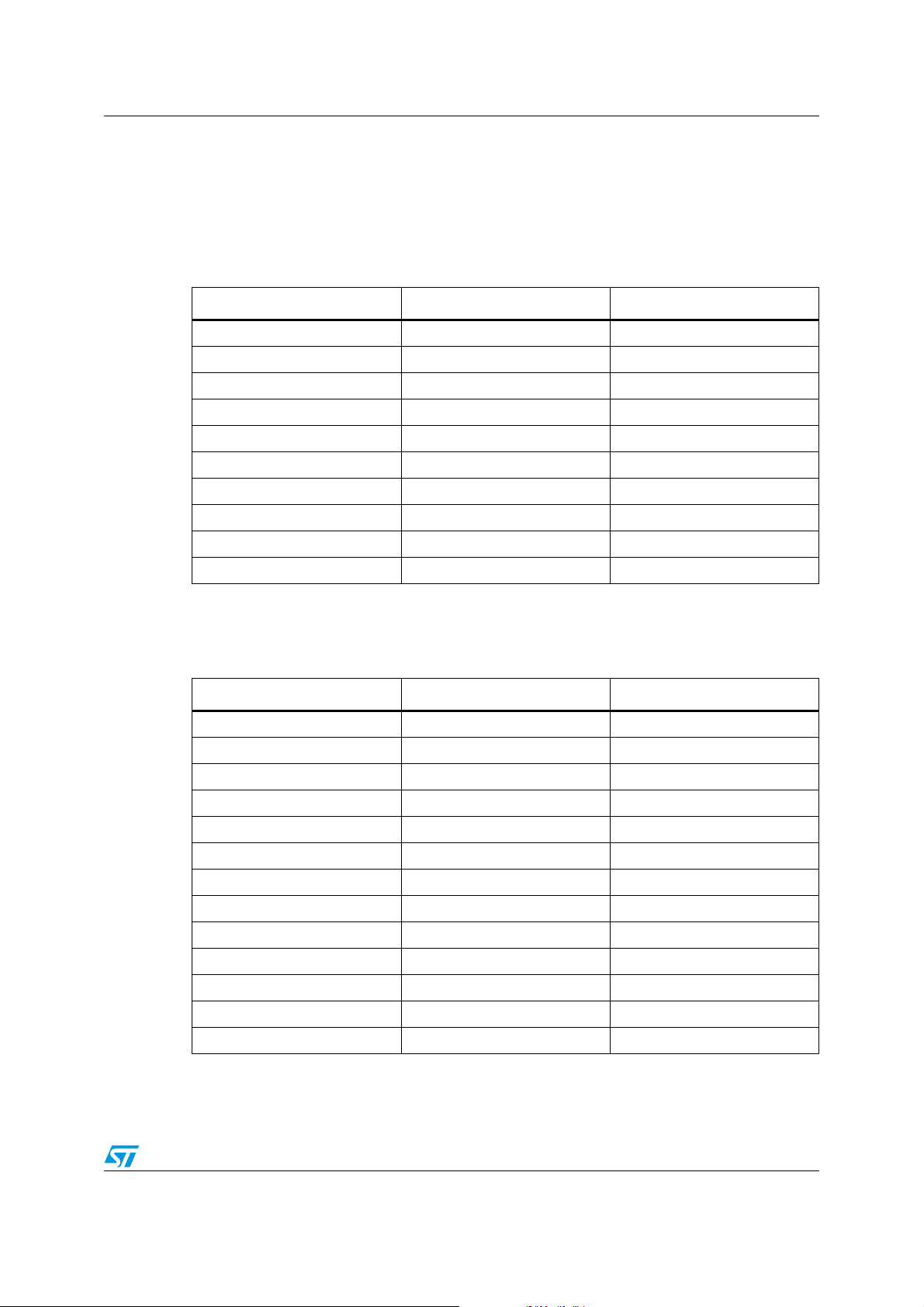
Ta bl e 2 shows the ROM usage (Flash memory) of the bitmap images for each type of
graphic object using IAR 5.5 and high optimization for size:
Table 2. ROM usage of graphic objects
Graphic object type ROM (Flash) Note
Label 0 bytes Totally
Button 2.904 bytes Totally
Checkbox 1.736 bytes Totally
RadioButton 1.736 bytes Totally
ComboBox 4.144 bytes Totally
Switch 2.904 bytes Totally
Icon 0 bytes Totally
Slidebar 944 bytes Totally
Histogram 0 bytes Totally
Graph chart 0 bytes Totally
Ta bl e 3 shows the RAM usage of each type of graphic object:
Table 3. RAM usage of graphic objects
Graphic object type RAM (Heap) Note
Label 101 bytes Each
Button 70 bytes Each
Checkbox 79 bytes Each
RadioButtonGrp 40 bytes Each
RadioOption 48 bytes Each
ComboBoxGrp 90 bytes Each
ComboOption 29 bytes Each
Switch 86 bytes Each
Icon 53 bytes Each
Slidebar 79 bytes Each
Histogram 156 bytes Each
Graph chart 257 bytes Each
Page 162 bytes Each
Doc ID 16918 Rev 5 15/105
Page 16

Multi-input embedded GUI library AN3128
Ta bl e 4 shows the ROM usage (Flash memory) of the font sets:
Table 4. ROM usage of font sets
Font set ROM (Flash) Note
Font 16x24 4.560 bytes Totally
Font 8x12 2.688 bytes Totally
All the graphic objects are allocated dynamically, in a typical application the heap size
should be about 16 KB, and the stack should be about 2 KB.
3.3 Library package
The library was developed supporting Raisonance Ride Kit ARM, IAR the IAR EWARM,
Atollic TrueSTUDIO, Keil MDK-ARM , TASKING VX-toolset for ARM Cortex-M3 and the
related workspace/project files are included in the delivered package.
The “Libraries” folder contains all the subdirectories and files that make up the core of the
library.
Embedded_GUI_HAL contains all files and subdirectories that makes the hardware
abstraction layer (HAL). The developer has to modify only these files if he needs to port the
library to other board with other TSC/LCD/JOYSTICK controller, and set the defined
constant into the file “hw_config.h” contained under the folder
“./Embedded_GUI_Example/inc”:
● inc: sub-folder contains the HAL header files.
– LcdHal.h: HAL layer file; contains all the LCD function prototypes whose
implementation depends on the LCD used. The final user should change this file in
order to re-use this library with other LCDs.
– JoyHal.h: HAL layer file; contains all the joystick function prototypes whose
implementation depends on the joystick controller used by the application. The
user need only change these function implementations in order to re-use this code
with other joystick controllers.
– TscHal.h: HAL layer file; contains all the touchscreen function prototypes whose
implementation depends on the TSC controller used by the application. The user
need only change these function implementations in order to re-use this code with
other TSC controllers.
– touchscreen.h: contains all the function prototypes for the touchscreen firmware
driver.
● src: sub-folder contains the HAL source files.
– LcdHal.c: HAL layer file; contains all the LCD function declarations whose
implementation depends on the LCD used and the MCU (STM32 for this delivery).
The final user should change this file in order to re-use this library with other
LCDs.
– JoyHal.c: HAL layer file; contains all the joystick management function
declarations whose implementation depends on the joystick controller used by the
application. The user only needs to change these functions implementations in
order to re-use this code with other joystick controllers.
16/105 Doc ID 16918 Rev 5
Page 17

AN3128 Multi-input embedded GUI library
– TscHal.c: HAL layer file; contains all the touchscreen management function
declarations whose implementation depends on the TSC controller used by the
application. The user only needs to change these functions implementations in
order to re-use this code with other TSC controllers.
– touchscreen.c: contains all the function declarations for the touchscreen firmware
driver.
Embedded_GUI_Library contains all files and subdirectories that makes the graphic objects
core:
● inc: sub-folder contains the firmware library header files
– cursor.h: contains all the function prototypes and basic structure for the cursor
pointer (arrow header).
– gl_fonts.h: contains all the LCD fonts size definition exported declarations.
– GraphicObject.h: API layer file; contains all the function prototypes for the graphic
objects; the API functions are declared in this file.
– GraphicObjectTypes.h: API layer file; contains all the defined types used by
GraphicObject.c file and related to the graphic objects structures; and the
structure parameters for the LCD, touchscreen, joystick and push button.
– images.h: contains all the Hex dumps of the various images used by the
application.
● src: sub-folder contains the firmware library source files.
– cursor.c: API layer file; contains the exported public API (application programming
interface) and the related private internal functions for the cursor pointer (arrow
header). No direct reference to the hardware and micro firmware library occurs in
this file.
– gl_fonts.c: contains all the LCD font size definitions.
– GraphicObject.c: API layer file; contains the entire exported public API (application
programming interface) and the related private internal functions for the graphic
objects and touchscreen calibration; no direct reference to the hardware and
microcontroller firmware library occurs in this file.
– images.c: contains all the Hex dumps of the various images used by the library
application.
STM32F10x_StdPeriph_Driver, STM32L1xx_StdPeriph_Driver and
STM32F2xx_StdPeriph_Driver sub-folders contain respectively the STM32F10xxxV3.5.0,
STM32L1xxV1.0.0 and STM32F2xxV1.0.0 firmware library files. If the final user wants to
use another microcontroller library version, he can replace the updated library folder and
check the HAL types and the microcontroller library function calls inside the HAL layer files
(TscHal.c, TscHal.h, JoyHal.h, JoyHal.c, LcdHal.c, LcdHal.h).
CMSIS sub-folder contains the STM32F10xxx, STM32L1xx and STM32F2xx CMSIS files:
device peripheral access layer and core peripheral access layer.
The “Project” folder contains all the subdirectories and files that make up the library
demonstration.
● Embedded_GUI_Example sub-folder contains the STM32F10xxx Graphic library
demonstration:
– inc: sub-folder contains the graphic library demonstration header files
– src: sub-folder contains the graphic library demonstration header source files
– EWARM sub-folder contains the IAR EWARM workspace and project files
– RIDE sub-folder contains the Raisonance Ride workspace and project files
Doc ID 16918 Rev 5 17/105
Page 18

Multi-input embedded GUI library AN3128
– MDK-ARM sub-folder contains the Keil MDK-ARM workspace and project files
– TrueSTUDIO sub-folder contains the Atollic TrueSTUDIO workspace and project
files
– TASKING sub-folder contains the TASKING VX-toolset for ARM Cortex-M3
workspace and project files
● Embedded_GUI_Template sub-folder contains the STM32 Graphic library template for
Resource Editor (PC Software) output files:
● inc : sub-folder where to place generated header files from Resource Editor PC
software (uiappuser.h, uiframework.h, uiappuser.h).
● src : sub-folder where to place generated source files from Resource Editor PC
software (uiframework.c, pictures.c, uiappuser.c).
● EWARM sub-folder contains the IAR EWARM workspace and project files
● RIDE sub-folder contains the Raisonance Ride workspace and project files
● MDK-ARM sub-folder contains the Keil MDK-ARM workspace and project files
● TrueSTUDIO sub-folder contains the Atollic TrueSTUDIO workspace and project files
● TASKING sub-folder contains the TASKING VX-toolset for ARM Cortex-M3 workspace
and project files
The “Utilities” folder contains all the subdirectories and files that make up the
STMicroelectronics demonstration board drivers.
● STM32_EVAL sub-folder contains STM32 demonstration board drivers
● PC_SOFTWARE sub-folder contains Resource Editor
The “_htmresc” folder contains all package html page resources.
Figure 4. Firmware library project files
18/105 Doc ID 16918 Rev 5
Page 19

AN3128 Multi-input embedded GUI library
3.4 Library architecture
Library architecture is thought out and developed in two separate layers:
● API layer
● HAL layer
This layer architecture improves the code re-usability splitting the application programming
interface code (fully portable and re-usable) from the hardware abstraction layer code
(hardware dependent and written upon the LCD library).
Figure 5. Firmware library architecture
3.4.1 API layer
The application programming interface layer allows the final application to use the library as
a black-box. The library firmware encapsulation feature and exported API allow a full control
of the LCD and touchscreen without knowing, in-depth, LCD registers and SPI/I
read/write operation steps for the LCD and touchscreen respectively.
● The API layer includes the following files:
– graphicObject.h
– graphicObject.c
– graphicObjectTypes
– cursor.c
– cursor.h
See Section 4.1 for a more detailed description.
3.4.2 HAL layer
The hardware abstraction layer is directly built into the specific LCD firmware library and
allows the build-upon layers, like the API layer, to implement its functions without knowing,
in-depth, the LCD, MCU and touchscreen controller used. This improves the library code re-
2
C
Doc ID 16918 Rev 5 19/105
Page 20

Multi-input embedded GUI library AN3128
usability and guarantees an easy portability on other LCDs, MCUs and touchscreen
controllers.
● The HAL layer includes the following files:
– LcdHal.h
– LcdHal.c
– TscHal.h
– TscHal.c
– JoyHal.h
– JoyHal.c
– Touchscreen.h
– Touchscreen.c
See Section 4.4 for a more detailed description.
20/105 Doc ID 16918 Rev 5
Page 21

AN3128 Multi-input embedded GUI library firmware
4 Multi-input embedded GUI library firmware
This section describes the API and HAL layer implementation. Each library firmware
function is described in detail. An example of how to use API functions is provided. No
example is provided for the HAL function, because the final application should manage the
graphic objects through the API layer functions only, without any direct access to the HAL
functions.
The functions are described in the following format:
Table 5. Function description format
Name Description
Function name The name of the function
Function prototype Prototype declaration of the function
Behavior description Brief explanation of how the function is executed
Input parameter {x} Description of the input parameters
Output parameter {x} Description of the output parameters
Return value Value returned by the function
Required preconditions Requirements before calling the function
Called functions Other library functions called
4.1 Graphic object API functions
The application programming interface layer allows the final application to create pages of
graphic objects and easy use of the STMPE811 touchscreen controller. An OOP approach
is used, so it's possible for the application developer to create and use one or more
instances of a graphic object and work with pages of object without writing the code to
display the graphic objects every time the application changes the focus on another page.
Graphic object structures are seen by the application as objects with encapsulated
properties and methods. In the end, they are advanced structures containing:
● Properties as data fields
● Methods as function pointers
In this way each API function belongs to the related graphic object instance and so, many
graphic objects can be managed without any conflicts.
Every type of graphic object has a pre-event function that provides the process to change its
visualization on the screen and the internal status of the object; for example in a ComboBox,
when the user hits the “Down Arrow” the pre-event function changes the image associated
showing the one associated to Image2_PTR for a few moments, and sets the next option in
the list as active. This function is predefined for each type of object and very useful in order
to minimize the developer workload. In this way, the developer need only place graphic
objects on the screen page and write a function event that is called after the pre-event
function, when a touch/click event occurs between the object coordinates area.
Doc ID 16918 Rev 5 21/105
Page 22

Multi-input embedded GUI library firmware AN3128
The library exports the following public API global functions in order to create the graphic
objects type structure instance and set/get the relative properties:
● NewLabel function
● NewButton function
● NewSwitch function
● NewCheckbox function
● NewIcon function
● NewRadioButtonGrp function
● AddRadioOption function
● NewSlidebar function
● NewHistogram function
● NewGraphChart function
● NewComboBoxGrp function
● AddComboOption function
● Create_PageObj function
● AddPageControlObj function
● DestroyPageControl function
● DestroyPage function
● Set_Label function
● Get_Label function
● Get_SlidebarValue function
● SetGraphChartPoints function
● SetHistogramPoints function
● GetObjStatus function
● GetComboOptionActive function
● ResetComboOptionActive function
● GetComboOptionLabel function
● SetComboOptionLabel function
● SetIconImage function
● ShowPage function
● RefreshPage function
● RefreshPageControl function
● ChangePage function.
22/105 Doc ID 16918 Rev 5
Page 23

AN3128 Multi-input embedded GUI library firmware
4.1.1 NewLabel API global function
Ta bl e 6 describes the NewLabel function:
Table 6. NewLabel API function
Name Description
Function name NewLabel
Function prototype
Behavior description Create and initialize a new Label Object (a C structure)
Input parameter {x}
Output parameter {x} None
Return value The created object pointer or null if the object cannot be created
Required preconditions None
GL_PageControls_TypeDef* NewLabel (char* oName, char* Label,
GL_Direction_direction, GL vu8 FontSize, GL vuint16_t color)
oName: object name
Label: text on a Label Object
Direction: the direction to follow printing the Label
FontSize: the size of the font: FONT_BIG or FONT_SMALL
Color: color of the Label text
Called functions No API/HAL layer functions
Example:
/* Declares and initiates a Page Object */
GL_Page_TypeDef page1;
Create_PageObj( &page1 );
/* Declares and initiates a Label Object and add it with specified coordinates to a
Page Object */
GL_PageControls_TypeDef* pageLabel = NewLabel("pageLabel","Graphic Library",
GL_HORIZONTAL, GL_FONT_BIG, GL_Blue);
AddPageControlObj((uint16_t)((LCD_Width/11)*9),(uint8_t)(LCD_Height/11),pageLabel,
&page1);
Once a Label Object instance is created using the NewLabel function, the Label Object itself
provides all its features through its internal function pointers.
Figure 14, 15, 16, show, in detail, the Label Object properties and methods which the final
application can use to interact with.
Doc ID 16918 Rev 5 23/105
Page 24

Multi-input embedded GUI library firmware AN3128
4.1.2 NewButton API global function
The button object is the most used and its graphical look changes temporarily during the
interaction between the touchscreen or the joystick. In fact there are two looks for the button
as well as for the majority of the others objects.
When the button is pressed, its “graphical look” changes for a few moments and then
returns to the starting aspect.
Inside the button, it's possible to insert a text Label, by which the button width itself depends.
The library automatically fits the width and places the text in the center.
Figure 6. Button graphical layout
Ta bl e 7 describes the NewButton function:
Table 7. NewButton API function
Name Description
Function name NewButton
Function prototype
Behavior description Create and initialize a new button object (a C structure)
Input parameter {x}
Output parameter {x} None
Return value The created object pointer or null if the object cannot be created
Required preconditions None
Called functions No API/HAL layer functions
GL_PageControls_TypeDef* NewButton (char* oName, char* Label,
void* (*pEventHandler)(void))
oName: object name
Label: Label on button
pEventHandler: pointer to function associated to its touch event
Example:
/* Declares and initiates a Page Object */
GL_Page_TypeDef page1;
Create_PageObj( &page1 );
/* Declares & initiates a Button Object and add it with specified coordinates to a
Page Object */
GL_PageControls_TypeDef* TestBtn = NewButton("TestBtn", "Test Button", TestBtnFunc);
AddPageControlObj((uint16_t)((LCD_Width/10)*6), (uint8_t)((LCD_Height/9)*4),
TestBtn, &page1);
Once a button object instance is created using the NewButton function, the button object
itself provides all its features through its internal function pointers.
24/105 Doc ID 16918 Rev 5
Page 25

AN3128 Multi-input embedded GUI library firmware
Figure 14, 15, 16, show, in detail, the button object properties and methods which the final
application can use to interact with.
4.1.3 NewCheckbox API global function
The checkbox object follows a Boolean principle so its value can be defined in a binary way
(0/1).
A typical example of this kind of object could be enable/disable a variable concerning a
specified feature/option.
Figure 7. Checkbox graphical layout
Ta bl e 8 describes the NewCheckbox function:
Table 8. NewCheckbox API function
Name Description
Function name NewCheckbox
Function prototype
Behavior description Create and initialize a new Label Object (a C structure)
Input parameter {x}
Output parameter {x} None
Return value The created object pointer or null if the object cannot be created
GL_PageControls_TypeDef* NewCheckbox (char* oName, char* Label,
void* (*pEventHandler)(void))
oName: object name
Label: Label for the checkbox
pEventHandler: pointer to function associated to its touch event
Required preconditions None
Called functions No API/HAL layer functions
Example
/* Declares and initiates a Page Object */
GL_Page_TypeDef page1;
Create_PageObj( &page1 );
/* Declares and initiates a Checkbox Object and add it with specified coordinates to
a Page Object */
GL_PageControls_TypeDef* CheckBox = NewCheckbox("CheckBox", "Enable", CheckboxFunc);
AddPageControlObj((uint16_t)((LCD_Width/10)*7),(uint8_t)((LCD_Height/9)*4),CheckBox,
&page1);
Once a checkbox object instance is created using the NewCheckbox function, the checkbox
object itself provides all its features through its internal function pointers.
Figure 14, 15, 16, show, in detail, the Checkbox object properties and methods which the
final application can use to interact with.
Doc ID 16918 Rev 5 25/105
Page 26

Multi-input embedded GUI library firmware AN3128
4.1.4 NewSwitch API global function
The switch object or SwitchButton is very similar to the button object and actually contains
all its features, the only difference being that when this object is stimulated through the
touchscreen or the joystick, its state, and then its graphical look, change permanently until a
new press event.
The most obvious function of this object is to change the status of a Boolean/Binary variable
(0/1) and so enable/disable something.
Figure 8. Switch graphical layout
Ta bl e 9 describes the NewSwitch function:
Table 9. NewSwitch API function
Name Description
Function name NewSwitch
Function prototype
Behavior description Create and initialize a new Label Object (a C structure)
Input parameter {x}
Output parameter {x} None
Return value The created object pointer or null if the object cannot be created
Required preconditions None
Called functions No API/HAL layer functions
GL_PageControls_TypeDef* NewSwitch (char* oName, char* Label_1,
char* Label_2, void* (*pEventHandler)(void))
oName: object name
Label_1: Label on not clicked switch button
Label_2: Label on clicked switch button
pEventHandler: pointer to function associated to its touch event
Example
/* Declares and initiates a Page Object */
GL_Page_TypeDef page1;
Create_PageObj( &page1 );
/* Declares and initiates a Switch Object and add it with specified coordinates to a
Page Object */
GL_PageControls_TypeDef* EnDisBtn = NewSwitch("EnDisBtn","Enable","Disable",MyFunc);
AddPageControlObj((uint16_t)((LCD_Width/10)*6),(uint8_t)((LCD_Height/9)*4),EnDisBtn,
&page1);
Once a switch object instance is created using the NewSwitch function, the switch object
itself provides all its features through its internal function pointers.
Figure 14, 15, 16, show, in detail, the switch object properties and methods which the final
application can use to interact with.
26/105 Doc ID 16918 Rev 5
Page 27

AN3128 Multi-input embedded GUI library firmware
4.1.5 NewIcon API global function
This object allows the user to show an arbitrary image on the LCD, stored in the Flash
memory of the MCU, and associate the press event of the image itself through the
touchscreen or the joystick.
Ta bl e 1 0 describes the NewIcon function:
Table 10. NewIcon API function
Name Description
Function name NewIcon
GL_PageControls_TypeDef* NewIcon (char* oName, GL_uint8_t*
Function prototype
Behavior description Create and initialize a new icon object (a C structure)
Input parameter {x}
Output parameter {x} None
Return value The created object pointer or null if the object cannot be created
Image_PTR, GL_uint16_t Width, GL_uint8_t Height, void*
(*pEventHandler)(void))
oName: object name
Image_PTR: icon image pointer
Width: image width
Height: image height
pEventHandler: pointer to function associated to its touch event
Required preconditions None
Called functions No API/HAL layer functions
Example:
/* Declares and initiates a Page Object */
GL_Page_TypeDef page1;
Create_PageObj( &page1 );
/* Declare and initiate a Icon Object and add it with specified coordinates to a Page
Object */
GL_PageControls_TypeDef* MyIcon = NewIcon ("MyIcon", NULL, 90, 90, NullFunc);
AddPageControlObj( (uint16_t)((LCD_Width/2)+45),(uint8_t)((LCD_Height/2)+45),MyIcon,
&page1 );
Once an icon object instance is created using the icon function, the icon object itself
provides all its features through its internal function pointers.
Figure 14, 15, 16, show, in detail, the icon object properties and methods which the final
application can use to interact with.
Doc ID 16918 Rev 5 27/105
Page 28

Multi-input embedded GUI library firmware AN3128
4.1.6 NewRadioButtonGrp API global function
The radio button (sometimes called the option button) is a special kind of button that allows
the user to choose only one of a predefined set of alternatives. Its name derives from the old
car radio, where this button was used to select the preset stations. The major difference with
the ordinary button is that the radio buttons are arranged in groups where the group acts as
a big switchboard. In a group, only one radio button must be selected at most. Then, if in a
group, the first radio button is in the selected state, and suddenly the second radio button is
pressed, the first one must be immediately released going back to the normal state, and the
second passes to the selected state.
Figure 9. Radio button graphical layout
Ta bl e 1 1 describes the NewRadioButtonGrp function:
Table 11. NewRadioButtonGrp API function
Name Description
Function name NewRadioButtonGrp
Function prototype GL_RadioButtonGrp_TypeDef* NewRadioButtonGrp (char* oName)
Behavior description Create and initialize a new RadioButtonGrp object (a C structure)
Input parameter {x} oName: object name
Output parameter {x} None
Return value The created object pointer or null if the object cannot be created
Required preconditions None
Called functions No API/HAL layer functions
Example:
/* Declares and initiates a RadioButtonGrp Object */
GL_RadioButtonGrp_TypeDef* RadioButtonGrp = NewRadioButtonGrp("RadioButtonGrp");
4.1.7 AddRadioOption API global function
Ta bl e 1 2 describes the AddRadioOption function:
Table 12. AddRadioOption API function
Name Description
Function name AddRadioOption
GL_PageControls_TypeDef* AddRadioOption
Function prototype
Behavior description Create and initialize a new Label Object (a C structure)
28/105 Doc ID 16918 Rev 5
(GL_RadioButtonGrp_TypeDef* pThis, char* Label, void*
(*pEventHandler)(void))
Page 29

AN3128 Multi-input embedded GUI library firmware
Table 12. AddRadioOption API function (continued)
Name Description
GL_RadioButtonGrp_TypeDef*: pThis
Input parameter {x}
Label: Label for RadioButton option
pEventHandler: pointer to function associated to its touch event
Output parameter {x} None
Return value The created object pointer or null if the object cannot be created
Required preconditions NewRadioButtonGrp must have been called before
Called functions No API/HAL layer functions
Example:
/* Declares and initiates a Page Object */
GL_Page_TypeDef page1;
Create_PageObj( &page1 );
/* Declares and initiates a RadioButton Group Object */
GL_RadioButtonGrp_TypeDef* RButtonGrp = NewRadioButtonGrp("RButtonGrp");
/* Declare/initiate a RadioOption Object and add it with specified coordinates to a
Page Object */
GL_PageControls_TypeDef* ROption_a = RADIO_BUTTON_ADD(RButtonGrp,"Option1",RBtnFunc1);
GL_PageControls_TypeDef
AddPageControlObj((uint16_t)(LCD_Width/2),(uint8_t)((LCD_Height/9)*3),ROption_a,
&page1);
AddPageControlObj((uint16_t)(LCD_Width/2),(uint8_t)((LCD_Height/9)*4),ROption_b,
&page1);
* ROption_b = RADIO_BUTTON_ADD(RButtonGrp,"Option2",RBtnFunc2);
Note: As can be seen from the code above, to simplify the adding of a radio option the user should
not directly use the function “AddRadioOption()”, but must use the following macro instead:
#define RADIO_BUTTON_ADD(RadioButtonGrpName, Label, Function) \
RadioButtonGrpName->AddRadioOption(RadioButtonGrpName,Label,Function);
Once a RadioOption object instance is created using the AddRadioOption function, the
RadioOption object itself provides all its features through its internal function pointers.
Figure 14, 15, 16, show, in detail, the RadioOption object properties and methods which the
final application can use to interact with.
4.1.8 NewComboBoxGrp API global function
This kind of object allows the user to choose an option from a list of alternatives that can be
scrolled by selecting the up/down arrows.
Figure 10. Combobox graphical layout
Doc ID 16918 Rev 5 29/105
Page 30

Multi-input embedded GUI library firmware AN3128
Ta bl e 1 3 describes the NewComboBoxGrp function:
Table 13. NewComboBoxGrp API function
Name Description
Function name NewComboBoxGrp
Function prototype GL_PageControls_TypeDef* NewComboBoxGrp (char* oName)
Behavior description Create and initialize a new
Input parameter {x} oName: object name
Output parameter {x} None
Return value The created object pointer or null if the object cannot be created
Required preconditions None
Called functions No API/HAL layer functions
ComboBoxGrp object (a C structure)
Example:
/* Declares and initiates a Page Object */
GL_Page_TypeDef page1;
Create_PageObj( &page1 );
/* Declares and initiates a ComboBoxGroup Object and add it with specified
coordinates to a Page Object */
GL_PageControls_TypeDef* MyComboGrp = NewComboBoxGrp("MyComboGrp");
AddPageControlObj((uint16_t)((LCD_Width/10)*8),(uint8_t)(LCD_Height/2),MyComboGrp,
&page1);
Once a ComboBoxGrp object instance is created using the NewComboBoxGrp function, the
ComboBoxGrp object itself provides all its features through its internal function pointers.
Figure 14, 15, 16, show, in detail, the ComboBoxGrp object properties and methods which
the final application can use to interact with.
4.1.9 AddComboOption API global function
Ta bl e 1 4 describes the AddComboOption function:
Table 14. AddComboOption API function
Name Description
Function name AddComboOption
Function prototype
Behavior description Create and initialize a new ComboBoxOption object (a C structure)
Input parameter {x}
Output parameter {x} None
Return value GL_OK if successful, GL_ERROR otherwise
30/105 Doc ID 16918 Rev 5
GL_ErrStatus AddComboOption (GL_ComboBoxGrp_TypeDef* pThis,
char* Label, void* (*pEventHandler)(void))
GL_ComboBoxGrp_TypeDef*: pThis
Label: Label for RadioButton option
pEventHandler: pointer to function associated to its touch event
Page 31

AN3128 Multi-input embedded GUI library firmware
Table 14. AddComboOption API function (continued)
Name Description
Required preconditions NewComboBoxGrp must have been called before
Called functions No API/HAL layer functions
Example:
GL_ErrStatus errStatus;
/* Declares and initiates a Page Object */
GL_Page_TypeDef page1;
Create_PageObj( &page1 );
/* Declare and initiate a ComboBoxGroup with its ComboOptions Object and add it with
specified coordinates to a Page Object */
GL
_PageControls_TypeDef* MyComboGrp = NewComboBoxGrp("MyComboGrp");
AddComboOption (MyComboGrp ->objPTR, "Option1", MyComboboxFunc);
AddComboOption (MyComboGrp ->objPTR, "Option2", MyComboboxFunc);
AddComboOption (MyComboGrp ->objPTR, "Option3", MyComboboxFunc);
AddComboOption (MyComboGrp ->objPTR, "Option4", MyComboboxFunc);
AddPageControlObj((uint16_t)((LCD_Width/10)*8),(uint8_t)(LCD_Height/2),MyComboGrp,
&page1);
Once a ComboBoxGrp object and its combo option instances are created using the
NewComboBoxGrp and AddComboOption functions, ComboBoxGrp and combo option
objects themselves provide all their features through their internal function pointers.
Figure 14, 15, 16, show, in detail, the ComboBoxOption object properties and methods
which the final application can use to interact with.
4.1.10 NewSlidebar API global function
This kind of object is composed of a rectangular shaped 3D image and a thin cursor that can
be moved using the joystick or touchscreen pressing the cursor itself laterally. The variance
is established in a percentage from 0 to 100, and the minimum step is fixed at 5%.
A typical example of the application of this object could be the volume variation of the audio
output in an MP3 player.
It is possible to read the current value of the cursor position through the function
“Get_SlidebarValue” defined in the following pages, therefore easily integrating such an
object in the application.
The slidebar can be chosen to be printed horizontally or vertically, as shown in Figure 11.
Figure 11. Slidebar graphical object
Doc ID 16918 Rev 5 31/105
Page 32

Multi-input embedded GUI library firmware AN3128
Ta bl e 1 5 describes the NewSlidebar function:
Table 15. NewSlidebar API function
Name Description
Function name NewSlidebar
Function prototype
Behavior description Create and initialize a new slidebar object (a C structure)
Input parameter {x}
Output parameter {x} None
Return value The created object pointer or null if the object cannot be created
Required preconditions None
Called functions No API/HAL layer functions
GL_PageControls_TypeDef* NewSlidebar (char* oName, char* Label,
GL_Direction, void* (*pEventHandler)(void))
oName: object name
Label: Label for slidebar meaning
direction: the printing orientation. The parameters can be GL_Vertical or
GL_Horizontal
pEventHandler: pointer to function associated to its touch event
Example:
/* Declares and initiates a Page Object */
GL_Page_TypeDef page1;
Create_PageObj( &page1 );
/* Declares and initiates a Slidebar Object and add it with specified coordinates to
a Page Object */
GL_PageControls_TypeDef* MySlidebar = NewSlidebar("MySlidebar", "Volume",
GL_Horizontal, MySlidebarFunc);
AddPageControlObj((uint16_t)((LCD_Width/10)*7),(uint8_t)(LCD_Height/2),MySlidebar,
&page1);
Once a slidebar object instance is created using the NewSlidebar function, the slidebar
object itself provides all its features through its internal function pointers.
Figure 14, 15, 16, show, in detail, the slidebar object properties and methods which the final
application can use to interact with.
32/105 Doc ID 16918 Rev 5
Page 33

AN3128 Multi-input embedded GUI library firmware
4.1.11 NewHistogram API global function
This kind of object is composed of two axes (X & Y) with the relative values printed to the
side, and a certain number of blue columns representing the real distribution of respective
values. The values are saved in a vector of decimal numbers.
A typical example of the application of this object may be reading the distribution of
measured values concerning changing data.
It is possible to change the values of the vectors through the function “SetHistogramPoints”
defined in the following pages, therefore easily integrating such an object into the
application.
Figure 12. Histogram graphical object
Ta bl e 1 6 describes the NewHistogram function:
Table 16. NewHistogram API function
Name Description
Function name NewHistogram
Function prototype
Behavior description Create and initialize a new histogram object (a C structure)
Input parameter {x}
Output parameter {x} None
Return value The created object pointer or null if the object cannot be created
GL_PageControls_TypeDef* NewHistogram (char* oName, char* LabelX,
char* LabelY, int16_t data_points[], GL_uint8_t n_points);
oName: object Name
LabelX: Label for the X axis
LabelY: Label for the Y axis
data_points[]: the array of points to be plotted on the LCD pointer to
function associated to its touch event
n_points: number of points to be plotted
Doc ID 16918 Rev 5 33/105
Page 34

Multi-input embedded GUI library firmware AN3128
Table 16. NewHistogram API function (continued)
Name Description
Required preconditions None
Called functions No API/HAL layer functions
Example:
/* Declares and initiates a Page Object */
GL_Page_TypeDef page1;
Create_PageObj( &page1 );
/* Declares and initiates a Histogram Object and add it with specified coordinates to
a Page Object */
int16_tMyHistPoints[24];
MyHistPoints = {1,2,3,4,5,6,7,8,9,10,11,12,13,14,15,16,17,18,19,20,21,22,23,24};
GL_PageControls_TypeDef* MyHistogram = NewHistogram("MyHistogram", "Hours", "Wh",
MyHistPoints, 24 );
AddPageControlObj( 0, 0, MyHistogram, &page1 );
Once a histogram object instance is created using the NewHistogram function, the
histogram object itself provides all its features through its internal function pointers.
Figure 14, 15, 16, show, in detail, the histogram object properties and methods which the
final application can use to interact with.
34/105 Doc ID 16918 Rev 5
Page 35

AN3128 Multi-input embedded GUI library firmware
4.1.12 NewGraphChart API global function
This kind of object is made up of two axes (X and Y) with the relative values printed to the
side, and a certain number of blue columns representing the real distribution of respective
values. The values are saved in a vector of decimal numbers.
A typical example of the application of this object may be reading the distribution of
measured values concerning changing data.
It is possible to change the values of the vectors through the function “SetGraphChartPoints”
defined in the following pages, therefore easily integrating such an object into the
application.
Figure 13. GraphChart graphical object
Ta bl e 1 7 describes the NewGraphChart function:
Table 17. NewGraphChart API function
Function name NewGraphChart
GL_PageControls_TypeDef* NewGraphChart (char* oName, char* LabelX,
Function prototype
Behavior description Create and initialize a new GraphChart object (a C structure)
Input parameter {x}
Output parameter {x} None
char* LabelY, int16_tdata_points[], GL_uint8_t n_points, GL_bool
Background)
oName: object Name
LabelX: Label for the X axis
LabelY: Label for the Y axis
data_points[]: the array of points to be plotted on the LCD pointer to
function associated to its touch event
n_points: number of points to be plotted
Background: select if black background has to be used. This parameter can
be GL_TRUE or GL_FALSE
Doc ID 16918 Rev 5 35/105
Page 36

Multi-input embedded GUI library firmware AN3128
Table 17. NewGraphChart API function (continued)
Function name NewGraphChart
Return value The created object pointer or null if the object cannot be created
Required preconditions None
Called functions No API/HAL layer functions
Example:
/* Declares and initiates a Page Object */
GL_Page_TypeDef page1;
Create_PageObj( &page1 );
/* Declares & initiates a GraphChart Object and add it with specified coordinates to
a Page Object */
int16_tMyChartPoints[24];
MyChartPoints = {1,2,3,4,5,6,7,8,9,10,11,12,13,14,15,16,17,18,19,20,21,22,23,24};
GL_PageControls_TypeDef* MyGraphChart = NewGraphChart("MyGraphChart", "Hours", "Wh",
MyChartPoints, 24);
AddPageControlObj( 0, 0, MyGraphChart, &page1 );
Once a GraphChart object instance is created using the NewGraphChart function, the
GraphChart object itself provides all its features through its internal function pointers.
Figure 14, 15, 16, show, in detail, the GraphChart object properties and methods which the
final application can use to interact with.
4.1.13 AddPageControlObj API global function
Ta bl e 1 8 describes the AddPageControlObj function:
Table 18. AddPageControlObj API function
Name Description
Function name AddPageControlObj
Function prototype
Behavior description Add a new control object to the page
Input parameter {x}
Output parameter {x} None
Return value GL_OK if successful, GL_ERROR otherwise
Required preconditions
GL_ErrStatus AddPageControlObj (GL_uint16_t PosX, GL_uint8_t PosY,
GL_PageControls_TypeDef* objPTR, GL_Page_TypeDef* pagePTR)
PosX & PosY: max and min coordinates for X and Y axis
*objPTR: pointer to object structure
*pagePTR: pointer to page structure
NewXXX must have been called before, where XXX represents a kind of
graphical object
Called functions No API/HAL layer functions
The values of PosX and PosY parameters represent the coordinates of the top-left corner of
the object according to the origin coordinates placed in the top-right corner of the LCD.
36/105 Doc ID 16918 Rev 5
Page 37

AN3128 Multi-input embedded GUI library firmware
Example:
GL_ErrStatus errStatus;
/* Declares and initiates a Page Object */
GL_Page_TypeDef page1;
Create_PageObj( &page1 );
. . . . . .
/* Adding an object with specified coordinates to a Page Object */
errStatus =
AddPageControlObj((uint16_t)((LCD_Width/10)*7.5),(uint8_t)(LCD_Height/2),
MyGraphicObject, &page1);
Once a PageControl object instance is created using the AddPageControlObj function, the
PageControl object itself provides all its features through its internal function pointers.
Figure 14, 15, 16, show, in detail, the PageControl object properties and methods which the
final application can use to interact with.
4.1.14 DestroyPageControl API global function
Ta bl e 1 9 describes the DestroyPageControl function:
Table 19. DestroyPageControl API function
Name Description
Function name DestroyPageControl
Function prototype
GL_ErrStatus DestroyPageControl (GL_Page_TypeDef* pPage, char*
objName)
Behavior description Free the allocated memory for a PageControl object
Input parameter {x}
*pPage: pointer to page structure
objName: name of the object
Output parameter {x} None
Return value GL_OK if successful, GL_ERROR otherwise
Required preconditions
NewXXX must have been called before, where XXX represents a kind of
graphical object
Called functions No API/HAL layer functions
Example:
GL_ErrStatus errStatus;
/* Declares and initiates a Page Object */
GL_Page_TypeDef page1;
Create_PageObj( &page1 );
...
/* Adding an object with specified coordinates to a PageControl Object */
errStatus = AddPageControlObj((
MyGraphObj,&page1);
/* De-allocate a Page Object */
DestroyPageControl(page1, "MyGraphicObject");
uint16_t)(LCD_Width/2),(uint8_t)(LCD_Height/2),
Once a PageControl object instance is created, it can be destroyed at any time using the
DestroyPageControl function, and its pointer is set to NULL.
Doc ID 16918 Rev 5 37/105
Page 38

Multi-input embedded GUI library firmware AN3128
4.1.15 DestroyPage API global function
Ta bl e 2 0 describes the DestroyPage function:
Table 20. DestroyPage API function
Name Description
Function name DestroyPage
Function prototype GL_ErrStatus DestroyPage (GL_Page_TypeDef * pPage)
Behavior description
Input parameter {x} *pPage: pointer to page structure
Output parameter {x} None
Return value GL_OK if successful, GL_ERROR otherwise
Required preconditions
Called functions No API/HAL layer functions
Free the allocated memory for all the PageControl objects belonging to a
page
NewXXX must have been called before, where XXX represents a kind of
graphical object
Example:
GL_ErrStatus errStatus;
/* Declares and initiates a Page Object */
GL_Page_TypeDef page1;
Create_PageObj( &page1 );
. . . . . .
/* Adding an object with specified coordinates to a PageControl */
errStatus = AddPageControlObj( (uint16_t)(LCD_Width/2), (uint8_t)(LCD_Height/2),
MyGraphicObject, &page1);
/* De-allocate all the Object belonging to a Page */
DestroyPage(&page1);
Once a page object instance is created, it can be destroyed at any time using the
DestroyPage function, and its pointer is set to NULL.
4.1.16 Set_Label API global function
Ta bl e 2 1 describes the Set_Label function:
Table 21. Set_Label API function
Name Description
Function name Set_Label
Function prototype
Behavior description Modify the Label in a Label Object
38/105 Doc ID 16918 Rev 5
GL_ErrStatus Set_Label (GL_Page_TypeDef* pPage, char* objName, char*
Label)
Page 39

AN3128 Multi-input embedded GUI library firmware
Table 21. Set_Label API function (continued)
Name Description
pPage: pointer to page structure
Input parameter {x}
objName: name of the object
Label: text on a Label Object
Output parameter {x} None
Return value GL_OK if successful, GL_ERROR otherwise
Required preconditions None
Called functions No API/HAL layer functions
Example:
/* Declares and initiates a Page Object */
GL_Page_TypeDef page1;
Create_PageObj( &page1 );
/* Declares and initiates a Label Object and add it with specified coordinates to a
Page Object */
GL_PageControls_TypeDef* pageLabel = NewLabel("pageLabel", "Graphic Library",
GL_HORIZONTAL, GL_FONT_BIG, GL_Blue);
AddPageControlObj((uint16_t)((LCD_Width/11)*9), (uint8_t)(LCD_Height/11), pageLabel,
&page1);
/* Modify the label in a "Label Object" */
Set_Label(&page1, "pageLabel", "Graphic Library New")
Figure 14, 15, 16, show, in detail, the Label Object properties and methods which the final
application can use to interact with.
4.1.17 Get_Label API global function
Ta bl e 2 2 describes the Get_Label function:
Table 22. Get_Label API function
Name Description
Function name Get_Label
Function prototype
Behavior description Return the Label of a Label Object
Input parameter {x}
Output parameter {x} Label: this is the variable where the Label of a Label Object is copied into
Return value GL_OK if successful, GL_ERROR otherwise
Required preconditions None
Called functions No API/HAL layer functions
GL_ErrStatus Get_Label (GL_Page_TypeDef* pPage, char* objName,
char* Label)
*pPage: pointer to page structure
objName: name of the object
Doc ID 16918 Rev 5 39/105
Page 40
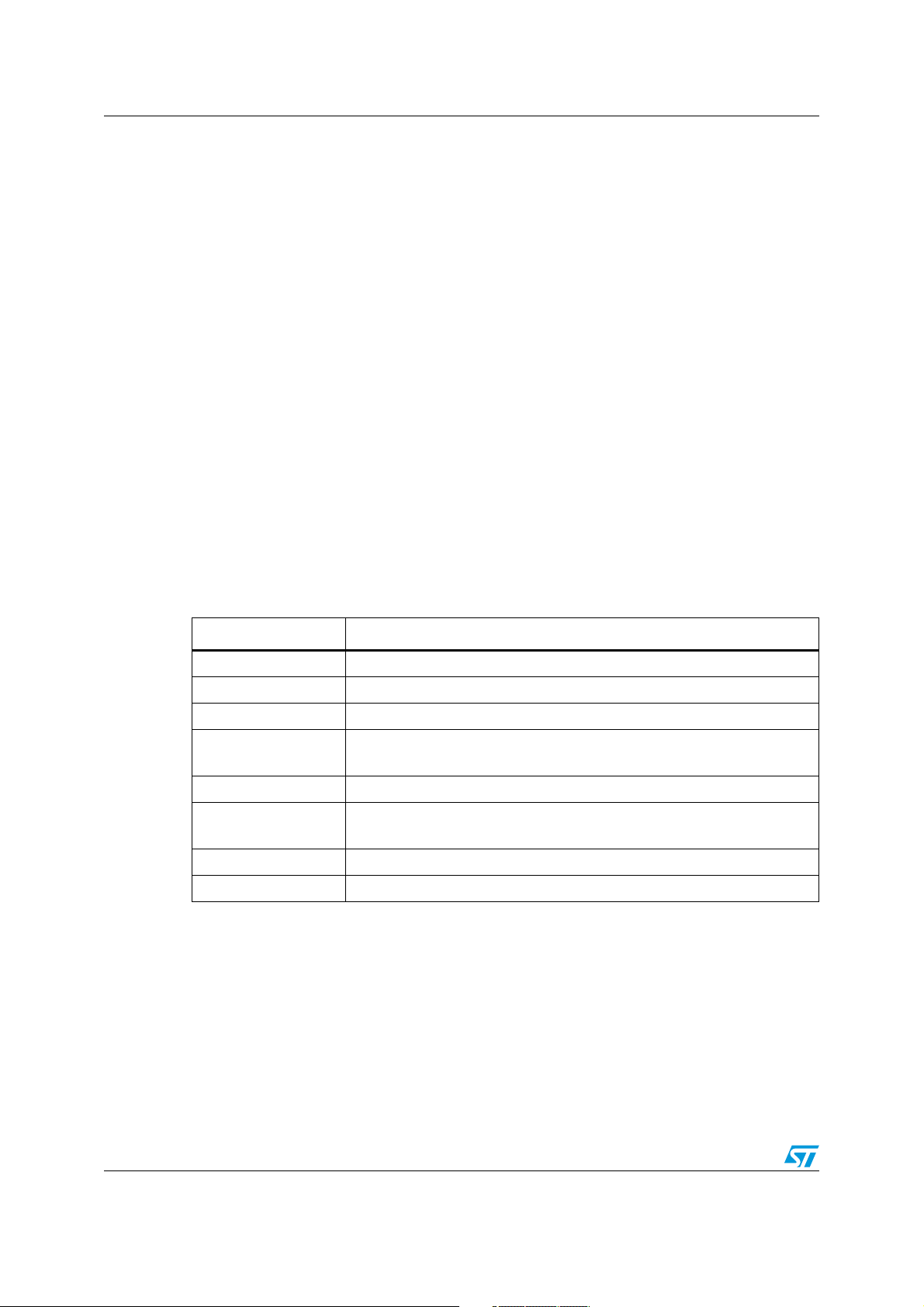
Multi-input embedded GUI library firmware AN3128
Example:
/* Declares and initiates a Page Object */
GL_Page_TypeDef page1;
Create_PageObj( &page1 );
/* Declares and initiates a Label Object and add it with specified coordinates to a
Page Object */
GL_PageControls_TypeDef* pageLabel = NewLabel("pageLabel", "Graphic Library",
GL_HORIZONTAL, GL_FONT_BIG, GL_Blue);
AddPageControlObj((uint16_t)((LCD_Width/11)*9),(uint8_t)(LCD_Height/11),pageLabel,
&page1);
/* Modify the label in a "Label Object" */
Set_Label(&page1, "pageLabel", "Graphic Library New")
/* Get the label in a "Label Object" */
Char* label;
Get_Label(&page1, "pageLabel", label)
Figure 14, 15, 16, show, in detail, the Label Object properties and methods which the final
application can use to interact with.
4.1.18 GetComboOptionLabel API global function
Ta bl e 2 3 describes the GetComboOptionLabel function:
Table 23. GetComboOptionLabel API function
Name Description
Function name GetComboOptionLabel
Function prototype char* GetComboOptionLabel(GL_Page_TypeDef* pPage, char* objName)
Behavior description Return the active combo option Label
Input parameter {x}
*pPage: pointer to page structure
objName: name of the object
Output parameter {x} None
Return value
char* Label: the active combo option Label if the object was found
GL_NULL: if the object was not found
Required preconditions None
Called functions No API/HAL layer functions
Example:
/* Declares and initiates a Page Object */
GL_Page_TypeDef page1;
Create_PageObj( &page1 );
/* Declares and initiates a Label Object and add it with specified coordinates to a
Page Object */
AddPageControlObj((uint16_t)((LCD_Width/11)*9),(uint8_t)(LCD_Height/11),pageLabel,
&page1);
/* Declares and initiates a Combobox object */
GL_PageControls_TypeDef* ComboBoxGrp1 = NewComboBoxGrp("ComboBoxGrp1");
40/105 Doc ID 16918 Rev 5
Page 41

AN3128 Multi-input embedded GUI library firmware
AddComboOption (ComboBoxGrp1->objPTR, "Option1", ComboboxFunc);
AddComboOption (ComboBoxGrp1->objPTR, "Option2", ComboboxFunc);
AddComboOption (ComboBoxGrp1->objPTR, "Option3", ComboboxFunc);
AddPageControlObj((uint16_t)((LCD_Width/10)*7),(uint16_t)(LCD_Height/2),
&page1);
/* Modify the label in a "Label Object by the active combobox option label" */
Set_Label( &page1, "pageLabel", GetComboOptionLabel(&page1, "ComboBoxGrp1") );
ComboBoxGrp1,
Figure 14, 15, 16, show, in detail, the Combobox object properties and methods which the
final application can use to interact with.
4.1.19 SetComboOptionLabel API global function
Ta bl e 2 4 describes the SetComboOptionLabel function:
Table 24. SetComboOptionLabel API function
Name Description
Function name SetComboOptionLabel
Function prototype
GL_ErrStatus SetComboOptionLabel(GL_Page_TypeDef* pPage, char*
objName, char* Label)
Behavior description Set the Label for the active ComboOption
*pPage: pointer to page structure
Input parameter {x}
objName: name of the object
Label: new Label for the active ComboOption object
Output parameter {x} None
Return value GL_OK if successful, GL_ERROR otherwise
Required
preconditions
None
Called functions No API/HAL layer functions
Example:
/* Declares and initiates a Page Object */
GL_Page_TypeDef page1;
Create_PageObj( &page1 );
/* Declares and initiates a Label Object and add it with specified coordinates to a
Page Object */
GL_PageControls_TypeDef* pageLabel = NewLabel("pageLabel", "Graphic Library",
GL_HORIZONTAL, GL_FONT_BIG, GL_Blue);
AddPageControlObj((uint16_t)((LCD_Width/11)*9),(uint8_t)(LCD_Height/11),pageLabel,
&page1);
/* Declares and initiates a Combobox object */
GL_PageControls_TypeDef* ComboBoxGrp1 = NewComboBoxGrp("ComboBoxGrp1");
AddComboOption (ComboBoxGrp1->objPTR, "Option1", ComboboxFunc);
AddComboOption (ComboBoxGrp1->objPTR, "Option2", ComboboxFunc);
AddComboOption (ComboBoxGrp1->objPTR, "Option3", ComboboxFunc);
AddPageControlObj((uint16_t)((LCD_Width/10)*7),(uint16_t)(LCD_Height/2),
&page1);
...
/* Modifying the active combobox option label" */
SetComboOptionLabel(&page1, "ComboBoxGrp1", "NewLabel");
ComboBoxGrp1,
Doc ID 16918 Rev 5 41/105
Page 42

Multi-input embedded GUI library firmware AN3128
Figure 14, 15, 16, show, in detail, the Combobox object properties and methods which the
final application can use to interact with.
4.1.20 ResetComboOptionActive API global function
Ta bl e 2 5 describes the ResetComboOptionActive function:
Table 25. ResetComboOptionActive API function
Name Description
Function name ResetComboOptionActive
Function prototype
GL_ErrStatus ResetComboOptionActive(GL_Page_TypeDef* pPage, char*
objName)
Behavior description Reset the active combo option to the first one
Input parameter {x}
*pPage: pointer to page structure
objName: name of the object
Output parameter {x} None
Return value GL_OK if successful, GL_ERROR otherwise
Required preconditions None
Called functions No API/HAL layer functions
Example:
/* Declares and initiates a Page Object */
GL_Page_TypeDef page1;
Create_PageObj( &page1 );
/* Declares and initiates a Label Object and add it with specified coordinates to a
Page Object */
GL_PageControls_TypeDef* pageLabel = NewLabel("pageLabel", "Graphic Library",
GL_HORIZONTAL, GL_FONT_BIG, GL_Blue);
AddPageControlObj(((LCD_Width/11)*9),(LCD_Height/11),pageLabel,&page1);
/* Declares and initiates a Combobox object */
GL_PageControls_TypeDef* ComboBoxGrp1 = NewComboBoxGrp("ComboBoxGrp1");
AddComboOption (ComboBoxGrp1->objPTR, "Option1", ComboboxFunc);
AddComboOption (ComboBoxGrp1->objPTR, "Option2", ComboboxFunc);
AddComboOption (ComboBoxGrp1->objPTR, "Option3", ComboboxFunc);
AddPageControlObj(((LCD_Width/10)*7),(LCD_Height/2),ComboBoxGrp1, &page1 );
...
void ChangeFirstComboLabel(void)
{
if (page1.Page_Active == GL_TRUE)
{
page1.ShowPage(&page1, GL_FALSE);
ResetComboOptionActive(&page1, "ComboBoxGrp1");
/* Modify the active combobox option label" */
SetComboOptionLabel(&page1, "ComboBoxGrp1", "Option1_New");
page1.ShowPage(&page1, GL_TRUE);
}
}
Figure 14, 15, 16, show, in detail, the Combobox object properties and methods which the
final application can use to interact with.
42/105 Doc ID 16918 Rev 5
Page 43

AN3128 Multi-input embedded GUI library firmware
4.1.21 GetComboOptionActive API global function
Ta bl e 2 6 describes the GetComboOptionActive function:
Table 26. GetComboOptionActive API function
Name Description
Function name GetComboOptionActive
Function prototype
Behavior description Return the active combo option number
Input parameter {x}
Output parameter {x} None
GL_uint8_t GetComboOptionActive(GL_Page_TypeDef* pPage, char*
objName)
*pPage: pointer to page structure
objName: name of the object
Return value
j: the active combo option index if the object was found
GL_NULL: if the object was not found
Required preconditions None
Called functions No API/HAL layer functions
Example:
/* Declares and initiates a Page Object */
GL_Page_TypeDef page1;
Create_PageObj( &page1 );
/* Declares and initiates a ComboBoxGroup with its ComboOptions Object and add it
with specified coordinates to a Page Object */
GL_PageControls_TypeDef* MyComboBoxGrp = NewComboBoxGrp("MyComboBoxGrp");
AddComboOption (MyComboBoxGrp ->objPTR, "Option1", MyComboboxFunc);
AddComboOption (MyComboBoxGrp ->objPTR, "Option2", MyComboboxFunc);
AddComboOption (MyComboBoxGrp ->objPTR, "Option3", MyComboboxFunc);
AddPageControlObj(((LCD_Width/10)*7),(LCD_Height/2),MyComboBoxGrp,&page1);
void MyComboboxFunc(void)
{
if (page1.Page_Active == GL_TRUE)
{
if( GetComboOptionActive( &page1, "MyComboBoxGrp" ) == 1 )
{
GL_DisplayAdjStringLine( (uint16_t)(LCD_Height/2), (uint16_t)(LCD_Width),
"You've chosen option1", GL_TRUE );
}
else if( GetComboOptionActive( &page1, "MyComboBoxGrp" ) == 2 )
{
GL_DisplayAdjStringLine( (uint16_t)(LCD_Height/2), (uint16_t)(LCD_Width),
"You've chosen option2", GL_TRUE );
}
else if( GetComboOptionActive( &page1, "MyComboBoxGrp" ) == 3 )
{
GL_DisplayAdjStringLine( (uint16_t)(LCD_Height/2), (uint16_t)(LCD_Width),
"You've chosen option3", GL_TRUE );
}
}
}
Doc ID 16918 Rev 5 43/105
Page 44

Multi-input embedded GUI library firmware AN3128
4.1.22 SetIconImage API global function
Ta bl e 2 7 describes the SetIconImage function:
Table 27. SetIconImage API function
Name Description
Function name SetIconImage
Function prototype
Behavior description Return the image pointer of the icon object
Input parameter {x}
Output parameter {x} None
Return value GL_OK if successful, GL_ERROR otherwise
Required preconditions None
GL_ErrStatus SetIconImage (GL_Page_TypeDef* pPage, char*
objName, GL_uint8_t* pImage)
*pPage: pointer to page structure
objName: name of the object
pImage: pointer to the image
Width: image width
Height: image height
Called functions No API/HAL layer functions
Example:
...
/* Declares and initiates a Page Object */
GL_Page_TypeDef page1;
Create_PageObj( &page1 );
/* Declares and initiates a Icon Object and add it with specified coordinates to a
Page Object */
GL_PageControls_TypeDef* MyIcon = NewIcon("MyIcon",(GL_uint8_t*)myImage1,90,90,
IconFunc);
AddPageControlObj((uint16_t)((LCD_Width/2)+45),(uint8_t)((LCD_Height/2)+45),MyIcon,
&page1);
...
void IconFunc(void)
{
if (page1.Page_Active == GL_TRUE)
{
GL_uint8_t* ptrBitmap = GL_NULL;
ptrBitmap = (GL_uint8_t*)myImage2;
SetIconImage( &page1, "MyIcon", ptrBitmap, 90, 90);
RefreshPage( &page1 );
}
}
44/105 Doc ID 16918 Rev 5
Page 45

AN3128 Multi-input embedded GUI library firmware
4.1.23 Get_SlidebarValue API global function
Ta bl e 2 8 describes the Get_SlidebarValue function:
Table 28. Get_SlidebarValue API function
Name Description
Function name Get_SlidebarValue
Function prototype uint8_t Get_SlidebarValue (GL_Page_TypeDef* pPage, char* objName)
Behavior description Return the current value of cursor position in a slidebar object
Input parameter {x}
Output parameter {x} None
Return value The cursor position value (0-100 percentage)
Required preconditions None
Called functions No API/HAL layer functions
Example:
/* Declares and initiates a Page Object */
GL_Page_TypeDef page1;
Create_PageObj( &page1 );
*pPage: pointer to page structure
objName: name of the object
/* Declares and initiates a Slidebar Object and add it with specified coordinates to
a Page Object */
GL_PageControls_TypeDef* MySlidebar = NewSlidebar("MySlidebar", "Volume",
GL_Horizontal, MySlidebarFunc);
AddPageControlObj((uint16_t)((LCD_Width/10)*7),(uint8_t)((LCD_Height/9)*3),
MySlidebar,&page1);
...
uint8_t slidebarValue = Get_SlidebarValue(&page1, "MySlidebar" );
Figure 14, 15, 16, show, in detail, the slidebar object properties and methods which the final
application can use to interact with.
Doc ID 16918 Rev 5 45/105
Page 46

Multi-input embedded GUI library firmware AN3128
4.1.24 SetHistogramPoints API global function
Ta bl e 2 9 describes the SetHistogramPoints function:
Table 29. SetHistogramPoints API function
Name Description
Function name SetHistogramPoints
Function prototype
Behavior description Modify the points array of the histogram object
Input parameter {x}
Output parameter {x} None
Return value GL_OK if successful, GL_ERROR otherwise
Required preconditions None
Called functions No API/HAL layer functions
GL_ErrStatus SetHistogramPoints(GL_Page_TypeDef* pPage,char*
objName,int16_tdata_points[],GL_uint8_t n_points)
*pPage: pointer to page structure
objName: name of the object
data_points[]: the array of points to be plotted on the LCD
n_points: number of points to be plotted
Example:
/* Declares and initiates a Page Object */
GL_Page_TypeDef page1;
Create_PageObj( &page1 );
/* Declares and initiates a Histogram Object and add it to a Page Object */
MyHistogram = NewHistogram ("MyHistogram", "Hours", "Watt", points, 24);
AddPageControlObj( 0, 0, MyHistogram, &page1 );
...
MyHistogramPoints ={1,2,3,4,5,6,7,8,9,10,11,12,13,14,15,16,17,18,19,20,21,22,23,24};
SetHistogramPoints( &page1, "MyHistogram", MyHistogramPoints, 24 );
Figure 14, 15, 16, show, in detail, the histogram object properties and methods which the
final application can use to interact with.
4.1.25 SetGraphChartPoints API global function
Ta bl e 3 0 describes the SetGraphChartPoints function:
Table 30. SetGraphChartPoints API function
Name Description
Function name SetGraphChartPoints
Function prototype
Behavior description Modify the points array of the GraphChart object
GL_ErrStatus SetGraphChartPoints(GL_Page_TypeDef* pPage,char*
objName,int16_tdata_points[],GL_uint8_t n_points);
46/105 Doc ID 16918 Rev 5
Page 47

AN3128 Multi-input embedded GUI library firmware
Table 30. SetGraphChartPoints API function (continued)
Name Description
*pPage: pointer to page structure
Input parameter {x}
Output parameter {x} None
Return value GL_OK if successful, GL_ERROR otherwise
Required preconditions None
Called functions No API/HAL layer functions
objName: name of the object
data_points[]: the array of points to be plotted on the LCD
n_points: number of points to be plotted
Example:
/* Declares and initiates a Page Object */
GL_Page_TypeDef page1;
Create_PageObj( &page1 );
/* Declares and initiates a GraphChart Object and add it to a Page Object */
MyGraphChart = NewGraphChart("MyGraphChart", "Hours", "Watt", points, 24, GL_TRUE);
AddPageControlObj( 0, 0, MyGraphChart, &page1 );
...
MyGraphChartPoints={1,2,3,4,5,6,7,8,9,10,11,12,13,14,15,16,17,18,19,20,21,22,23,24};
SetGraphChartPoints( &page1, "MyGraphChart", MyGraphChartPoints, 24 );
Figure 14, 15, 16, show, in detail, the GraphChart object properties and methods which the
final application can use to interact with.
4.1.26 GetObjStatus API global function
Ta bl e 3 1 describes the GetObjStatus function:
Table 31. GetObjStatus API function
Name Description
Function name GetObjStatus
Function prototype GL_bool GetObjStatus(GL_Page_TypeDef* pThis, char* objName)
Return the status of the object:
Behavior description
Input parameter {x}
Output parameter {x} None
Return value GL_FALSE, GL_TRUE, or NULL in case no object is defined
Required preconditions None
Called functions No API/HAL layer functions
– GL_FALSE: the object is not Hit
– GL_TRUE: the object has been Hit
– NULL: represents that there are no objects with that name (objName).
*pPage: pointer to page structure
objName: name of the object
Doc ID 16918 Rev 5 47/105
Page 48

Multi-input embedded GUI library firmware AN3128
Example:
/* Declares and initiates a Page Object */
GL_Page_TypeDef page1;
Create_PageObj( &page1 );
/* Declares and initiates a Checkbox Object and add it with specified coordinates to
a Page Object */
GL_PageControls_TypeDef* CheckBox = NewCheckbox("CheckBox", "Enable", CheckboxFunc);
AddPageControlObj( (uint16_t)((LCD_Width/10)*7), (uint8_t)((LCD_Height/9)*3),
CheckBox, &page1);
...
GL_bool checkboxStatus = GetObjStatus( &page1, "CheckBox" );
4.1.27 ShowPage API global function
Ta bl e 3 2 describes the ShowPage function:
Table 32. ShowPage API function
Name Description
Function name ShowPage
Function prototype GL_ErrStatus ShowPage(GL_Page_TypeDef* pPage, GL_bool bVal)
Behavior description GL_TRUE show / GL_FALSE hide the page
Input parameter {x}
*pPage: pointer to page structure
bVal: GL_TRUE or GL_FALSE
Output parameter {x} None
Return value GL_OK if successful, GL_ERROR otherwise
Required preconditions None
Called functions No API/HAL layer functions
Example
/* Declares and initiates a Page Object */
GL_Page_TypeDef page1;
Create_PageObj( &page1 );
GL_PageControls_TypeDef* pageLabel = NewLabel( "pageLabel", "Graphic Library",
GL_HORIZONTAL, GL_FONT_BIG, GL_Blue);
AddPageControlObj((uint16_t)((LCD_Width/11)*9),(uint8_t)(LCD_Height/11),pageLabel,
&page1);
GL_PageControls_TypeDef* Button1 = NewButton( "Button1", "BUTTON1", NullFunc );
AddPageControlObj((uint16_t)((LCD_Width/10)*6),(uint8_t)((LCD_Height/9)*5), Button1,
&page1);
GL_PageControls_TypeDef* Button2 = NewButton( "Button2", "BUTTON2", NullFunc );
AddPageControlObj((uint16_t)((LCD_Width/10)*6),(uint8_t)((LCD_Height/9)*7), Button2,
&page1);
...
GL_Clear(White);
GL_SetTextColor(GL_Blue);
page1.ShowPage( &page1, GL_TRUE );
48/105 Doc ID 16918 Rev 5
Page 49

AN3128 Multi-input embedded GUI library firmware
4.1.28 RefreshPage API global function
Ta bl e 3 3 describes the RefreshPage function:
Table 33. RefreshPage API function
Name Description
Function name RefreshPage
Function prototype void RefreshPage (GL_Page_TypeDef* pPage)
Behavior description Refresh the page if the status of any object was changed.
Input parameter {x} *pPage: pointer to page structure
Output parameter {x} None
Return value None
Required preconditions None
Called functions No API/HAL layer functions
Example:
/* Declares and initiates a Page Object */
GL_Page_TypeDef page1;
Create_PageObj( &page1 );
GL_PageControls_TypeDef* pageLabel = NewLabel("pageLabel", "Graphic Library",
GL_HORIZONTAL, GL_FONT_BIG, GL_Blue);
AddPageControlObj((uint16_t)((LCD_Width/11)*9),(uint8_t)(LCD_Height/11), pageLabel,
&page1 );
GL_PageControls_TypeDef* Button1 = NewButton("Button1","BUTTON1", NullFunc );
AddPageControlObj((uint16_t)((LCD_Width/10)*6),(uint8_t)((LCD_Height/9)*5),Button1,
&page1 );
GL_PageControls_TypeDef* Button2 = NewButton( "Button2", "BUTTON2", NullFunc );
AddPageControlObj((uint16_t)((LCD_Width/10)*6),(uint8_t)((LCD_Height/9)*7),Button2,
&page1);
...
GL_Clear(White);
GL_SetTextColor(GL_Blue);
page1.ShowPage( &page1, GL_TRUE );
/* Modify the label in a "Label Object" */
Set_Label(&page1, "pageLabel", "Graphic Lib New")
RefreshPage(&page1);
Doc ID 16918 Rev 5 49/105
Page 50

Multi-input embedded GUI library firmware AN3128
4.1.29 RefreshPageControl API global function
Ta bl e 3 4 describes the RefreshPageControl:
Table 34. RefreshPage API function
Name Description
Function name RefreshPageControl
Function prototype
Behavior description Refresh the visualization of a page control object.
Input parameter {x}
Output parameter {x} None
Return value GL_OK if successful, GL_ERROR otherwise
Required preconditions None
Called functions No API/HAL layer functions
GL_ErrStatus RefreshPageControl (GL_Page_TypeDef* pPage, char*
objName)
*pPage: pointer to page structure
objName: name of the object
Example:
/* Declares and initiates a Page Object */
GL_Page_TypeDef page1;
Create_PageObj( &page1 );
GL_PageControls_TypeDef* pageLabel = NewLabel("pageLabel", "Graphic Library",
GL_HORIZONTAL, GL_FONT_BIG, GL_Blue);
AddPageControlObj((uint16_t)((LCD_Width/11)*9),(uint8_t)(LCD_Height/11), pageLabel,
&page1);
GL_PageControls_TypeDef* Button1 = NewButton( "Button1", "BUTTON1", NullFunc );
AddPageControlObj((uint16_t)((LCD_Width/10)*6),(uint8_t)((LCD_Height/9)*5),Button1,
&page1);
GL_PageControls_TypeDef* Button2 = NewButton( "Button2", "BUTTON2", NullFunc );
AddPageControlObj((uint16_t)((LCD_Width/10)*6),(uint8_t)((LCD_Height/9)*7),Button2,
&page1);
...
GL_Clear(White);
GL_SetTextColor(GL_Blue);
page1.ShowPage( &page1, GL_TRUE );
/* Modify the label in a "Label Object" */
Set_Label(&page1, "pageLabel", "Graphic Lib New")
RefreshPageControl(&page1, "pageLabel");
50/105 Doc ID 16918 Rev 5
Page 51

AN3128 Multi-input embedded GUI library firmware
4.1.30 ChangePage API global function
Ta bl e 3 5 describes the ChangePage function:
Table 35. ChangePage API function
Name Description
Function name ChangePage
Function prototype
Behavior description Change the current page shown on the LCD
Input parameter {x}
Output parameter {x} None
Return value None
Required preconditions None
Called functions No API/HAL layer functions
void ChangePage(GL_Page_TypeDef* pPageOld, GL_Page_TypeDef*
pPageNew)
*pPageOld: pointer to page structure of the current page
*pPageNew: pointer to page structure of the new page
Example:
int void main(void)
{
/* Declares and initiates a Page Object */
GL_Page_TypeDef page1, page2;
Create_PageObj( &page1 );
Create_PageObj( &page2 );
GL_PageControls_TypeDef* pageLabel = NewLabel("pageLabel", "Graphic Library",
GL_HORIZONTAL, GL_FONT_BIG, GL_Blue);
AddPageControlObj((uint16_t)((LCD_Width/11)*9),(uint8_t)(LCD_Height/11),pageLabel,
&page1);
GL_PageControls_TypeDef* Button1 = NewButton( "Button1", "BUTTON1", NextPageFunc );
AddPageControlObj((uint16_t)((LCD_Width/10)*6),(uint8_t)((LCD_Height/9)*5),Button1,
&page1);
GL_PageControls_TypeDef* Button2 = NewButton( "Button2", "BUTTON2", BackPageFunc );
AddPageControlObj((uint16_t)((LCD_Width/10)*6),(uint8_t)((LCD_Height/9)*7),Button2,
&page2);
...
GL_Clear(White);
GL_SetTextColor(GL_Blue);
page1.ShowPage( &page1, GL_TRUE );
}
void NextPageFunc(void)
{
ChangePage(&page1, &page2);
}
void BackPageFunc(void)
{
ChangePage(&page2, &page1);
Doc ID 16918 Rev 5 51/105
Page 52
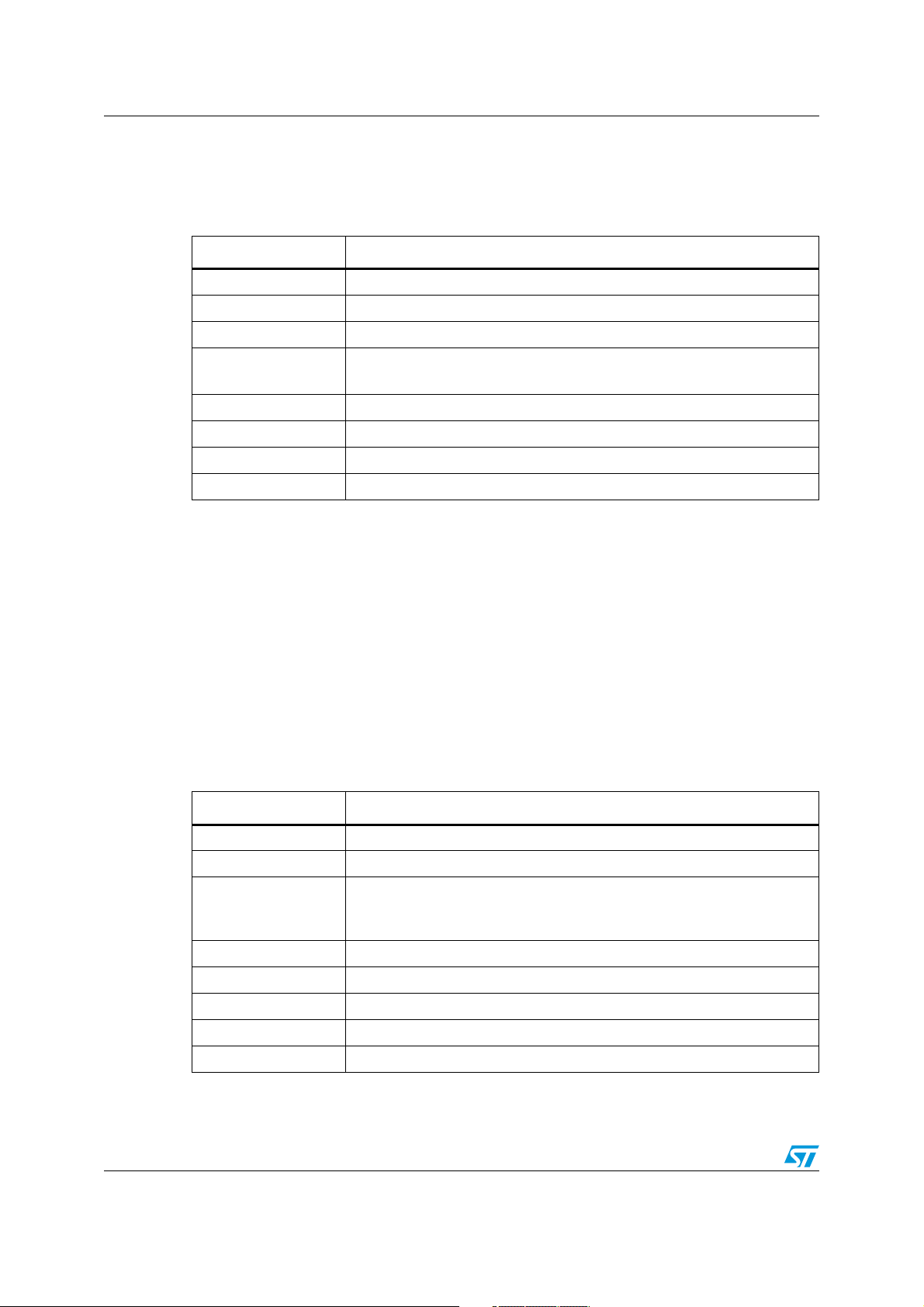
Multi-input embedded GUI library firmware AN3128
4.1.31 Set_LCD_Resolution API global function
Ta bl e 3 6 describes the Set_LCD_Resolution function:
Table 36. Set_LCD_Resolution API global function
Name Description
Function name Set_LCD_Resolution
Function prototype void Set_LCD_Resolution (uint16_t Lcd_Width, uint16_t Lcd_Height)
Behavior description Set LCD panel resolution
Input parameter {x}
Output parameter {x} None
Return value None
Required preconditions None
Called functions No API/HAL layer functions
Example:
int main(void)
{
...
Set_LCD_Resolution( 640, 480 );
GL_LCD_Init();
GL_Clear(White);
...
}
uint16_t Lcd_Width: width of the LCD Panel
uint16_t Lcd_Height: height of the LCD Panel
4.1.32 Set_LastFlashMemoryAddress API global function
Ta bl e 3 7 describes the Set_LastFlashMemoryAddress function:
Table 37. Set_LastFlashMemoryAddress API global function
Name Description
Function name Set_LastFlashMemoryAddress
Function prototype void Set_LastFlashMemoryAddress (uint32_t address)
Set the last Flash memory address.
Behavior description
Input parameter {x} uint32_t address: pointer to the last memory location
Output parameter {x} None
Return value None
Required preconditions None
Called functions No API/HAL layer functions
This address is used to calculate the penultimate Flash memory page,
where the calibration parameters are saved.
52/105 Doc ID 16918 Rev 5
Page 53

AN3128 Multi-input embedded GUI library firmware
Example:
int main(void)
{
...
Set_LastFlashMemoryAddress( 0x08040000 );
...
}
The address of the Flash memory page, where the calibration parameters are saved, is
calculated by subtracting from the last Flash memory address, the size of one memory page
corresponding to “1024” (if a page is “1024 bytes”) and the size in bytes of a memory
pointer, “4” (32-bit), just to align the address to the start of a memory page location.
Therefore, if the Flash memory size is 256 KB and the ROM start address is 0x08000000, it
is necessary to subtract 0x0400+0x0004=0x0404 (1024+4=1028 in decimal) from
0x08040000 that is the last Flash memory address. The result is: 0x0803EFD8.
4.1.33 CursorInit API global function
The cursor is composed of two essential elements. The first is a data structure which
gathers all the necessary variables for regular cursor operations including user-defined
settings, and secondly a graphic appearance displayed on a screen, letting the user know
about its position as a main purpose of it.
In the meantime, the cursor seems to act as a graphic object, but it is different because it is
not involved in the user events management.
Although the actual implementation of the cursor can manage only the input from the
joystick, its structure also supports the input from the mouse connected to a USB port (this
feature is to be available in a future release).
The cursor data structure gathers all variables needed for the regular functioning of service
routines, such as coordinates, press state, pointer to the cursor bitmap mask, and array of
background pixel color. This array, together with a pixels pointer mask serves as storage for
pixels located behind an actual pointer mark. They must be saved before the cursor is
displayed, in order to allow the removal of the cursor when just these stored pixels are
employed to overdraw an old-positioned cursor. Therefore, no information is lost by cursor
drawing (moving).
The CursorInit function initializes a cursor, allocating the memory for the cursor data
structure and afterwards allocating the memory for behind data pixels regarding the number
of pixels listed in the pointer mark header. Ta b le 3 8 describes the CursorInit function:
Table 38. CursorInit API global function
Name Description
Function name CursorInit
Function prototype ErrorStatus CursorInit (GL_uint8_t *PointerMark)
Behavior description
Input parameter {x} *PointerMark: pointer to the cursor mask
Output parameter {x} None
Return value None
Initiate the cursor including allocating memory for structure and behind
array.
Required preconditions None
Called functions No API/HAL layer functions
Doc ID 16918 Rev 5 53/105
Page 54

Multi-input embedded GUI library firmware AN3128
Example:
int main(void)
{
LCD_HW_Parameters_TypeDef* pLcdParam = NewLcdHwParamObj ();
TSC_HW_Parameters_TypeDef* pTscParam = NewTscHwParamObj ();
JOY_HW_Parameters_TypeDef* pJoyParam = NewJoyHwParamObj ();
BTN_HW_Parameters_TypeDef* pBtnParam = NewBtnHwParamObj ();
...
/* Touch Screen Init */
TSC_Init();
/* Joystick Init */
GL_JoyStickConfig_GPIO();
...
CursorInit( GL_NULL );
...
}
4.1.34 CursorShow API global function
The function CursorShow sets an initial value of the Cursor position. Tab le 3 9 describes the
CursorShow function:
Table 39. CursorShow API function
Name Description
Function name CursorShow
Function prototype void CursorShow (GL_uint16_t Xpos, GL_uint16_t Ypos)
Behavior description Show the cursor at the specified position.
Input parameter {x}
Xpos: specifies the X position of cursor
Ypos: specifies the Y position of cursor
Output parameter {x} None
Return value None
Required preconditions None
Called functions No API/HAL layer functions
Example:
int main(void)
{
LCD_HW_Parameters_TypeDef* pLcdParam = NewLcdHwParamObj ();
TSC_HW_Parameters_TypeDef* pTscParam = NewTscHwParamObj ();
JOY_HW_Parameters_TypeDef* pJoyParam = NewJoyHwParamObj ();
BTN_HW_Parameters_TypeDef* pBtnParam = NewBtnHwParamObj ();
...
/* Touch Screen Init */
TSC_Init();
/* Joystick Init */
54/105 Doc ID 16918 Rev 5
Page 55

AN3128 Multi-input embedded GUI library firmware
GL_JoyStickConfig_GPIO();
...
CursorInit( GL_NULL );
CursorShow(195, 60);
...
}
Figure 14. Firmware library API types
Doc ID 16918 Rev 5 55/105
Page 56

Multi-input embedded GUI library firmware AN3128
Figure 15. Firmware library API functions
56/105 Doc ID 16918 Rev 5
Page 57

AN3128 Multi-input embedded GUI library firmware
Figure 16. Firmware library HAL types
4.2 Graphic objects API types
This section describes the graphic object structures, and all their exported API functions and
defined types. See Figure 14, 15, 16.
Here is a description of the defined types used by graphic object source code and a
description of its properties and methods. All API layer types are defined in the file
GraphicObjectTypes.h.
The following structure types can be considered as OOP classes including private/public
properties and public methods. The final graphic objects are instances of these defined
structures.
These structure fields' parameters must not be directly accessed by the final application and
Getxxx/Setxxx methods should be used instead. Obviously the final application could
access these private members, but it should never do so.
The final application must interact with this library using the following public properties and
methods only, as described in the following sections.
Doc ID 16918 Rev 5 57/105
Page 58

Multi-input embedded GUI library firmware AN3128
4.2.1 GL_ErrStatus type
/* Error status types */
typedef enum {
GL_ERROR = 0,
GL_OK = !GL_ERROR
} GL_ErrStatus;
4.2.2 GL_Direction type
/* Direction of LCD orientation */
typedef enum {
GL_HORIZONTAL = 0,
GL_VERTICAL
} GL_Direction;
4.2.3 GL_ButtonStatus type
/* Status value type */
typedef enum {
UNSELECTED = 0,
SELECTED = 1,
NULL = 2
} GL_ButtonStatus;
4.2.4 GL_ObjType type
/* Enumerator for Graphic Object types */
typedef enum{
GL_BUTTON,
GL_RADIO_BUTTON,
GL_CHECKBOX,
GL_LABEL,
GL_SWITCH,
GL_ICON,
GL_COMBOBOX,
GL_SLIDEBAR
}GL_ObjType;
4.2.5 GL_Coordinate_TypeDef type
/* Display Coordinates for the Graphic Object */
typedef struct
{ GL_uint16_t MaxX;
GL_uint16_t MinX;
GL_uint16_t MaxY;
GL_uint16_t MinY;
}GL_Coordinate_TypeDef;
4.2.6 GL_PageControls_TypeDef type
/* Object type */
/* Forward declaration for circular typedefs */
typedef struct GL_PageControlsObj GL_PageControls_TypeDef;
struct GL_PageControlsObj
{
void* objPTR;
GL_Coordinate_TypeDef objCoordinates;
GL_ObjType objType;
};
58/105 Doc ID 16918 Rev 5
Page 59

AN3128 Multi-input embedded GUI library firmware
4.2.7 GL_Label_TypeDef type
/* Object type */
/* Forward declaration for circular typedefs */
typedef struct GL_LabelObj GL_Label_TypeDef;
struct GL_LabelObj
{
const uint8_t
GL_ObjType objType;
const uint8_t label[MAX_LABEL_LENGTH];
__IO uint8_t FontSize;
GL_bool Control_Visible;
GL_ErrStatus (*SetLabelVisible)(GL_Label_TypeDef* pThis, GL_Coordinate_TypeDef
objCoordinates);
};
4.2.8 GL_Button_TypeDef type
/* Object type */
/* Forward declaration for circular typedefs */
typedef struct GL_ButtonObj GL_Button_TypeDef;
struct GL_ButtonObj
{
const uint8_t objName[MAX_NAME_LENGHT];
GL_ObjType objType;
GL_uint8_t* ImageClickedPTR;
GL_uint8_t* ImageUnClickedPTR;
const uint8_t label[MAX_BUTTON_LABEL_LENGTH];
GL_bool isObjectTouched;
GL_bool Control_Visible;
GL_ErrStatus (*SetButtonVisible)(GL_Button_TypeDef* pThis, GL_Coordinate_TypeDef
objCoordinates);
void* (*EventHandler)(void);
};
4.2.9 GL_CheckboxObj_TypeDef type
/* Object type */
/* Forward declaration for circular typedefs */
typedef struct GL_ CheckboxObj GL_CheckboxObj_TypeDef;
struct GL_ButtonObj
{
char objName[MAX_NAME_LENGHT];
GL_ObjType objType;
GL_uint8_t* ImageClickedPTR;
GL_uint8_t* ImageUnClickedPTR;
char label[MAX_CHECKBOX_LABEL_LENGTH];
GL_bool IsChecked;
GL_bool Control_Visible;
GL_ErrStatus (*SetCheckboxVisible)(GL_Checkbox_TypeDef* pThis,
GL_Coordinate_TypeDef objCoordinates);
void* (*EventHandler)(void);
};
Doc ID 16918 Rev 5 59/105
Page 60

Multi-input embedded GUI library firmware AN3128
4.2.10 GL_SwitchObj_TypeDef type
/* Object type */
/* Forward declaration for circular typedefs */
typedef struct GL_SwitchObj GL_Switch_TypeDef;
struct GL_SwitchObj
{
char objName[MAX_NAME_LENGHT];
GL_ObjType objType;
GL_uint8_t* ImageClickedPTR;
GL_uint8_t* ImageUnClickedPTR;
char label_1[MAX_SWITCH_LABEL_LENGTH];
char label_2[MAX_SWITCH_LABEL_LENGTH];
GL_bool isObjectTouched;
GL_bool Control_Visible;
GL_ErrStatus (*SetSwitchVisible)(GL_Switch_TypeDef* pThis, GL_Coordinate_TypeDef
objCoordinates);
void* (*EventHandler)(void);
};
4.2.11 GL_RadioButtonGrp_TypeDef type
/* Object type */
/* Forward declaration for circular typedefs */
typedef struct GL_RadioButtonGrp GL_RadioButtonGrp_TypeDef;
struct GL_RadioButtonGrp
{
const uint8_t objName[MAX_NAME_LENGTH];
GL_uint16_t RadioOptionCount;
GL_PageControls_TypeDef* RadioOptions[MAX_RADIO_OPTIONS];
GL_PageControls_TypeDef* (*AddRadioOption)( GL_RadioButtonGrp_TypeDef* pThis,
const* uint8_t label, void* (*pEventHandler)(void) );
};
4.2.12 GL_RadioButton_TypeDef type
/* Object type */
/* Forward declaration for circular typedefs */
typedef struct GL_RadioButtonOptionObj GL_RadioOption_TypeDef;
struct GL_RadioButtonOptionObj
{
GL_ObjType objType;
GL_RadioButtonGrp_TypeDef* RadioButtonGrp;
GL_uint8_t* ImageCheckedPTR;
GL_uint8_t* ImageUnCheckedPTR;
char label[MAX_RADIO_OPTION_LABEL_LENGTH];
GL_bool IsChecked;
GL_bool Control_Visible;
GL_ErrStatus (*SetRadioButtonVisible)(GL_RadioOption_TypeDef* pThis,
GL_Coordinate_TypeDef objCoordinates);
void* (*EventHandler)(void);
};
60/105 Doc ID 16918 Rev 5
Page 61

AN3128 Multi-input embedded GUI library firmware
4.2.13 GL_ComboBoxGrp_TypeDef type
/* Object type */
/* Forward declaration for circular typedefs */
typedef struct GL_ComboBoxGrp GL_ComboBoxGrp_TypeDef;
struct GL_ComboBoxGrp
{
GL_ObjType objType;
GL_uint8_t* ImageClickedPTR;
GL_uint8_t* ImageUnClickedPTR;
GL_bool Secondary;
GL_PageControls_TypeDef* PrimaryComboOpt;
char objName[MAX_NAME_LENGTH];
GL_bool Control_Visible;
GL_uint16_t ComboOptionCount;
GL_ComboOption_TypeDef* ComboOptions[MAX_COMBO_OPTIONS];
GL_ErrStatus (*AddComboOption)(GL_ComboBoxGrp_TypeDef* pThis, char*
label, void* (*pEventHandler)(void) );
GL_ErrStatus (*SetComboBoxVisible)(GL_ComboBoxGrp_TypeDef* pThis,
GL_Coordinate_TypeDef objCoordinates);
};
4.2.14 GL_ComboOption_TypeDef type
/* Object type */
/* Forward declaration for circular typedefs */
typedef struct GL_ComboOptionObj GL_ComboOption_TypeDef;
struct GL_ComboBoxGrp
{
__IO uint16_t BackColor;
GL_vuint16_t TextColor;
GL_ComboBoxGrp_TypeDef* ComboBoxGrp;
char label[MAX_COMBO_LABEL_LENGTH];
GL_bool IsActive;
void* (*EventHandler)(void);
};
4.2.15 GL_Icon_TypeDef type
/* Object type */
/* Forward declaration for circular typedefs */
typedef struct GL_IconObj GL_Icon_TypeDef;
struct GL_IconObj
{
char objName[MAX_NAME_LENGTH];
GL_ObjType objType;
GL_uint8_t* ImagePTR;
GL_uint16_t ImageWidth;
GL_uint8_t ImageHeight;
GL_bool isObjectTouched;
GL_bool Control_Visible;
GL_ErrStatus (*SetIconVisible)(GL_Icon_TypeDef* pThis, GL_Coordinate_TypeDef
objCoordinates);
void* (*EventHandler)(void);
};
Doc ID 16918 Rev 5 61/105
Page 62

Multi-input embedded GUI library firmware AN3128
4.2.16 GL_Slidebar_TypeDef type
/* Object type */
/* Forward declaration for circular typedefs */
typedef struct GL_SlidebarObj GL_Slidebar_TypeDef;
struct GL_SlidebarObj
{
char objName[MAX_NAME_LENGTH];
GL_ObjType objType;
GL_uint8_t* ImageCursorPTR;
GL_uint8_t* ImageBackgroundPTR;
char label[MAX_SLIDE_LABEL_LENGTH];
GL_Direction Direction;
GL_uint8_t Width;
GL_uint8_t Length;
GL_uint8_t LastValue;
GL_uint8_t PrevValue;
GL_uint8_t MinValue;
GL_uint8_t MaxValue;
GL_uint16_t* BehindCursor;
GL_bool Control_Visible;
GL_ErrStatus (*SetSlidebarVisible)(GL_Slidebar_TypeDef* pThis,
GL_PageControls_TypeDef* pControl);
void* (*EventHandler)(void);
};
4.2.17 GL_Histogram_TypeDef type
/* Object type */
/* Forward declaration for circular typedefs */
typedef struct GL_HistogramObj GL_Histogram_TypeDef;
struct GL_HistogramObj
{
char objName[MAX_NAME_LENGTH];
GL_ObjType objType;
char label_X[MAX_HIST_LABEL_LENGTH];
char label_Y[MAX_HIST_LABEL_LENGTH];
int16_t points[MAX_HIST_POINTS];
GL_uint8_t n_points;
GL_bool Control_Visible;
GL_ErrStatus (*SetHistogramVisible)(GL_Histogram_TypeDef* pThis);
};
4.2.18 GL_GraphChart_TypeDef type
/* Object type */
/* Forward declaration for circular typedefs */
typedef struct GL_GraphChartObj GL_GraphChart_TypeDef;
struct GL_GraphChartObj
{
char objName[MAX_NAME_LENGTH];
GL_ObjType objType;
char label_X[MAX_GRAPH_LABEL_LENGTH];
char label_Y[MAX_GRAPH_LABEL_LENGTH];
int16_t points[MAX_GRAPH_POINTS];
GL_uint8_t n_points;
GL_bool Background;
GL_bool Control_Visible;
GL_ErrStatus (*SetGraphChartVisible)(GL_GraphChart_TypeDef* pThis);
};
62/105 Doc ID 16918 Rev 5
Page 63

AN3128 Multi-input embedded GUI library firmware
4.2.19 GL_ObjDimensions_TypeDef type
/* Object type */
typedef struct
{ GL_uint16_t Height;
GL_uint16_t Length;
}GL_ObjDimensions_TypeDef;
4.2.20 GL_Page_TypeDef type
/* Object type */
/* Forward declaration for circular typedefs */
typedef struct GL_PageObj GL_Page_TypeDef;
struct GL_PageObj
{
char objName[MAX_NAME_LENGTH];
GL_bool Page_Active;
GL_bool Page_Visible;
GL_uint16_t ControlCount;
GL_ErrStatus (*ShowPage)(GL_Page_TypeDef* pThis, GL_bool bVal);
GL_PageControls_TypeDef* PageControls[MAX_CTRL_X_PAGE];
GL_ErrStatus (*SetPage)(GL_Page_TypeDef* pThis, GL_bool bVal);
GL_bool (*GetObjStatus)(GL_Page_TypeDef* pThis, char* objName);
GL_Coordinate_TypeDef (*GetObjCoordinates)(GL_Page_TypeDef* pThis, char*
objName);
};
4.2.21 GL_BusType type
/* Communication Bus Type enumeration */
typedef enum
{
GL_SPI = 0,
GL_FSMC = 1,
GL_OTHER = 2
}GL_BusType;
4.2.22 LCD_HW_Parameters_TypeDef type
/* Object type */
typedef struct /* It contains the Hardware Parameter for the LCD (Bus, Port, Pins)
*/
{
GL_PortType * LCD_Ctrl_Port_NCS;
GL_PortType * LCD_Gpio_Data_Port;
GL_uint16_t LCD_Ctrl_Pin_NCS;
GL_uint16_t LCD_Gpio_Pin_SCK;
GL_uint16_t LCD_Gpio_Pin_MISO;
GL_uint16_t LCD_Gpio_Pin_MOSI;
GL_uint32_t LCD_Rcc_APBPeriph_GPIO;
GL_uint32_t LCD_Rcc_APBPeriph_GPIO_Ncs;
GL_uint32_t LCD_Gpio_RemapPort;
GL_uint32_t LCD_Rcc_Apb_Periph;
GL_uint32_t LCD_Rcc_Ahb_Periph;
GL_SPIType * LCD_Bus_Port;
GL_BusType LCD_Connection_Mode;
}LCD_HW_Parameters_TypeDef;
Doc ID 16918 Rev 5 63/105
Page 64

Multi-input embedded GUI library firmware AN3128
4.2.23 TSC_HW_Parameters_TypeDef type
/* Object type */
typedef struct /* It contains the Hardware Parameter for the Touchscreen Controller
(Bus, Port, Pins) */
{
GL_uint8_t TSC_PortSource;
GL_uint16_t TSC_PinSource;
GL_uint8_t TSC_Exti_IrqChannel;
GL_uint32_t TSC_Exti_Line;
GL_PortType * TSC_Gpio_Port;
GL_uint16_t TSC_Gpio_Pin;
GL_uint16_t TSC_DeviceRegister;
GL_I2CType * TSC_Bus_Port
}TSC_HW_Parameters_TypeDef;
4.2.24 JOY_HW_Parameters_TypeDef type
/* Object type */
typedef struct /* It contains the Hardware Parameter for the Joystick (Bus, Port,
Pins) */
{
GL_uint8_t JOY_PortSource;
GL_uint8_t JOY_PinSource;
GL_PortType * JOY_Select_Port;
GL_PortType * JOY_Right_Port;
GL_PortType * JOY_Left_Port;
GL_PortType * JOY_Up_Port;
GL_PortType * JOY_Down_Port;
GL_uint16_t JOY_Select_Pin;
GL_uint16_t JOY_Right_Pin;
GL_uint16_t JOY_Left_Pin;
GL_uint16_t JOY_Up_Pin;
GL_uint16_t JOY_Down_Pin;
GL_uint32_t JOY_Rcc_APBPeriph_GpioSel;
GL_uint32_t JOY_Rcc_APBPeriph_GpioRight;
GL_uint32_t JOY_Rcc_APBPeriph_GpioLeft;
GL_uint32_t JOY_Rcc_APBPeriph_GpioUp;
GL_uint32_t JOY_Rcc_APBPeriph_GpioDown;
GL_uint8_t JOY_Exti_IrqChannel;
GL_uint32_t JOY_Exti_Line;
GL_uint16_t JOY_DeviceRegister;
}JOY_HW_Parameters_TypeDef;
4.2.25 JOY_ReadMode type
/* Joystick Reading Mode */
typedef enum /* It contains the Reading Mode Parameter for the Joystick (Polling
Mode, IOExpander) */
{
IOEXP_MODE = 0,
POLLING_MODE = 1,
INTERRUPT = 2
}JOY_ReadMode;
64/105 Doc ID 16918 Rev 5
Page 65

AN3128 Multi-input embedded GUI library firmware
4.2.26 BTN_HW_Parameters_TypeDef type
/* Object type */
typedef struct /* It contains the Hardware Parameter for the Push Button (i.e.
Port, Pin) */
{
GL_uint8_t BTN_PortSource;
GL_uint16_t BTN_PinSource;
GL_uint8_t BTN_Exti_IrqChannel;
GL_uint32_t BTN_Exti_Line;
GL_PortType * BTN_Port
GL_uint16_t BTN_Pin
GL_PortType * BUTTON_Port;
GL_uint16_t BUTTON_Pin;
}BTN_HW_Parameters_TypeDef;
4.3 Graphic object API properties
4.3.1 Graphics controls:: properties
Below are some DEFINES that are useful for some of the graphic object parameters.
#define MAX_CTRL_X_PAGE 30 /* Defines the Max number of graphic objects per page */
#define MAX_NAME_LENGTH 22 /* Defines the Max name length for graphic objects */
#define MAX_LABEL_LENGTH 46 /* Defines the Max length for Label (Label objects) */
#define MAX_BUTTON_LABEL_LENGTH 16 /*Defines the Max Label length of Button objects*/
#define MAX_CHECKBOX_LABEL_LENGTH 25 /* Defines the Max Label length for Checkbox */
#define MAX_RADIO_OPTION_LABEL_LENGTH 12 /* Defines the Max Label length of
RadioButton */
#define MAX_RADIO_OPTIONS 3 /* Defines the Max options number of RadioButton group */
#define MAX_COMBO_OPTIONS 10 /* Defines the Max values number of ComboBox objects */
#define MAX_COMBO_LABEL_LENGTH 16 /* Defines the Max Label length for the ComboBox */
#define MAX_SWITCH_LABEL_LENGTH 12 /* Defines the Max Label length for the Switch */
#define MAX_SLIDE_LABEL_LENGTH 16 /* Defines the Max Label length for the Slidebar */
#define MAX_HIST_LABEL_LENGTH 7 /* Defines the Max Label length for the Histogram */
#define MAX_GRAPH_LABEL_LENGTH 7
#define MAX_HIST_POINTS 50 /* Defines the Max number of points for the Histogram */
#define MAX_GRAPH_POINTS 100 /*
/* Defines the Max Label length for the GraphChart */
Defines the Max number of points for the GraphChart */
4.3.2 Graphic Object:: PagesList array
The GraphicObject.h library file exports the following public property:
extern GL_Page_TypeDef* PagesList[];
PagesList contains the array of page pointers created statically by the application. This
object has been left as public for utility means.
4.3.3 LCD:: pLcdParam API properties
LcdHal.c exports the following public structure variable:
LCD_HW_Parameters_TypeDef * pLcdParam; /* LCD Hardware Parameters Structure */
pLcdParam hardware properties allow the final application to set the hardware
communication parameter (Bus GPIO port, GPIO pins).
● LCD_Ctrl_Port_NCS is the GPIO port that contains the GPIO pin which the LCD
control pin is connected to
● LCD_Gpio_Data_Port is the GPIO port dedicated to data transfer
Doc ID 16918 Rev 5 65/105
Page 66

Multi-input embedded GUI library firmware AN3128
● LCD_Ctrl_Pin_NCS is the GPIO pin which the LCD control pin is connected to
● LCD_Gpio_Pin_SCK is the SPI clock pin needed by the SPI interface for the
communication between LCD and micro
● LCD_Gpio_Pin_MISO is the SPI MISO pin needed by the SPI interface for the
communication between LCD and micro
● LCD_Gpio_Pin_MOSI is the SPI MOSI pin needed by the SPI interface for the
communication between LCD and micro
● LCD_Gpio_RemapPort specifies eventually the SPI alternate function mapping
● LCD_Rcc_APBPeriph_GPIO specifies the IO port clock for the LCD data transfer, the
APB peripheral that gates the clock
● LCD_Rcc_APBPeriph_GPIO_Ncs specifies the IO port clock for the NCS control port
of the LCD
● LCD_Rcc_Apb_Periph selects the APB peripheral bus that gates the clock
● LCD_Rcc_Ahb_Periph selects the AHB peripheral bus that gates the clock
● LCD_Bus_Port is the communication interface port used by the LCD (i.e. SPI/I2C)
● LCD_Connection_Mode indicates the way in which the LCD is connected (i.e.
FSMC/SPI/OTHER).
Some examples are listed below:
File: hw_config.h
//LCD Controller DEFINES
#define LCD_CTRL_PORT_NCS GPIOB
#define LCD_GPIO_DATA_PORT GPIOC
#define LCD_CTRL_PIN_NCS GPIO_Pin_2
#define LCD_GPIO_PIN_SCK GPIO_Pin_10
#define LCD_GPIO_PIN_MISO GPIO_Pin_11
#define LCD_GPIO_PIN_MOSI GPIO_Pin_12
#define LCD_GPIO_RCC_APB_PERIPH RCC_APB2Periph_GPIOC
#define LCD_GPIO_RCC_APB_PERIPH_NCS RCC_APB2Periph_GPIOB
#define LCD_GPIO_REMAP_PORT GPIO_Remap_SPI3
#define LCD_RCC_APB_PERIPH RCC_APB1Periph_SPI3
#define LCD_SPI_PORT SPI3
#define LCD_CONNECTION_MODE GL_FSMC
LCD_HW_Parameters_TypeDef* pLcdParam;
File: hw_config.c
void HWConfig_SetHardwareParams(void)
{
...
pLcdParam = NewLcdHwParamObj();
/* Assign the following values for LCD Controller Parameters Structure */
pLcdParam->LCD_Ctrl_Port_NCS = LCD_CTRL_PORT_NCS;
pLcdParam->LCD_Gpio_Data_Port = LCD_GPIO_DATA_PORT;
pLcdParam->LCD_Ctrl_Pin_NCS = LCD_CTRL_PIN_NCS;
pLcdParam->LCD_Ctrl_Pin_NWR = LCD_CTRL_PIN_NWR;
pLcdParam->LCD_Ctrl_Pin_RS = LCD_CTRL_PIN_RS;
pLcdParam->LCD_Gpio_Pin_SCK = LCD_GPIO_PIN_SCK;
pLcdParam->LCD_Gpio_Pin_MISO = LCD_GPIO_PIN_MISO;
pLcdParam->LCD_Gpio_Pin_MOSI = LCD_GPIO_PIN_MOSI;
pLcdParam->LCD_Gpio_RemapPort = LCD_GPIO_REMAP_PORT;
pLcdParam->LCD_Rcc_APBPeriph_GPIO = LCD_GPIO_RCC_APB_PERIPH;
pLcdParam->LCD_Rcc_APBPeriph_GPIO_Ncs = LCD_GPIO_RCC_APB_PERIPH_NCS;
66/105 Doc ID 16918 Rev 5
Page 67

AN3128 Multi-input embedded GUI library firmware
pLcdParam->LCD_Rcc_Apb_Periph = LCD_RCC_APB_PERIPH;
pLcdParam->LCD_Rcc_Ahb_Periph = LCD_RCC_AHB_PERIPH;
pLcdParam->LCD_Bus_Port = LCD_SPI_PORT;
pLcdParam->LCD_Connection_Mode = LCD_CONNECTION_MODE;
...
}
4.3.4 Touchscreen:: pTscParam API properties
TscHal.c exports the following public structure variable:
TSC_HW_Parameters_TypeDef * pTscHwParam; /* Touchscreen Hardware Parameters
Structure */
pTscParam properties allow setting the hardware communication parameters (Bus GPIO
port, GPIO pins).
● TSC_PortSource selects the GPIO port to be used as source for event output for the
touchscreen controller
● TSC_PinSource is the GPIO pin for the event output
● TSC_Exti_IrqChannel selects the external line interrupts
● TSC_Exti_Line selects the external interrupt line which the touchscreen controller is
connected to
● TSC_Gpio_Port is the GPIO port needed for the communication between the
touchscreen controller and micro
● TSC_Gpio_Pin is the GPIO pin needed for the communication between the
touchscreen controller and micro
● TSC_DeviceRegister selects the touchscreen controller if two STMPE811s are
connected to be used as the IO expander
● TSC_Bus_Port is the communication interface channel for the communication between
the touchscreen controller and the microcontroller.
Some examples are listed below:
File: hw_config.h
// Touchscreen Controller DEFINES
#define TSC_GPIO_PORT_SOURCE GPIO_PortSourceGPIOB
#define TSC_GPIO_PIN_SOURCE GPIO_PinSource14
#define TSC_EXTI_IRQ_CHANNEL EXTI15_10_IRQn
#define TSC_EXTI_LINE EXTI_Line14
#define TSC_GPIO_PORT GPIOA
#define TSC_GPIO_PIN GPIO_Pin_14
#define TSC_I2C_DEVICE_REGISTER 0x82
#define TSC_I2C_PORT I2C1
TSC_HW_Parameters_TypeDef* pTscParam;
File: hw_config.c
void HWConfig_SetHardwareParams(void)
{
...
pTscParam = NewTscHwParamObj();
/* Assign the following value for Touchscreen Controller
Parameters Structure */
pTscParam->TSC_PortSource = GL_GPIO_TSC_PORT_SOURCE;
pTscParam->TSC_PinSource = GL_GPIO_TSC_PIN_SOURCE;
pTscParam->TSC_Exti_IrqChannel = TSC_EXTI_IRQ_CHANNEL;
pTscParam->TSC_Exti_Line = TSC_EXTI_LINE;
Doc ID 16918 Rev 5 67/105
Page 68

Multi-input embedded GUI library firmware AN3128
pTscParam->TSC_Gpio_Port = TSC_GPIO_PORT;
pTscParam->TSC_Gpio_Pin = TSC_GPIO_PIN;
pTscParam->TSC_DeviceRegister = TSC_I2C_DEVICE_REGISTER;
pTscParam->TSC_Bus_Port = TSC_I2C_PORT;
}
4.3.5 Joystick:: pJoyParam API properties
JoyHal.c exports the following public structure variable:
JOY_HW_Parameters_TypeDef* pJoyParam; /*Joystick Hardware Parameters Structure */
pJoyHwParam properties allow setting the hardware communication parameters (Bus GPIO
port, GPIO pins).
● JOY_PortSource selects the GPIO port to be used as source for event output for the
joystick
● JOY_PinSource is the GPIO pin for the event output
● JOY_Select_Port selects the GPIO port to be used for the select command on the
joystick
● JOY_Select_Pin selects the GPIO pin to be used for the select command on the
joystick
● JOY_Right_Port selects the GPIO port to be used for the right command on the joystick
● JOY_Right_Pin selects the GPIO pin to be used for the right command on the joystick
● JOY_Left_Port selects the GPIO port to be used for the left command on the joystick
● JOY_Left_Pin selects the GPIO pin to be used for the left command on the joystick
● JOY_Up_Port selects the GPIO port to be used for the up command on the joystick
● JOY_Up_Pin selects the GPIO pin to be used for the up command on the joystick
● JOY_Down_Port selects the GPIO port to be used for the down command on the
joystick
● JOY_Down_Pin selects the GPIO pin to be used for the down command on the joystick
● JOY_Rcc_APBPeriph_GpioSel selects the APB peripheral bus that gates the select
port of the joystick
● JOY_Rcc_APBPeriph_GpioRight selects the APB peripheral bus that gates the right
port of the joystick
● JOY_Rcc_APBPeriph_GpioLeft selects the APB peripheral bus that gates the left port
of the joystick
● JOY_Rcc_APBPeriph_GpioUp selects the APB peripheral bus that gates the up port of
the joystick
● JOY_Rcc_APBPeriph_GpioDown selects the APB peripheral bus that gates the down
port of the joystick
● JOY_Exti_IrqChannel selects the external line interrupts
● JOY_Exti_Line selects the external interrupt line which the joystick is connected to
● JOY_DeviceRegister if the joystick is connected to an IO expander (i.e. STMPE811) it
selects the STMPE811 device if, for example, two STMPE811s are connected to be
used as the IO expander.
68/105 Doc ID 16918 Rev 5
Page 69

AN3128 Multi-input embedded GUI library firmware
Some examples are listed below:
File: hw_config.h
/* Joystick DEFINES */
#define GL_GPIO_JOY_PORT_SOURCE GPIO_PortSourceGPIOB
#define GL_GPIO_JOY_PIN_SOURCE GPIO_PinSource14
#define JOY_GPIO_SELECT_PORT GPIOG
#define JOY_GPIO_SELECT_PIN GPIO_Pin_7
#define JOY_GPIO_RIGHT_PORT GPIOG
#define JOY_GPIO_RIGHT_PIN GPIO_Pin_13
#define JOY_GPIO_LEFT_PORT GPIOG
#define JOY_GPIO_LEFT_PIN GPIO_Pin_14
#define JOY_GPIO_UP_PORT GPIOG
#define JOY_GPIO_UP_PIN GPIO_Pin_15
#define JOY_GPIO_DOWN_PORT GPIOD
#define JOY_GPIO_DOWN_PIN GPIO_Pin_3
#define JOY_GPIO_RCC_APB_PERIPH1 RCC_APB2Periph_GPIOG
#define JOY_GPIO_RCC_APB_PERIPH2 RCC_APB2Periph_GPIOG
#define JOY_GPIO_RCC_APB_PERIPH3 RCC_APB2Periph_GPIOG
#define JOY_GPIO_RCC_APB_PERIPH4 RCC_APB2Periph_GPIOG
#define JOY_GPIO_RCC_APB_PERIPH5 RCC_APB2Periph_GPIOD
#define JOY_EXTI_IRQ_CHANNEL EXTI15_10_IRQn
#define JOY_EXTI_LINE EXTI_Line14
#define JOY_I2C_DEVICE_REGISTER 0x88
JOY_HW_Parameters_TypeDef * pJoyParam;
File: hw_config.c
void HWConfig_SetHardwareParams(void)
{
...
/* Assign the following value for Joystick Parameters Structure */
pJoyParam->JOY_PortSource = GL_GPIO_JOY_PORT_SOURCE;
pJoyParam->JOY_PinSource = GL_GPIO_JOY_PIN_SOURCE;
pJoyParam->JOY_Select_Port = JOY_GPIO_SELECT_PORT;
pJoyParam->JOY_Select_Pin = JOY_GPIO_SELECT_PIN;
pJoyParam->JOY_Right_Port = JOY_GPIO_RIGHT_PORT;
pJoyParam->JOY_Right_Pin = JOY_GPIO_RIGHT_PIN;
pJoyParam->JOY_Left_Port = JOY_GPIO_LEFT_PORT;
pJoyParam->JOY_Left_Pin = JOY_GPIO_LEFT_PIN;
pJoyParam->JOY_Up_Port = JOY_GPIO_UP_PORT;
pJoyParam->JOY_Up_Pin = JOY_GPIO_UP_PIN;
pJoyParam->JOY_Down_Port = JOY_GPIO_DOWN_PORT;
pJoyParam->JOY_Down_Pin = JOY_GPIO_DOWN_PIN;
pJoyParam->JOY_Rcc_APBPeriph_GpioSel = JOY_GPIO_RCC_APB_PERIPH1;
pJoyParam->JOY_Rcc_APBPeriph_GpioRight = JOY_GPIO_RCC_APB_PERIPH2;
pJoyParam->JOY_Rcc_APBPeriph_GpioLeft = JOY_GPIO_RCC_APB_PERIPH3;
pJoyParam->JOY_Rcc_APBPeriph_GpioUp = JOY_GPIO_RCC_APB_PERIPH4;
pJoyParam->JOY_Rcc_APBPeriph_GpioDown = JOY_GPIO_RCC_APB_PERIPH5;
pJoyParam->JOY_Exti_IrqChannel = JOY_EXTI_IRQ_CHANNEL;
pJoyParam->JOY_Exti_Line = JOY_EXTI_LINE;
pJoyParam->JOY_DeviceRegister = JOY_I2C_DEVICE_REGISTER;
...
}
Doc ID 16918 Rev 5 69/105
Page 70

Multi-input embedded GUI library firmware AN3128
4.3.6 Push user button:: pBtnParam API properties
JoyHal.c exports the following public structure variable:
BTN_HW_Parameters_TypeDef* pBtnParam; /*Push Button Hardware Parameters Structure */
pBtnParam properties allow setting the hardware communication parameters (GPIO port,
GPIO pins).
● BTN_PortSource selects the GPIO port to be used as source for event output for the
push button
● BTN_PinSource is the GPIO pin for the event output
● BTN_Exti_IrqChannel selects the external line interrupts
● BTN_Exti_Line selects the external interrupt line which the push button is connected to
● BTN_Port is the GPIO port needed for the communication between push button and
micro
● BTN_Pin is the GPIO pin needed for the communication between push button and
micro
Some examples are listed below:
File: hw_config.h
// Push Button DEFINES
#define BUTTON_GPIO_PORT GPIOG
#define BUTTON_GPIO_PIN GPIO_Pin_8
BTN_HW_Parameters_TypeDef * pBtnParam;
File: hw_config.c
void HWConfig_SetHardwareParams(void)
{
...
pBtnParam = NewBtnHwParamObj ();
/* Assign the following values for Button Parameters structure*/
pBtnParam->BTN_Port = USER_BUTTON_PORT;
pBtnParam->BTN_Pin = USER_BUTTON_PIN;
...
}
70/105 Doc ID 16918 Rev 5
Page 71

AN3128 Multi-input embedded GUI library firmware
4.4 HAL layer firmware overview
The following section describes the hardware abstraction layer function used by the upper
API layer described in the previous section. All the library microcontroller hardware
dependent functions and related defined types are described in this section. See Figure 14,
15, 16.
The final application should never directly use these HAL functions, and it should only
manage LCD, touchscreen, and joystick through API layer functions as described above.
4.5 HAL types
4.5.1 GL_bool type
/* Boolean Definition Type */
typedef enum
{
GL_FALSE = 0,
GL_TRUE = !GL_FALSE,
}GL_bool;
4.5.2 GL_FlagStatus/GL_ITStatus type
/* Flag/IT Status Type */
typedef enum /* It contains the status parameter of LCD Flags/Interrupts
(GL_RESET, GL_SET) */
{
GL_RESET = 0,
GL_SET = !GL_RESET,
}GL_FlagStatus, GL_ITStatus;
4.5.3 GL_SignalActionType type
/* Signal state enumeration */
typedef enum
{
GL_LOW = Bit_RESET,
GL_HIGH = Bit_SET
}GL_SignalActionType;
4.5.4 GL_FunctionalState type
/* Error status types */
typedef enum {
GL_DISABLE = 0,
GL_ENABLE = GL_DISABLE
} GL_FunctionalState;
4.5.5 TSC_I2C_SettingsType type
/* The TouchScreen I2C Peripheral settings */
typedef struct
{
GL_I2CType * TSC_I2C_Ptr;
GL_uint32_t TSC_I2C_Clock;
GL_uint16_t TSC_I2C_Address;
}TSC_I2C_SettingsType;
Doc ID 16918 Rev 5 71/105
Page 72
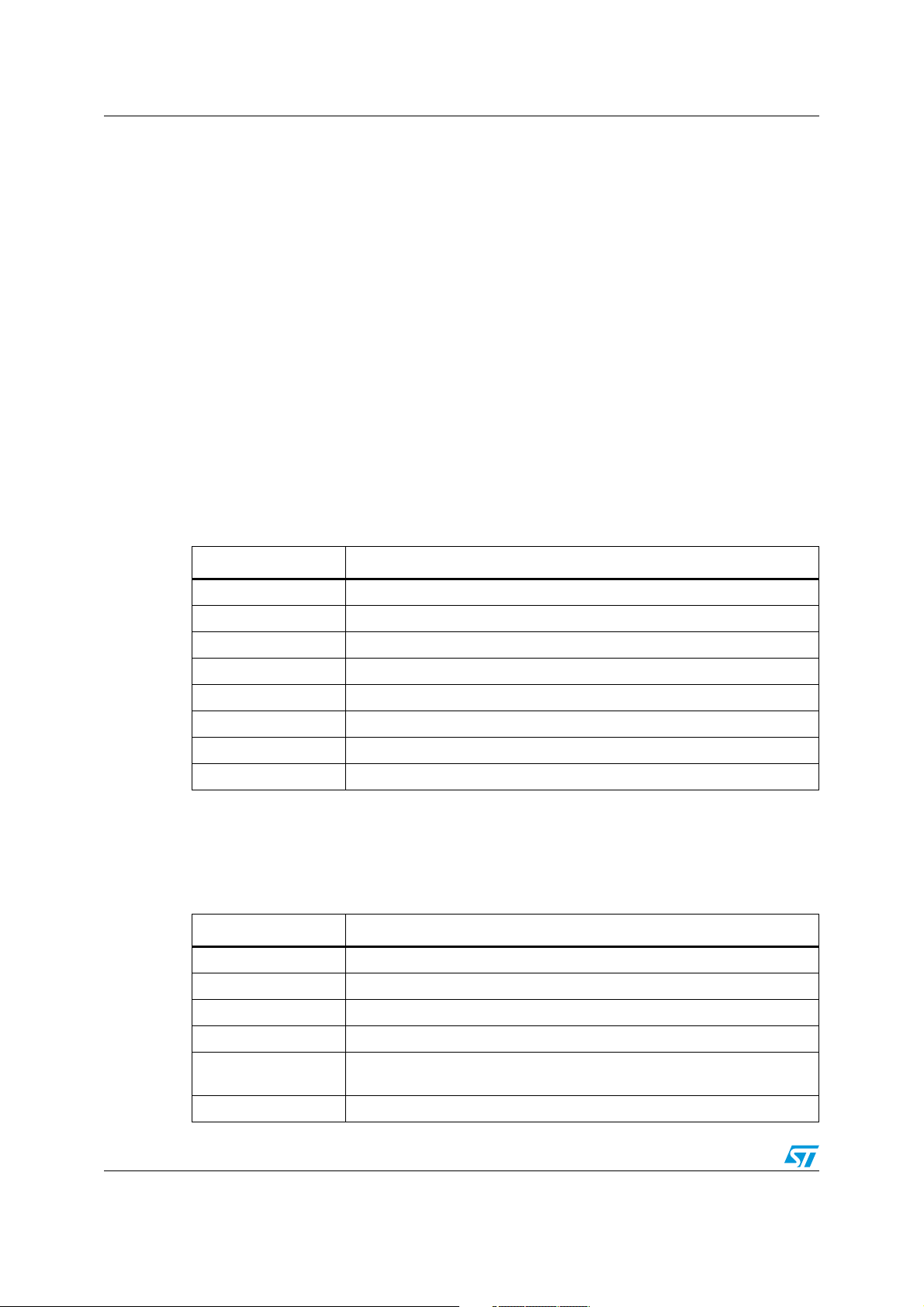
Multi-input embedded GUI library firmware AN3128
4.5.6 TSC_Flash_TestStatus type
/* For Flash Programming */
typedef enum {FAILED = 0, PASSED = !FAILED} TSC_Flash_TestStatus;
4.5.7 GL_LCD_TypeDef type
/* LCD Structure definition */
typedef enum
{
__IO uint16_t LCD_REG;
__IO uint16_t LCD_RAM;
} GL_LCD_TypeDef;
4.6 HAL functions
4.6.1 NewLcdHwParamObj HAL function
Ta bl e 4 0 describes the NewLcdHwParamObj function of the hardware abstraction layer.
Table 40. NewLcdHwParamObj
Name Description
Function name NewLcdHwParamObj
Function prototype LCD_HW_Parameters_TypeDef* NewLcdHwParamObj (void)
Behavior description Create and initialize a new LCD Hw parameter structure object
Input parameter {x} None
Output parameter {x} None
Return value The created object pointer
Required preconditions None
Called functions None
4.6.2 GL_SetTextColor HAL function
Ta bl e 4 1 describes the GL_SetTextColor function of the hardware abstraction layer.
Table 41. GL_SetTextColor
Name Description
Function name GL_SetTextColor
Function prototype void GL_SetTextColor (__IO uint16_t TextColor)
Behavior description Sets the text color
Input parameter {x} Color: specifies the text color code RGB (5-6-5)
Output parameter {x}
Return value None
72/105 Doc ID 16918 Rev 5
TextColor: text color global variable used by GL_DrawChar and
GL_DrawPicture functions
Page 73

AN3128 Multi-input embedded GUI library firmware
Table 41. GL_SetTextColor (continued)
Name Description
Required preconditions None
Called functions LCD_SetTextColor (TextColor)
4.6.3 GL_SetBackColor HAL function
Ta bl e 4 2 describes the GL_SetBackColor function of the hardware abstraction layer.
Table 42. GL_SetBackColor
Name Description
Function name GL_SetBackColor
Function prototype void GL_SetBackColor (__IO uint16_t BackColor)
Behavior description Sets the background color
Input parameter {x} Color: specifies the background color code RGB(5-6-5)
Output parameter {x}
BackColor: background color global variable used by GL_DrawChar and
GL_DrawPicture functions
Return value None
Required preconditions None
Called functions LCD_SetBackColor (BackColor)
4.6.4 GL_Clear HAL function
Ta bl e 4 3 describes the GL_Clear function of the hardware abstraction layer.
Table 43. GL_Clear
Name Description
Function name GL_Clear
Function prototype void GL_Clear (GL_uint16_t color)
Behavior description Clears the whole LCD
Input parameter {x} Color: the color of the background
Output parameter {x} None
Return value None
Required preconditions None
Called functions LCD_Clear (Color)
Doc ID 16918 Rev 5 73/105
Page 74

Multi-input embedded GUI library firmware AN3128
4.6.5 GL_LCD_DrawCharTransparent HAL function
Ta bl e 4 4 describes the GL_LCD_DrawCharTransparent function of the hardware abstraction
layer.
Table 44. GL_LCD_DrawCharTransparent HAL function
Name Description
Function name GL_LCD_DrawCharTransparent
Function prototype
Behavior description Draws a character on the LCD without background
Input parameter {x}
Output parameter {x} None
Return value None
Required preconditions None
void GL_LCD_DrawCharTransparent (uint8_t Xpos, uint16_t Ypos, uc8 *c)
//8bit char
Xpos: the line where the character shape is displayed. This parameter can
be one of the following values: - Linex: where x is 0..9
Ypos: start column address.
c: pointer to the character data
Called functions None
4.6.6 GL_LCD_DrawChar HAL function
Ta bl e 4 5 describes the GL_LCD_DrawChar function of the hardware abstraction layer.
Table 45. GL_LCD_DrawChar HAL function
Name Description
Function name GL_LCD_DrawChar
Function prototype void GL_LCD_DrawChar (uint8_t Xpos, uint16_t Ypos, uc8 *c) //8bit char
Behavior description Draws a character on the LCD with background color
Xpos: the line where the character shape is displayed. This parameter can
Input parameter {x}
Output parameter {x} None
Return value None
Required preconditions None
Called functions None
be one of the following values: Linex: where x is 0..9
Ypos: start column address.
c: pointer to the character data
74/105 Doc ID 16918 Rev 5
Page 75

AN3128 Multi-input embedded GUI library firmware
4.6.7 GL_DisplayAdjStringLine HAL function
Ta bl e 4 6 describes the GL_DisplayAdjStringLine function of the hardware abstraction layer.
Table 46. GL_DisplayAdjStringLine
Name Description
Function name GL_DisplayAdjStringLine
Function prototype
Behavior description Displays a maximum of 20 char on the LCD
Input parameter {x}
Output parameter {x} None
Return value None
Required preconditions None
Called functions None
void GL_DisplayAdjStringLine (GL_uint8_t Line, GL_uint16_t Column,
GL_uint8_t *ptr, GL_bool Transparent_Flag)
Line: the line where the character shape is displayed
*ptr: pointer to the string to display on LCD
4.6.8 GL_LCD_DisplayChar HAL function
Ta bl e 4 7 describes the GL_LCD_DisplayChar function of the hardware abstraction layer.
Table 47. GL_LCD_DisplayChar
Name Description
Function name GL_LCD_DisplayChar
Function prototype
Behavior description Displays one character (16 dots width, 24 dots height)
Input parameter {x}
Output parameter {x} None
Return value None
Required preconditions None
Called functions GL_LCD_DrawCharTransparent or GL_LCD_DrawChar
void GL_LCD_DisplayChar (uint8_t Line, uint16_t Column, uint8_t Ascii,
GL_bool Transparent_Flag)
Line: the line where the character shape is displayed. This parameter can
be one of the following values: Linex: where x can be 0..9
Column: start column address
Ascii: character ascii code, must be between 0x20 and 0x7E
GL_bool Trasparent_Flag, if TRUE it does not print a BackColor
Doc ID 16918 Rev 5 75/105
Page 76

Multi-input embedded GUI library firmware AN3128
4.6.9 GL_SetDisplayWindow HAL function
Ta bl e 4 8 describes the GL_SetDisplayWindow function of the hardware abstraction layer.
Table 48. GL_SetDisplayWindow
Name Description
Function name GL_SetDisplayWindow
Function prototype
Behavior description Sets a display window
Input parameter {x}
Output parameter {x} None
Return value None
Required preconditions None
Called functions LCD_SetDisplayWindow(Xpos, Ypos, Height, Width)
void GL_SetDisplayWindow (GL_uint8_t Xpos, GL_uint16_t Ypos,
GL_uint8_t Height, GL_uint16_t Width)
Xpos: specifies the X bottom left position
Ypos: specifies the Y bottom left position
Height: display window height.
Width: display window width.
4.6.10 GL_DrawLine HAL function
Ta bl e 4 9 describes the GL_DrawLine function of the hardware abstraction layer.
Table 49. GL_DrawLine
Name Description
Function name GL_DrawLine
Function prototype
Behavior description Displays a line
Input parameter {x}
Output parameter {x} None
Return value None
Required preconditions None
Called functions LCD_DrawLine (Xpos, Ypos, Length, Direction)
void GL_DrawLine (GL_uint8_t Xpos, GL_uint16_t Ypos, GL_uint16_t
Length, GL_uint8_t Direction)
Xpos: specifies the X position.
Ypos: specifies the Y position.
Length: line length.
Direction: line direction. This parameter can be one of the following values:
Vertical or Horizontal.
76/105 Doc ID 16918 Rev 5
Page 77

AN3128 Multi-input embedded GUI library firmware
4.6.11 GL_DrawBMP HAL function
Ta bl e 5 0 describes the GL_DrawBMP function of the hardware abstraction layer.
Table 50. GL_DrawBMP
Name Description
Function name GL_DrawBMP
Function prototype void GL_DrawBMP (GL_uint8_t* ptrBitmap)
Behavior description Displays a bitmap picture
Input parameter {x} BmpAddress: Bmp picture address
Output parameter {x} None
Return value None
Required preconditions None
Called functions None
4.6.12 GL_SetFont HAL function
Ta bl e 5 1 describes the GL_SetFont function of the hardware abstraction layer.
Table 51. GL_SetFont
Name Description
Function name GL_SetFont
Function prototype void GL_SetFont (GL_uint8_t uFont)
Behavior description Sets the font (big or small)
Input parameter {x} uFont: specifies the font (GL_FONT_BIG or GL_FONT_SMALL)
Output parameter {x} None
Return value None
Required preconditions None
Called functions None
4.6.13 GL_BackLightSwitch HAL function
Ta bl e 5 2 describes the GL_BackLightSwitch function of the hardware abstraction layer.
Table 52. GL_BackLightSwitch
Name Description
Function name GL_BackLightSwitch
Function prototype void GL_BackLightSwitch (GL_uint8_t uint8_t_State)
Behavior description Switches the backlight either ON or OFF
Input parameter {x} State: ON or OFF
Doc ID 16918 Rev 5 77/105
Page 78

Multi-input embedded GUI library firmware AN3128
Table 52. GL_BackLightSwitch (continued)
Name Description
Output parameter {x} None
Return value None
Required preconditions None
Called functions None
4.6.14 GL_BUSConfig HAL function
Ta bl e 5 3 describes the GL_BUSConfig function of the hardware abstraction layer.
Table 53. GL_BUSConfig
Name Description
Function name GL_BUSConfig
Function prototype void GL_BUSConfig (GL_BusType busType)
Behavior description Configures the BUS communication interface
Input parameter {x} Bus type: GL_SPI or GL_FSMC
Output parameter {x} None
Return value None
Required preconditions None
Called functions None
4.6.15 GL_LCD_Init HAL function
Ta bl e 5 4 describes the GL_LCD_Init function of the hardware abstraction layer.
Table 54. GL_LCD_Init
Name Description
Function name GL_LCD_Init
Function prototype void GL_LCD_Init (void)
Behavior description Initializes the LCD
Input parameter {x} None
Output parameter {x} None
Return value None
Required preconditions None
Called functions LCD_Setup()
78/105 Doc ID 16918 Rev 5
Page 79

AN3128 Multi-input embedded GUI library firmware
4.6.16 NewTscHwParamObj HAL function
Ta bl e 5 5 describes the NewTscHwParamObj function of the hardware abstraction layer.
Table 55. NewTscHwParamObj
Name Description
Function name NewTscHwParamObj
Function prototype TSC_HW_Parameters_TypeDef* NewTscHwParamObj (void)
Behavior description
Input parameter {x} None
Output parameter {x} None
Return value The created object pointer
Required preconditions None
Called functions None
Create and initialize a new touchscreen Hw parameter structure object used
by the micro in order to manage the touchscreen controller device
4.6.17 NewJoyHwParamObj HAL function
Ta bl e 5 6 describes the NewJoyHwParamObj function of the hardware abstraction layer.
Table 56. NewJoyHwParamObj
Name Description
Function name NewJoyHwParamObj
Function prototype JOY_HW_Parameters_TypeDef* NewJoyHwParamObj (void)
Behavior description
Input parameter {x} None
Output parameter {x} None
Create and initialize a new joystick Hw parameter structure object used by
the micro in order to manage the joystick device
Return value The created object pointer
Required preconditions None
Called functions None
4.6.18 NewBtnHwParamObj HAL function
Ta bl e 5 7 describes the NewBtnHwParamObj function of the hardware abstraction layer.
Table 57. NewBtnHwParamObj HAL
Name Description
Function name NewBtnHwParamObj
Function prototype BTN_HW_Parameters_TypeDef* NewBtnHwParamObj (void)
Doc ID 16918 Rev 5 79/105
Page 80

Multi-input embedded GUI library firmware AN3128
Table 57. NewBtnHwParamObj HAL (continued)
Name Description
Behavior description
Input parameter {x} None
Output parameter {x} None
Return value The created object pointer
Required preconditions None
Called functions None
Create and initialize a new button Hw parameter structure object used by
the micro in order to manage the push button device
4.6.19 GL_GPIO_Init HAL function
Ta bl e 5 8 describes the GL_GPIO_Init function of the hardware abstraction layer.
Table 58. GL_GPIO_Init
Name Description
Function name GL_GPIO_Init
Function prototype
Behavior description
Input parameter {x}
Output parameter {x} None
void GL_GPIO_Init (GPIO_TypeDef* GPIOx, GL_GPIO_InitTypeDef*
GPIO_InitStruct)
Initializes the GPIOx peripheral according to the specified parameters in the
GPIO_InitStruct
GPIOx: where x can be 1, 2, 3, … to select the GPIO port.
GPIO_InitStruct: pointer to GPIO_InitTypeDef structure that contains the
configuration information for the specified GPIO peripheral
Return value None
Required preconditions None
Called functions GPIO_Init (GPIOx, GPIO_InitStruct)
4.6.20 GL_SPI_Init HAL function
Ta bl e 5 9 describes the GL_SPI_Init function of the hardware abstraction layer.
Table 59. GL_SPI_Init
Name Description
Function name GL_SPI_Init
Function prototype
Behavior description
80/105 Doc ID 16918 Rev 5
void GL_SPI_Init (SPI_TypeDef* SPIx, GL_SPI_InitTypeDef*
SPI_InitStruct)
Initializes the SPIx peripheral according to the specified parameters in the
SPI_InitStruct.
Page 81

AN3128 Multi-input embedded GUI library firmware
Table 59. GL_SPI_Init (continued)
Name Description
SPIx: where x can be 1, 2 or 3 to select the SPI peripheral.
Input parameter {x}
Output parameter {x} None
Return value None
Required preconditions None
Called functions SPI_Init (SPIx, &tmp)
SPI_InitStruct: pointer to a SPI_InitTypeDef structure that contains the
configuration information for the specified SPI peripheral.
4.6.21 GL_NVIC_SetVectorTable HAL function
Ta bl e 6 0 describes the GL_NVIC_SetVectorTable function of the hardware abstraction layer.
Table 60. GL_NVIC_SetVectorTable
Name Description
Function name GL_NVIC_SetVectorTable
Function prototype
void GL_NVIC_SetVectorTable (GL_uint32_t NVIC_VectTab, GL_uint32_t
Offset)
Behavior description Sets the vector table location and offset
NVIC_VectTab: specifies if the vector table is in RAM or Flash memory. This
parameter can be one of the following values:
Input parameter {x}
Output parameter {x} None
Return value None
Required preconditions None
Called functions NVIC_SetVectorTable (NVIC_VectTab, Offset)
– NVIC_VectTab_RAM
– NVIC_VectTab_FLASH
Offset: vector table base offset field. This value must be a multiple of 0x100.
4.6.22 GL_NVIC_Init HAL function
Ta bl e 6 1 describes the GL_NVIC_Init function of the hardware abstraction layer.
Table 61. GL_NVIC_Init
Name Description
Function name GL_NVIC_Init
Function prototype void GL_NVIC_Init (GL_NVIC_InitTypeDef* NVIC_InitStruct)
Behavior description
Initializes the NVIC peripheral according to the specified parameters in the
NVIC_InitStruct
Input parameter {x}
NVIC_InitStruct: pointer to a NVIC_InitTypeDef structure that contains the
configuration information for the specified NVIC peripheral.
Doc ID 16918 Rev 5 81/105
Page 82

Multi-input embedded GUI library firmware AN3128
Table 61. GL_NVIC_Init (continued)
Name Description
Output parameter {x} None
Return value None
Required preconditions None
Called functions NVIC_Init (NVIC_InitStruct);
4.6.23 GL_NVIC_PriorityGroupConfig HAL function
Ta bl e 6 2 describes the GL_NVIC_PriorityGroupConfig function of the hardware abstraction
layer.
Table 62. GL_NVIC_PriorityGroupConfig
Name Description
Function name GL_NVIC_PriorityGroupConfig
Function prototype void GL_NVIC_PriorityGroupConfig (GL_uint32_t NVIC_PriorityGroup)
Behavior description Configures the priority grouping: pre-emption priority and subpriority
NVIC_PriorityGroup: specifies the priority grouping bits length. This
parameter can be one of the following values:
– NVIC_PriorityGroup_0: 0 bits for pre-emption priority, 4 bits for subpriority
Input parameter {x}
Output parameter {x} None
– NVIC_PriorityGroup_1: 1 bits for pre-emption priority, 3 bits for subpriority
– NVIC_PriorityGroup_2: 2 bits for pre-emption priority, 2 bits for subpriority
– NVIC_PriorityGroup_3: 3 bits for pre-emption priority, 1 bits for subpriority
– NVIC_PriorityGroup_4: 4 bits for pre-emption priority, 0 bits for subpriority
Return value None
Required preconditions None
Called functions NVIC_PriorityGroupConfig (NVIC_PriorityGroup)
4.6.24 GL_EXTI_DeInit HAL function
Ta bl e 6 3 describes the GL_EXTI_DeInit function of the hardware abstraction layer.
Table 63. GL_EXTI_DeInit
Name Description
Function name GL_EXTI_DeInit
Function prototype void GL_EXTI_DeInit (void)
Behavior description Deinitializes the EXTI peripheral registers to their default reset values
Input parameter {x} None
Output parameter {x} None
Return value None
82/105 Doc ID 16918 Rev 5
Page 83
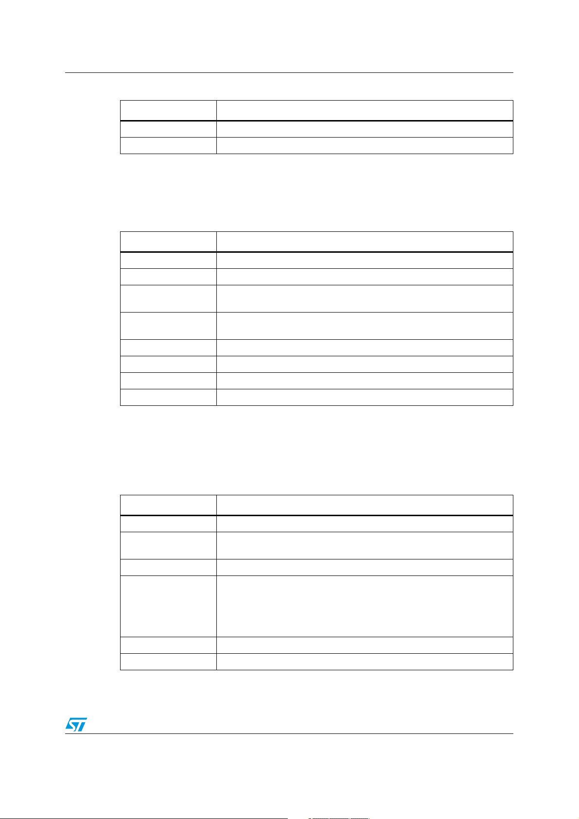
AN3128 Multi-input embedded GUI library firmware
Table 63. GL_EXTI_DeInit (continued)
Name Description
Required preconditions None
Called functions EXTI_DeInit()
4.6.25 GL_EXTI_Init HAL function
Ta bl e 6 4 describes the GL_EXTI_Init function of the hardware abstraction layer.
Table 64. GL_EXTI_Init
Name Description
Function name GL_EXTI_Init
Function prototype void GL_EXTI_Init (GL_EXTI_InitTypeDef* EXTI_InitStruct)
Behavior description
Input parameter {x}
Initializes the EXTI peripheral according to the specified parameters in the
EXTI_InitStruct.
EXTI_InitStruct: pointer to an EXTI_InitTypeDef structure that contains the
configuration information for the EXTI peripheral
Output parameter {x} None
Return value None
Required preconditions None
Called functions EXTI_Init (EXTI_InitStruct)
4.6.26 GL_GPIO_EXTILineConfig HAL function
Ta bl e 6 5 describes the GL_GPIO_EXTILineConfig function of the hardware abstraction
layer.
Table 65. GL_GPIO_EXTILineConfig
Name Description
Function name GL_GPIO_EXTILineConfig
Function prototype
Behavior description Selects the GPIO pin used as the EXTI Line
Input parameter {x}
void GL_GPIO_EXTILineConfig (GL_uint8_t GPIO_PortSource, GL_uint8_t
GPIO_PinSource)
GPIO_PortSource: selects the GPIO port to be used as source for EXTI
lines. This parameter can be GPIO_PortSourceGPIOx where x can be
(A..G).
GPIO_PinSource: specifies the EXTI line to be configured. This parameter
can be GPIO_PinSourcex where x can be (0..15).
Output parameter {x} None
Return value None
Doc ID 16918 Rev 5 83/105
Page 84

Multi-input embedded GUI library firmware AN3128
Table 65. GL_GPIO_EXTILineConfig (continued)
Name Description
Required preconditions None
Called functions GPIO_EXTILineConfig (GPIO_PortSource, GPIO_PinSource)
4.6.27 GL_EXTI_TSC_IRQHandler HAL function
Ta bl e 6 6 describes the GL_EXTI_TSC_IRQHandler function of the hardware abstraction
layer.
Table 66. GL_EXTI_TSC_IRQHandler
Name Description
Function name GL_EXTI_TSC_IRQHandler
Function prototype void GL_EXTI_TSC_IRQHandler (void)
Behavior description This function handles external lines interrupt request for the touchscreen
Input parameter {x} None
Output parameter {x} None
Return value None
Required preconditions None
Called functions None
4.6.28 GL_TSC_Interface_Init HAL function
Ta bl e 6 7 describes the GL_TSC_Interface_Init function of the hardware abstraction layer.
Table 67. GL_TSC_Interface_Init
Name Description
Function name GL_TSC_Interface_Init
Function prototype GL_uint32_t GL_TSC_Interface_Init (void)
Behavior description Initializes the IO expander registers
Input parameter {x} None
Output parameter {x} None
Return value 0: if all initializations are OK
Required preconditions None
Called functions TSC_IOExpander_Init()
84/105 Doc ID 16918 Rev 5
Page 85

AN3128 Multi-input embedded GUI library firmware
4.6.29 GL_JOY_Interface_Init HAL function
Ta bl e 6 8 describes the GL_JOY_Interface_Init function of the hardware abstraction layer.
Table 68. GL_JOY_Interface_Init
Name Description
Function name GL_JOY_Interface_Init
Function prototype GL_uint32_t GL_JOY_Interface_Init (void)
Behavior description Initializes the IO expander registers
Input parameter {x} None
Output parameter {x} None
Return value 0: if all initializations are OK
Required preconditions None
Called functions JOY_IOExpander_Init()
4.6.30 GL_JoyStickConfig_IOExpander HAL function
Ta bl e 6 9 describes the GL_JoyStickConfig_IOExpander function of the hardware
abstraction layer.
Table 69. GL_JoyStickConfig_IOExpander
Name Description
Function name GL_JoyStickConfig_IOExpander
Function prototype void GL_JoyStickConfig_IOExpander(void)
Behavior description Initializes the IO expander for joystick operations
Input parameter {x} None
Output parameter {x} None
Return value None
Required preconditions None
Called functions None
4.6.31 GL_JoyStickConfig_GPIO HAL function
Ta bl e 7 0 describes the GL_JoyStickConfig_ GPIO function of the hardware abstraction
layer.
Table 70. GL_JoyStickConfig_GPIO
Name Description
Function name GL_JoyStickConfig_GPIO
Function prototype void GL_JoyStickConfig_GPIO(void)
Behavior description Configures the GPIO ports pins concerned with the joystick.
Doc ID 16918 Rev 5 85/105
Page 86

Multi-input embedded GUI library firmware AN3128
Table 70. GL_JoyStickConfig_GPIO (continued)
Name Description
Input parameter {x} None
Output parameter {x} None
Return value None
Required preconditions None
Called functions None
4.6.32 GL_JoyStickStateIOEXP HAL function
Ta bl e 7 1 describes the GL_JoyStickStateIOEXP function of the hardware abstraction layer.
Table 71. GL_JoyStickStateIOEXP
Name Description
Function name GL_JoyStickStateIOEXP
Function prototype uint32_t GL_JoyStickStateIOEXP(void)
Behavior description Return the joystick status
Input parameter {x} None
Output parameter {x} None
Return value The code of the joystick key pressed
Required preconditions None
Called functions None
4.6.33 GL_JoyStickStatePolling HAL function
The state acquisition of the joystick is implemented by reading the relative pins with a period
of 50 ms in order to easily recognize if one of the joystick commands has been activated for
a long period of time.
Ta bl e 7 2 describes the GL_JoyStickStatePolling function of the hardware abstraction layer.
Table 72. GL_JoyStickConfig_GPIO
Name Description
Function name GL_JoyStickStatePolling
Function prototype uint32_t GL_JoyStickStatePolling (void)
Behavior description Return the joystick status
Input parameter {x} None
Output parameter {x} None
Return value The code of the joystick key pressed
Required preconditions None
Called functions None
86/105 Doc ID 16918 Rev 5
Page 87

AN3128 Multi-input embedded GUI library firmware
4.6.34 GL_Delay HAL function
The delay routine employs the SysTick processor internal circuit. It is a very simple downcounting counter which is clocked by a processor clock, in this case 72 MHz. The counter
width is 24 bits, so it operates over a range from 16,777,215 to 0. Each working cycle starts
with a counter preloading by the entered scaler which determines a time of counting at the
end of which the SysTick interrupt handler is launched, in order to handle an underflow
event. The handler decrements an intended number of working cycles and reloads the
counter which continues in this manner, setting a number of working cycles generates a
variation of the total time latency.
The second important issue regarding this portion is interrupt handling.
Throughout all the families of diverse microprocessors, the interrupt feature is integrated into
a core behavior as an essential property in order to make it possible to handle some
circumstances time adequately, or better, as soon as possible. The interrupts are very often
closely linked with the data transfers where a regular time characteristic of protocols must
be accomplished or with purely timing business where a need of immediate treatment is
clear.
The library, as well as every ordinary project which employs this library, contains a file of
interrupt handler routines. According to a STM32 start-up vector file, which, among others,
sets a vector table entry with exception handler addresses (this means that it defines the
names of all handlers), a handler must be defined for every possible exception-interrupt
source even if that may be empty and unused.
Therefore, the file of the handler routines comprises also the handlers of peripherals which
are not involved in the application.
The GL_Delay(uint32_t nCount) function stops the code execution of the processor in an
empty “while-loop” for a defined time delay. There is a global variable TimingDelay and
another complementing routine called TimingDelay_Decrement, which must be taken into
account at the process of comprehension. The delay routine, first of all, sets TimingDelay
with an entered nCount number, enables the SysTick counter and then it sticks at whileloop, waiting until the TimingDelay is equal to zero. The TimingDelay value is decremented
by routine, as its name suggests, decrement TimeDelay, which is launched by SysTick
interrupt handler every time the counter reaches zero. Therefore, the nCount variable
multiplied by a SysTick period (which is fixed to 10 ms) is the total time latency caused by
delay procedure.
Ta bl e 7 3 describes the GL_Delay function of the hardware abstraction layer.
Table 73. GL_Delay
Name Description
Function name GL_Delay
Function prototype void GL_Delay (uint32_t nCount)
Behavior description Inserts a delay time
Input parameter {x} nCount: specifies the delay time length (time base 10 ms)
Output parameter {x} None
Return value None
Required preconditions None
Called functions None
Doc ID 16918 Rev 5 87/105
Page 88

Multi-input embedded GUI library firmware AN3128
4.6.35 TSC_Read HAL function
Ta bl e 7 4 describes the TSC_Read function of the hardware abstraction layer.
Table 74. TSC_Read
Name Description
Function name TSC_Read
Function prototype void TSC_Read (void)
Behavior description
Input parameter {x} None
Output parameter {x} None
Return value None
Required preconditions None
Called functions None
Reads the coordinates of the point touched and assigns their value to the
variables uint32_t_TSXCoordinate and uint32_t_TSYCoordinate
4.6.36 TSC_FLASH_Unlock HAL function
Ta bl e 7 5 describes the TSC_FLASH_Unlock function of the hardware abstraction layer.
Table 75. TSC_FLASH_Unlock
Name Description
Function name TSC_FLASH_Unlock
Function prototype void TSC_FLASH_Unlock (void)
Behavior description Unlocks the Flash program erase controller
Input parameter {x} None
Output parameter {x} None
Return value None
Required preconditions None
Called functions None
4.6.37 TSC_FLASH_ClearFlag HAL function
Ta bl e 7 6 describes the TSC_FLASH_ClearFlag function of the hardware abstraction layer.
Table 76. TSC_FLASH_ClearFlag
Name Description
Function name TSC_FLASH_ClearFlag
Function prototype void TSC_FLASH_ClearFlag (uint16_t FLASH_FLAG)
Behavior description Clears the Flash’s pending flags.
88/105 Doc ID 16918 Rev 5
Page 89

AN3128 Multi-input embedded GUI library firmware
Table 76. TSC_FLASH_ClearFlag (continued)
Name Description
FLASH_FLAG: specifies the Flash flags to clear.
This parameter can be any combination of the following values:
Input parameter {x}
Output parameter {x} None
Return value None
Required preconditions None
Called functions None
– TSC_FLASH_FLAG_PGERR: Flash program error flag
– TSC_FLASH_FLAG_WRPRTERR: Flash write protected error flag
– TSC_FLASH_FLAG_EOP: Flash end of operation flag
4.6.38 TSC_FLASH_ErasePage HAL function
Ta bl e 7 7 describes the TSC_FLASH_ErasePage function of the hardware abstraction layer.
Table 77. TSC_FLASH_ErasePage
Name Description
Function name TSC_FLASH_ErasePage
Function prototype
Behavior description Erases a specified Flash page.
Input parameter {x} Page_Address: the page address to be erased.
Output parameter {x} None
Return value
Required preconditions None
Called functions None
TSC_FLASH_Status TSC_FLASH_ErasePage (GL_uint32_t
Page_Address)
TSC_FLASH_Status: the returned value can be: FLASH_BUSY,
FLASH_ERROR_PG, FLASH_ERROR_WRP, FLASH_COMPLETE or
FLASH_TIMEOUT.
4.6.39 TSC_FLASH_ProgramWord HAL function
Ta bl e 7 8 describes the TSC_FLASH_ProgramWord function of the hardware abstraction
layer.
Table 78. TSC_FLASH_ProgramWord
Name Description
Function name TSC_FLASH_ProgramWord
Function prototype
Behavior description Programs a word at a specified address.
TSC_FLASH_Status TSC_FLASH_ProgramWord (GL_uint32_t Address,
GL_uint32_t Data)
Doc ID 16918 Rev 5 89/105
Page 90

Multi-input embedded GUI library firmware AN3128
Table 78. TSC_FLASH_ProgramWord (continued)
Name Description
Input parameter {x}
Output parameter {x} None
Return value
Required preconditions None
Called functions None
Address: specifies the address to be programmed.
Data: specifies the data to be programmed
TSC_FLASH_Status: the returned value can be: FLASH_BUSY,
FLASH_ERROR_PG, FLASH_ERROR_WRP, FLASH_COMPLETE or
FLASH_TIMEOUT.
4.6.40 GL_GPIO_ReadInputDataBit HAL function
Ta bl e 7 9 describes the GL_GPIO_ReadInputDataBit function of the hardware abstraction
layer.
Table 79. GL_GPIO_ReadInputDataBit
Name Description
Function name GL_GPIO_ReadInputDataBit
Function prototype
Behavior description Reads the specified input port pin.
Input parameter {x}
GL_uint8_t GL_GPIO_ReadInputDataBit (GL_PortType * GPIOx,
GL_uint16_t GPIO_Pin)
GPIOx: where x can be (A..G) to select the GPIO peripheral.
GPIO_Pin: specifies the port bit to read. This parameter can be
GPIO_Pin_x where x can be (0..15).
Output parameter {x} None
Return value None
Required preconditions None
Called functions None
4.6.41 GL_LCD_CtrlLinesWrite HAL function
Ta bl e 8 0 describes the GL_LCD_CtrlLinesWrite function of the hardware abstraction layer.
Table 80. GL_LCD_CtrlLinesWrite
Name Description
Function name GL_LCD_CtrlLinesWrite
Function prototype
Behavior description Sets or resets LCD control lines.
90/105 Doc ID 16918 Rev 5
void GL_LCD_CtrlLinesWrite (GL_PortType* GPIOx, uint16_t CtrlPins,
GL_SignalActionType BitVal)
Page 91

AN3128 Multi-input embedded GUI library firmware
Table 80. GL_LCD_CtrlLinesWrite (continued)
Name Description
GPIOx: where x can be B or D to select the GPIO peripheral.
CtrlPins: the control line. This parameter can be:
– LCD_CtrlPin_NCS: chip select pin (PB.02)
– CtrlPin_NWR: read/write selection pin (PD.15)
Input parameter {x}
Output parameter {x} None
Return value None
Required preconditions None
Called functions None
– CtrlPin_RS: register/RAM selection pin (PD.07)
BitVal: specifies the value to be written to the selected bit. This parameter
can be:
– GL_LOW: to clear the port pin
– GL_HIGH: to set the port pin
4.6.42 GL_LCD_ReadRAM HAL function
Ta bl e 8 1 describes the GL_LCD_ReadRAM function of the hardware abstraction layer.
Table 81. GL_LCD_ReadRAM
Name Description
Function name GL_LCD_ReadRAM
Function prototype GL_uint16_t GL_LCD_ReadRAM (void)
Behavior description Reads the LCD RAM
Input parameter {x} None
Output parameter {x} None
Return value LCD RAM value.
Required preconditions None
Called functions None
4.6.43 GL_RCC_APBPeriphClockCmd HAL function
Ta bl e 8 2 describes the GL_RCC_APBPeriphClockCmd function of the hardware abstraction
layer.
Table 82. GL_RCC_APBPeriphClockCmd
Name Description
Function name GL_RCC_APBPeriphClockCmd
Function prototype
void GL_RCC_APBPeriphClockCmd (GL_uint32_t RCC_APBPeriph,
GL_FunctionalState NewState, uint8_t APB_Selector)
Doc ID 16918 Rev 5 91/105
Page 92

Multi-input embedded GUI library firmware AN3128
Table 82. GL_RCC_APBPeriphClockCmd (continued)
Name Description
Behavior description Enables or disables the high speed APB (APB1 or APB2) peripheral clock.
RCC_APBPeriph: specifies the APB peripheral to gate its clock.
NewState: new state of the specified peripheral clock. This parameter can
Input parameter {x}
Output parameter {x} None
Return value None
Required preconditions None
Called functions None
be: Enable or Disable.
APB_Selector: this parameter selects the APB bus, 1 for APB1 and 2 for
APB2.
4.6.44 GL_RCC_AHBPeriphClockCmd HAL function
Ta bl e 8 3 describes the GL_RCC_AHBPeriphClockCmd function of the hardware abstraction
layer.
Table 83. GL_RCC_AHBPeriphClockCmd
Name Description
Function name GL_RCC_AHBPeriphClockCmd
Function prototype
Behavior description Enables or disables the AHB peripheral clock.
void GL_RCC_AHBPeriphClockCmd (GL_uint32_t RCC_AHBPeriph,
GL_FunctionalState NewState);
92/105 Doc ID 16918 Rev 5
Page 93

AN3128 Multi-input embedded GUI library firmware
Table 83. GL_RCC_AHBPeriphClockCmd (continued)
Name Description
- RCC_AHBPeriph: specifies the AHB peripheral to gate its clock.
For @b STM32_Connectivity_line_devices, this parameter can be any
combination of the following values:
– RCC_AHBPeriph_DMA1
– RCC_AHBPeriph_DMA2
– RCC_AHBPeriph_SRAM
– RCC_AHBPeriph_FLITF
– RCC_AHBPeriph_CRC
– RCC_AHBPeriph_OTG_FS
– RCC_AHBPeriph_ETH_MAC
– RCC_AHBPeriph_ETH_MAC_Tx
Input parameter {x}
– RCC_AHBPeriph_ETH_MAC_Rx
For @b other_STM32_devices, this parameter can be any combination of
the following values:
– RCC_AHBPeriph_DMA1
– RCC_AHBPeriph_DMA2
– RCC_AHBPeriph_SRAM
– RCC_AHBPeriph_FLITF
– RCC_AHBPeriph_CRC
– RCC_AHBPeriph_FSMC
– RCC_AHBPeriph_SDIO
– NewState: new state of the specified peripheral clock. This parameter can
be: Enable or Disable
Output parameter {x} None
Return value None
Required preconditions None
Called functions None
Doc ID 16918 Rev 5 93/105
Page 94

Getting started with the system AN3128
5 Getting started with the system
5.1 Example application - main.c
An example of a main application is given below. The main function contains an example of
the Graphic library initialization/configuration and implements the classic operations:
/* Includes ------------------------------------------------------------------*/
#include "main.h"
#include "hw_config.h"
#include "menu.h"
#include "cursor.h"
#include "pictures.h"
#include <stdio.h>
/* Main_Private_Macros -----------------------------------------------------------*/
#ifdef __GNUC__
/* With GCC/RAISONANCE, small printf (option LD Linker->Libraries->Small printf
set to 'Yes') calls __io_putchar() */
#define PUTCHAR_PROTOTYPE int __io_putchar(int ch)
#endif /* __GNUC__ */
/**
* @brief Main program.
* @param None
* @retval None
*/
int main(void)
{
RCC_ClocksTypeDef RCC_Clocks;
uint32_t time_out = 0xFFF;
/* Setup the microcontroller system. Initialize the Embedded Flash Interface,
initialize the PLL and update the SystemFrequency variable. */
SystemInit();
/* Setup SysTick Timer for 10 msec interrupts */
RCC_GetClocksFreq(&RCC_Clocks);
if (SysTick_Config(RCC_Clocks.SYSCLK_Frequency / 100))
{
/* Capture error */
while (1);
}
/* Set HW structure parameters */
HWConfig_SetHardwareParams();
/* Set the Vector Table base location at 0x08000000 */
NVIC_SetVectorTable(NVIC_VectTab_FLASH, 0x0000);
/* If the LCD Panel has a resolution of 320x240 this command is not needed, it's
set by default */
/* Set_LCD_Resolution( 320, 240 ); */
/* Initialize the LCD */
GL_LCD_Init();
94/105 Doc ID 16918 Rev 5
Page 95

AN3128 Getting started with the system
/* Touch Screen Init */
TSC_Init();
/* Joystick Init */
GL_JoyStickConfig_IOExpander();
/* Set the last Flash Memory address */
Set_LastFlashMemoryAddress( 0x08040000 );
/* If key is pressed - Start Calibration */
while( GPIO_ReadInputDataBit(USER_BUTTON_PORT, USER_BUTTON_PIN) && (time_out>0) )
time_out--;
if (time_out>0)
TS_Calibration();
GL_Clear(GL_White);
...
/* Check if Calibration has been done*/
TS_CheckCalibration();
/*Initialize cursor*/
GL_Clear(White);
CursorInit(GL_NULL);
/* Menu Initialization*/
Show_Menu();
CursorShow( LCD_Height/2, LCD_Width/2 );
/* Infinite main loop ------------------------------------------------------*/
while (1)
{
/* Catching touch events */
if ( calibration_done )
{
ProcessInputData ();
}
/*Time out calculate for power saving mode*/
TimeOutCalculate();
CursorReadJoystick(POLLING_MODE);
TSC_Read();
}
}
The initialization process is in charge of preparing the basic mechanism of the system. The
clock distribution and the interrupt settings are two components that are strongly dependent
on the target project. An example of clock rate may be 72 MHz as the maximum speed of
the current STM32 microcontroller. It can be decreased to reduce the power consumption.
Special attention should be paid to the SysTick counter and its related delay routine which
generates a variable time latency in multiples of 10 ms. The clock rate assumptions are:
● System HCLK - 72 MHz
● Low speed peripheral PCLK1 - 36 MHz
● High speed peripheral PCLK2 - 72 MHz
The interrupt setting situation is very similar to clock distribution. The library functions
involved with interrupt managing do not take care of the priorities, they only perform very
Doc ID 16918 Rev 5 95/105
Page 96

Getting started with the system AN3128
necessary and absolutely common settings to make them serviceable. The developer who
designs the final project and who decides to include the graphic library must consider the
relation between all the possible interrupts, and consequently must assess the priority
levels. Default characters of the interrupt controller are:
● Vector table base address is set to 0x08000000
● Priority group identifier takes 2 bits.
The goal of this document is not to give an exhaustive description of this issue. The
processor reference manual and the firmware library are comprehensive information
resources where lots of examples can be found as the clock distribution is an integral task of
every application.
96/105 Doc ID 16918 Rev 5
Page 97

AN3128 Embedded GUI resource editor application
6 Embedded GUI resource editor application
6.1 Introduction
The “Resource Editor for STM32 embedded graphic objects/touchscreen library” is a
software application to leverage the features of the multi-input GUI library developed on the
microcontroller platform.
Traditionally, the generation of touchscreen UIs requires writing a lot of redundant code and
painful mapping of screen coordinates to the interface. In absence of any WYSIWYG tool,
perfecting such an interface requires numerous time consuming iterations. The GUI library
is a part of the embedded UI generation ecosystem. It comprises the embedded GUI library
running on the firmware and the resource editor application running on the PC. The
resource editor GUI provides one common unified user interface to implement all the
interface design functionality, so that it becomes possible to make the changes visually and
generate the C code targeting the embedded GUI library in a few mouse clicks. The user
can include this code in their application and burn on the firmware.
The GUI allows the user to develop their own screens using the controls provided by the
library. The user simply drags and drops the controls from the tool box and changes the
control properties as required. After finishing the layout, the user is able to generate the
source code (header and c file) which can be integrated into the firmware application.
Figure 17. Creating a GUI application
Doc ID 16918 Rev 5 97/105
Page 98

Embedded GUI resource editor application AN3128
6.2 Resource editor application: quick start
Follow these simple steps for getting the first project run.
Click on New-->New Project to start the new project.
Figure 18. Creating a new GUI project
This opens the save dialog in which you must choose the path and the name of the project.
Figure 19. Choosing the project file location
This opens the resolution settings window, which asks for the resolution of the screen.
Figure 20. Set the screen resolution
98/105 Doc ID 16918 Rev 5
Page 99

AN3128 Embedded GUI resource editor application
This opens the screen name window, which asks for the name of the screen.
Figure 21. Set the screen name
The project is started now, select the control from the tool box and drag and drop it into the
screen opened.
Figure 22. Screen workspace
You can create the any number of controls and change their properties in the property
window.
Figure 23. Screen properties
You can add more screens by selecting the New-->New Screen button on the menu bar.
Doc ID 16918 Rev 5 99/105
Page 100

Embedded GUI resource editor application AN3128
Figure 24. Creating a new screen
The Project Explorer window shows all the screens in the project.
Figure 25. Screens list
Finally, build the project by clicking on “Generate Code” to generate the code. Build
operation automatically saves the project.
Figure 26. Building the project source code
The generate files are located at “project path\project name\output”.
100/105 Doc ID 16918 Rev 5
 Loading...