ST AN3114 Application note

AN3114

Application note

How to use the STM8L152x and STM8L162x LCD controllers

Introduction

This application note describes techniques for connecting the LCD controller available in the medium density STM8L152x devices, medium+ density STM8L152x devices and in the high density STM8L152x/STM8L162x devices to liquid crystal displays (LCD), for driving alphanumeric characters and for converting ASCII characters to LCD segment control codes.

It explains how to select the LCD glass well suited for your application, and how to configure the LCD controller to take into account key parameters such as contrast, power consumption, number of used pixels, operating frequency range, and blinking.

A brief description of both LCD segment drives firmware embedded on the STM8L1526EVAL and STM8L1528-EVAL evaluation boards is also provided.

For more information on the STM8L152x and STM8L162x LCD controllers, refer to the reference manual (RM0031).

August 2011

Doc ID 16829 Rev 2

1/43

www.st.com

Contents

AN3114


Contents

1

LCD solution . . . . . . . . . . . . . . . . . . . . . . . . . . . . . . . . . . . . . . . . . . . . . . .

6


1.1

Definitions . . . . . . . . . . . . . . . . . . . . . . . . . . . . . . . . . . . . . . . . . . . . . . . . . .

6


1.2

LCD principle . . . . . . . . . . . . . . . . . . . . . . . . . . . . . . . . . . . . . . . . . . . . . . .

6


1.3

Selecting an LCD glass . . . . . . . . . . . . . . . . . . . . . . . . . . . . . . . . . . . . . . .

8


1.4

Typical applications . . . . . . . . . . . . . . . . . . . . . . . . . . . . . . . . . . . . . . . . . .

8

2

LCD controller drive signals . . . . . . . . . . . . . . . . . . . . . . . . . . . . . . . . .

. 9


2.1

Single backplane LCD drive . . . . . . . . . . . . . . . . . . . . . . . . . . . . . . . . . . . .

9


2.2

Duplex LCD drive . . . . . . . . . . . . . . . . . . . . . . . . . . . . . . . . . . . . . . . . . . .

10


2.3

Quadruplex LCD drive . . . . . . . . . . . . . . . . . . . . . . . . . . . . . . . . . . . . . . .

12


2.4

Octaplex LCD drive . . . . . . . . . . . . . . . . . . . . . . . . . . . . . . . . . . . . . . . . .

14

3

Integrated LCD controller . . . . . . . . . . . . . . . . . . . . . . . . . . . . . . . . . . . .

18


3.1

Benefits of integrated LCD controllers . . . . . . . . . . . . . . . . . . . . . . . . . . .

18

3.1.1 Frequency generator block . . . . . . . . . . . . . . . . . . . . . . . . . . . . . . . . . . 19 3.1.2 Common/segments drive block . . . . . . . . . . . . . . . . . . . . . . . . . . . . . . . 20 3.1.3 LCD contrast controller block . . . . . . . . . . . . . . . . . . . . . . . . . . . . . . . . . 20

3.2 Optimizing power consumption . . . . . . . . . . . . . . . . . . . . . . . . . . . . . . . . 22

4

Displaying alphanumeric characters on the LCD glass . . . . . . . . . . .

23


4.1

PD-878 LCD glass used on STM8L1526-EVAL . . . . . . . . . . . . . . . . . . . .

23


4.2

Custom LCD glass HXO5002B used on STM8L1528-EVAL . . . . . . . . . .

25

4.3Connecting the LCD glass PD-878 to the LCD controller available in

medium density STM8L152x devices . . . . . . . . . . . . . . . . . . . . . . . . . . . . 26

4.4Connecting the custom LCD glass HXO5002B to the LCD controller

available in medium+ density STM8L152x and high density STM8L152x/STM8L162x density devices . . . . . . . . . . . . . . . . . . . . . . . . 30

5

LCD segment drive firmware . . . . . . . . . . . . . . . . . . . . . . . . . . . . . . . . .

37


5.1 Firmware package description . . . . . . . . . . . . . . . . . . . . . . . . . . . . . . . . .

37

5.1.1 Libraries directory . . . . . . . . . . . . . . . . . . . . . . . . . . . . . . . . . . . . . . . . . 38 5.1.2 Projects directory . . . . . . . . . . . . . . . . . . . . . . . . . . . . . . . . . . . . . . . . . . 38 5.1.3 Utilities directory . . . . . . . . . . . . . . . . . . . . . . . . . . . . . . . . . . . . . . . . . . 38

5.2 Firmware description . . . . . . . . . . . . . . . . . . . . . . . . . . . . . . . . . . . . . . . . 38

2/43

Doc ID 16829 Rev 2

AN3114


Contents


5.2.1

LCD controller setup . . . . . . . . . . . . . . . . . . . . . . . . . . . . . . . . .

. . . . . . 40

6

Conclusion .

. . . . . . . . . . . . . . . . . . . . . . . . . . . . . . . . . . . . . . . . . . .

. . . . 41

7

Revision history . . . . . . . . . . . . . . . . . . . . . . . . . . . . . . . . . . . . . . .

. . . . 42

Doc ID 16829 Rev 2

3/43

List of tables

AN3114


List of tables

Table 1. Reference letter for an alphanumeric character on LCD . . . . . . . . . . . . . . . . . . . . . . . . . . 26 Table 2. LCD_RAM bits versus LCD PD-878 characters . . . . . . . . . . . . . . . . . . . . . . . . . . . . . . . . . 28 Table 3. Reference letter for an alphanumeric character on custom LCD HXO5002B. . . . . . . . . . . 30 Table 4. Custom LCD HXO5002B physical mapping . . . . . . . . . . . . . . . . . . . . . . . . . . . . . . . . . . . . 32 Table 5. LCD_RAM bits versus custom LCD HXO5002B characters. . . . . . . . . . . . . . . . . . . . . . . . 33 Table 6. Document revision history . . . . . . . . . . . . . . . . . . . . . . . . . . . . . . . . . . . . . . . . . . . . . . . . . 42

4/43

Doc ID 16829 Rev 2

AN3114

List of figures


List of figures

Figure 1. LCD principle . . . . . . . . . . . . . . . . . . . . . . . . . . . . . . . . . . . . . . . . . . . . . . . . . . . . . . . . . . . . 6 Figure 2. Equivalent electrical schematic of a segment line . . . . . . . . . . . . . . . . . . . . . . . . . . . . . . . . 8 Figure 3. LCD signals for direct drive. . . . . . . . . . . . . . . . . . . . . . . . . . . . . . . . . . . . . . . . . . . . . . . . . . 9 Figure 4. Basic segment lines connection in duplex mode . . . . . . . . . . . . . . . . . . . . . . . . . . . . . . . . 10 Figure 5. LCD signals for duplex mode . . . . . . . . . . . . . . . . . . . . . . . . . . . . . . . . . . . . . . . . . . . . . . . 11 Figure 6. Basic LCD segment lines connection in quadruplex mode. . . . . . . . . . . . . . . . . . . . . . . . . 12 Figure 7. LCD signals in quadruplex mode . . . . . . . . . . . . . . . . . . . . . . . . . . . . . . . . . . . . . . . . . . . . 13 Figure 8. Basic LCD segment lines connection in octaplex mode . . . . . . . . . . . . . . . . . . . . . . . . . . . 15 Figure 9. LCD signals in octaplex mode . . . . . . . . . . . . . . . . . . . . . . . . . . . . . . . . . . . . . . . . . . . . . . 16 Figure 10. Medium density LCD controller block diagram . . . . . . . . . . . . . . . . . . . . . . . . . . . . . . . . . . 18 Figure 11. Medium+ and high density LCD controller block diagram . . . . . . . . . . . . . . . . . . . . . . . . . 19 Figure 12. Resistive network (internal booster) . . . . . . . . . . . . . . . . . . . . . . . . . . . . . . . . . . . . . . . . . . 22 Figure 13. Layout for the PD-878. . . . . . . . . . . . . . . . . . . . . . . . . . . . . . . . . . . . . . . . . . . . . . . . . . . . . 23 Figure 14. LCD segments used on the STM8L1526-EVAL . . . . . . . . . . . . . . . . . . . . . . . . . . . . . . . . . 24 Figure 15. Reference letters for an alphanumeric character on the PD-878 . . . . . . . . . . . . . . . . . . . . 24 Figure 16. Layout for the custom LCD HXO5002B . . . . . . . . . . . . . . . . . . . . . . . . . . . . . . . . . . . . . . . 25 Figure 17. Reference LCD segments for the custom LCD HXO5002B . . . . . . . . . . . . . . . . . . . . . . . . 25 Figure 18. PD-878 physical connection for an alphanumeric character. . . . . . . . . . . . . . . . . . . . . . . . 27 Figure 19. PD-878 segment driver matrix . . . . . . . . . . . . . . . . . . . . . . . . . . . . . . . . . . . . . . . . . . . . . . 27 Figure 20. Letter “W” displayed on the PD-878 . . . . . . . . . . . . . . . . . . . . . . . . . . . . . . . . . . . . . . . . . 29 Figure 21. Displaying “W” on the matrix for the PD-878 . . . . . . . . . . . . . . . . . . . . . . . . . . . . . . . . . . . 29 Figure 22. HXO5002B LCD daughterboard . . . . . . . . . . . . . . . . . . . . . . . . . . . . . . . . . . . . . . . . . . . . . 31 Figure 23. HXO5002B segment driver matrix . . . . . . . . . . . . . . . . . . . . . . . . . . . . . . . . . . . . . . . . . . . 35 Figure 24. Letter “A” displayed on the custom LCD HXO5002B . . . . . . . . . . . . . . . . . . . . . . . . . . . . . 36 Figure 25. Displaying “A” on the matrix for the custom LCD HXO5002B. . . . . . . . . . . . . . . . . . . . . . . 36 Figure 26. LCD segment drive firmware structure . . . . . . . . . . . . . . . . . . . . . . . . . . . . . . . . . . . . . . . . 37 Figure 27. LCD segment drive software flowchart . . . . . . . . . . . . . . . . . . . . . . . . . . . . . . . . . . . . . . . . 39

Doc ID 16829 Rev 2

5/43

LCD solution

AN3114


1 LCD solution

1.1Definitions

LCD (liquid crystal display): a passive display panel with terminals driving LCD segments.

LCD segment (Pixel[i][j]): the smallest viewing element (a single bar or dot that is used to help create a character on an LCD display)

Segment line (SEG[j]): segment terminal

Common (COM[i]): electrical connection terminal connected to several LCD segments (denotes how many LCD segments (pixels) are connected to a segment line)

Duty ratio: number defined as 1 / (number of common terminals on an LCD display)

Bias: indicates the number of voltage levels used when driving an LCD. It is defined as 1 / (number of voltage levels used driving a LCD display - 1)

Von: the RMS voltage applied to the LCD segment that creates an ON pixel which is typically at 90% of the contrast level

Vth (LCD threshold voltage): the RMS voltage across an LCD pixel when contrast reaches a 10% level

Voff: the RMS voltage across an LCD pixel when contrast reaches a 0% level

Frame: one period of the waveforms written to a segment line

Frame rate: the number of frames per second, that is, the number of times the LCD segments are energized per second

Boost circuit: contrast controller circuit

1.2LCD principle

Figure 1. LCD principle

An LCD panel is composed of many layers. A liquid crystal is filled between two of them (glass plates), that are separated by thin spacers coated with transparent electrodes which contain orientation layers.

6/43

Doc ID 16829 Rev 2

AN3114

LCD solution


The orientation layer usually consists of a polymer (e.g. polyimide) which has been


unidirectionally rubbed using, for instance, a soft tissue. As a result, the liquid crystal


molecules are fixed with their alignment more or less parallel to the plates, in the direction of


rubbing. The crystal alignment directions at the surface of the two plates are perpendicular


so that the molecules between the two plates undergo a homogeneous twist deformation in


alignment to form a helix.


If no electric field is applied, the birefringent liquid crystal molecules keep their helical


structure and rotate linearly polarized light waves passing through the plates. The


transmitted light wave is then allowed through a crossed exit polarizer. As a result, the


modulator has a bright appearance. On the other hand, if an AC voltage of a few volts is


applied, the resulting electric field forces the liquid crystal molecules to align themselves


along the field direction and the twist deformation (the helix) is unwound. In this case, the


polarization of the incident light is not rotated by the crystal molecules and the crossed exit


polarizer blocks the light wave. As a result, the modulator appears dark.


The inverse switching behavior can be obtained with parallel polarizers. It must also be


noted that gray scale modulation is easily achieved by varying the voltage between the


crystal molecule reorientation threshold (reorientation is resisted by the elastic properties of


liquid crystals) and the saturation field.


LCDs are sensitive to root mean square voltage levels. With a low root mean square voltage


applied to it, an LCD is practically transparent (the LCD segment is then inactive or off). To


turn an LCD segment on, causing the LCD segment to turn dark (from light gray to opaque


black), an LCD RMS voltage greater than the LCD threshold voltage Vth is applied to the


LCD. The LCD RMS voltage is the RMS voltage across the capacitor C in Figure 2, which is


equal to the potential difference between the SEG and COM values.


The LCD threshold voltage Vth depends on the quality of the liquid used in the LCD and the


temperature. The optical contrast is defined by the difference in transparency of an LCD


segment that is on (dark) and an LCD segment that is off (transparent). The optical contrast


depends on the difference between the RMS voltage on an on LCD segment (Von) and the


RMS voltage on an off LCD segment (Voff). The higher the difference between Von(RMS) and


Voff(RMS), the higher the optical contrast. The optical contrast also depends on the level of


Von versus the LCD threshold voltage Vth. If Von is lower or close to the threshold voltage Vth,


the LCD is completely or almost transparent. If Voff is close or higher than the threshold


voltage Vth, the LCD is completely black.


The discrimination ratio (D) specifies the contrast levels that the LCD panel can achieve. It is


defined as follows:


D = VON(RMS) VOFF(RMS)


To prevent the electrolytic process (DC voltage applied on LCD or the temperature effect on


the performance of the LCD panel...) from occurring and consequently ensure a longer LCD


lifetime, the applied LCD voltage must also alternate to obtain a zero DC value.

Note:

The DC value should never be higher than 100 mV (refer to the LCD manufacturer’s


datasheet), otherwise, the LCD lifetime may be shortened. The typical frequency ranges


from 30 to 100 Hz. If a lower frequency is used, the LCD flickers. If a larger frequency is


used, the power consumption increases.

Doc ID 16829 Rev 2

7/43

LCD solution

AN3114


Figure 2. Equivalent electrical schematic of a segment line

#

3

23

#/-

AI

1.3Selecting an LCD glass

To select the LCD glass best suited for your application among the wide range of products available on the market, the following criteria must be taken into account:

1.The information to display on the LCD glass. It is a combination of alphanumeric symbols and various useful predefined symbols such as digits, bells, low-battery symbol, arrows, antenna, and progress bar.

2.The typical electrooptical characteristics required for the LCD to operate: operating temperature, storage temperature, and operating voltage, which affect the LCD contrast.

3.The number of pixels required to achieve the desired display on the LCD.

4.When the multiplex of the LCD panel increases (quadruplex, octaplex...), the discrimination ratio and the contrast decrease (please refer to the discrimination ratio calculation for each backplane LCD). So, to provide a better contrast and a greater separation between Von(RMS) and Voff(RMS), the LCD voltages must be increased.

1.4Typical applications

The LCD controller can be used in many embedded applications. They can be classified as follows:

1.Home appliances: refrigerator, microwave oven, coffee maker, washing machine, thermostat, battery management, security system, baby alarm, and clock radio, etc.

2.Medical: spirometer, glucose meter, pressure meter, temperature reader, nurse call system, medical pump, and pulse oximeter, etc.

3.Automotive: dashboard, audio system, tire pressure sensor, battery vehicle display, iPod adapter, etc.

4.Industrial: data acquisition, pressure meter, portable instruments, gasoline pumps, air conditioner, payment systems, gas detection, etc.

8/43

Doc ID 16829 Rev 2

AN3114

LCD controller drive signals


2 LCD controller drive signals

2.1Single backplane LCD drive

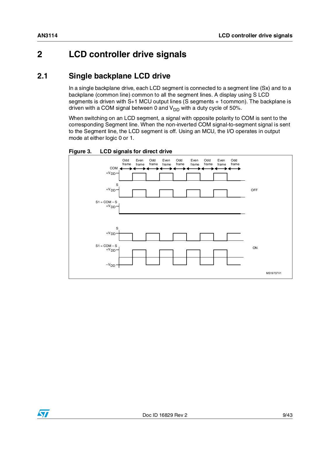
In a single backplane drive, each LCD segment is connected to a segment line (Sx) and to a backplane (common line) common to all the segment lines. A display using S LCD segments is driven with S+1 MCU output lines (S segments + 1common). The backplane is driven with a COM signal between 0 and VDD with a duty cycle of 50%.

When switching on an LCD segment, a signal with opposite polarity to COM is sent to the corresponding Segment line. When the non-inverted COM signal-to-segment signal is sent to the Segment line, the LCD segment is off. Using an MCU, the I/O operates in output mode at either logic 0 or 1.

Figure 3. LCD signals for direct drive

/DD

%VEN

/DD

%VEN

/DD

%VEN

/DD

%VEN

/DD

FRAME

FRAME

FRAME

FRAME

FRAME

FRAME

FRAME

FRAME

FRAME

#/-6$$

3

6$$

3 #/- n 36$$

3

6$$

3 #/- n 36$$

n6$$

/&&

/.

-3 6

Doc ID 16829 Rev 2

9/43

LCD controller drive signals

AN3114


Discrimination ratio calculation for the single backplane LCD:

COM - S [ON] = (0-VDD) +(VDD-0) = 0 => VDC = 0

COM - S [OFF] = (0-0) + (0-0) = 0 => VDC = 0


V(Si)2

(–VDD)2 + (VDD)2

VON(RMS) =

n

=

----------n---------

-------------------

------2------

-------------------- = VDD


V(Si)2

(0)2

+ (0)2

VOFF(RMS) =

n

=

----------n--------

-------------

-------------- = 0


2

D VON(RMS) VDD

= ---------------------------- = ------------ =

VOFF(RMS) 0

2.2Duplex LCD drive

In a duplex drive, two backplanes are used instead of one. Each LCD segment line (Sx) is connected to two LCD segments, which other side is connected to one of the two backplanes or common lines (refer to Figure 4). Thus, only (S/2)+2 MCU pins are necessary to drive an LCD with S segments.

Three different voltage levels have to be generated on the backplanes: 0, VDD/2 and VDD. The Segment line voltage levels are 0 and VDD only. Figure 5 shows typical backplane, segment lines and LCD waveforms. The intermediate voltage VDD/2 is only required for the backplane voltages. When one backplane is active (0 V during an odd frame and VDD during an even frame), the other is inactive (VDD/2).

Figure 4. Basic segment lines connection in duplex mode


3


3


3


3


3 3


3


#/-

#/-

AI

10/43

Doc ID 16829 Rev 2

AN3114


LCD controller drive signals


Figure 5. LCD signals for duplex mode


/DD

%VEN

/DD

%VEN

/DD


FRAME

FRAME

FRAME

FRAME

FRAME


6$$


#/-


6$$


6


#/-


6$$


6$$


6


6$$


3%'


6


6$$


3%'


6


6$$


#/- 3%'


6$$


6


3ELECTED WAVEFORM


6

$$


6

$$


-3 6

Discrimination ratio calculation for duplex mode:

COM0 - SEG0 [ON] = (0 - VDD) + (VDD/2 - VDD) + (VDD - 0) + (VDD/2 - 0) => VDC = 0 COM0 - SEG0 [OFF] = (0 - 0) - (VDD/2 - VDD) + (0 - 0) + (VDD/2 - 0) => VDC = 0


V(Si)2


2


VDD 2


VDD 2


2


(VDD) +


+ (–VDD)


VON(RMS) =

n

=


---

--

2-------


+ -------2--------


----------

---

-------------

---------

------

--

---

---

--------

------

----4-----

--------

----

--------

-----------------

-------------

---- = 0.790VDD


n


V(Si)2


2


VDD

2


2


VDD 2


(0) +


+ (0)


VOFF(RMS) =

n


------2-----

-


+

-------2--------


----------n-----------


= ---

---------

------

--

---

---

--------

------

------4-----------

----

--------

-----------------

------- = 0.353VDD


D =

VON(RMS)


=

0.790VDD

= 2.237


V-----OFF----------(--RMS-----------)


0.353VDD----------------------------


Doc ID 16829 Rev 2

11/43

LCD controller drive signals

AN3114


2.3Quadruplex LCD drive

In a quadruplex LCD drive, four backplanes are used. Each LCD pin is connected to four LCD segments, which other side is connected to one, two or four backplanes. Consequently, only (S/4)+4 MCU pins are necessary to drive an LCD with S LCD segments (pixels). For example, to drive an LCD with 112 LCD segments (28 ×4), only 32 I/O ports are required (28 I/O ports to drive the segment lines and 4 I/O ports to drive the backplanes).

Four different voltage levels have to be generated on the common lines: 0, VDD/3, 2VDD/3 and VDD. The Segment line voltage levels are also 0, VDD/3, 2VDD/3 and VDD. The LCD segment is inactive if the RMS voltage applied is below the LCD threshold voltage Vth, and is active if the LCD RMS voltage is above the threshold. Figure 7. shows typical backplane, Segment lines and LCD waveforms. The intermediate voltage VDD/3 and 2VDD/3 are required for backplane voltages. When a backplane or COM is active (0 V during an odd frame and VDD during an even frame), the others are made inactive by applying to them 2VDD/3 during an odd frame and VDD/3 during an even frame.

Figure 6. Basic LCD segment lines connection in quadruplex mode

3

3

3


3 3 3 3

#/-

#/-

#/-

#/-

AI

12/43

Doc ID 16829 Rev 2

ST AN3114 Application note

AN3114

LCD controller drive signals


Figure 7. LCD signals in quadruplex mode

/DDDFRAME %VEN FRAME

#/-

#/-

#/-

#/-

3%'

3%'

#/- 3%' 3ELECTED WAVEFORM

6$$6$$ 6$$6

6$$6$$ 6$$6

6$$6$$ 6$$6

6$$6$$ 6$$6

6$$6$$ 6$$6

6$$6$$ 6$$6

6$$6$$ 6$$66$$

6$$6$$

-3 6

Doc ID 16829 Rev 2

13/43

Loading...
+ 30 hidden pages