

Page 1

AN3110
Application note
Using the STVM100
to automatically adjust VCOM voltage in e-paper
Introduction
The widespread use of multimedia electronic devices, coupled with environmental concerns
over the manufacturing and use of traditional paper products, provide the opportunity for the
utilization of electronic paper (e-paper).
Electronic paper is the best replacement for conventional paper. A high-quality image can
be displayed for weeks without power. Energy is consumed only during the short refresh
time. Unlike its counterpart, liquid crystal display (LCD) devices, e-paper does not require a
backlight, which not only saves energy, but also makes reading more comfortable.
Achieving high-quality images on e-paper requires the correct setting of the VCOM voltage
on the PC board. STMicroelectronics offers the STVM100 VCOM calibrator which is ideal
for e-paper applications and allows the VCOM voltage to be set automatically. In this
application note, the e-paper principle is briefly described so that the user can understand
the necessity of an accurate VCOM voltage setting and how the STVM100 can be used for
this purpose.
January 2010 Doc ID 16799 Rev 1 1/10
www.st.com
Page 2
General principle of e-paper AN3110
1 General principle of e-paper
Using Electrophoretic Display (EPD) technology, pre-charged particles within the capsules
can be either driven to the top plate (common electrode) of the e-paper which is white due to
the reflection of the light, or driven to the bottom plate (column electrodes) of the paper
which is dark. The particles are in a bi-stability state so that the position can be maintained
even though there is no power applied to the e-paper.
Similar to liquid crystal display (LCD) devices, some of the EPD devices are also formatted
by pixels with the active matrix controlled using TFT (Thin-Film Transistor) technology.
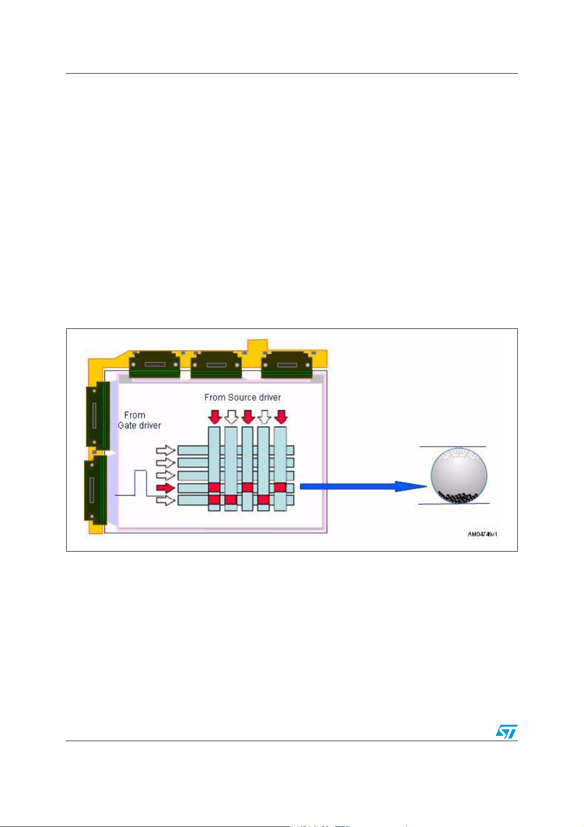
In Figure 1, the gate driver sends a line selection pulse to the top line and turns on the first
line TFT. The data (analog voltage) is transferred from the source driver to the pixels in the
first line. After the first line data is updated, the gate driver selects the second line and then
the third, and so on. Once the last line has been scanned, the entire picture on the screen
has been updated (whole e-paper refresh). Then the gate driver begins again from the first
line and starts the next refresh if required. The line selection pulse pattern is configurable in
the gate driver.
Figure 1. E-paper display layout
2/10 Doc ID 16799 Rev 1
Page 3
AN3110 General principle of e-paper
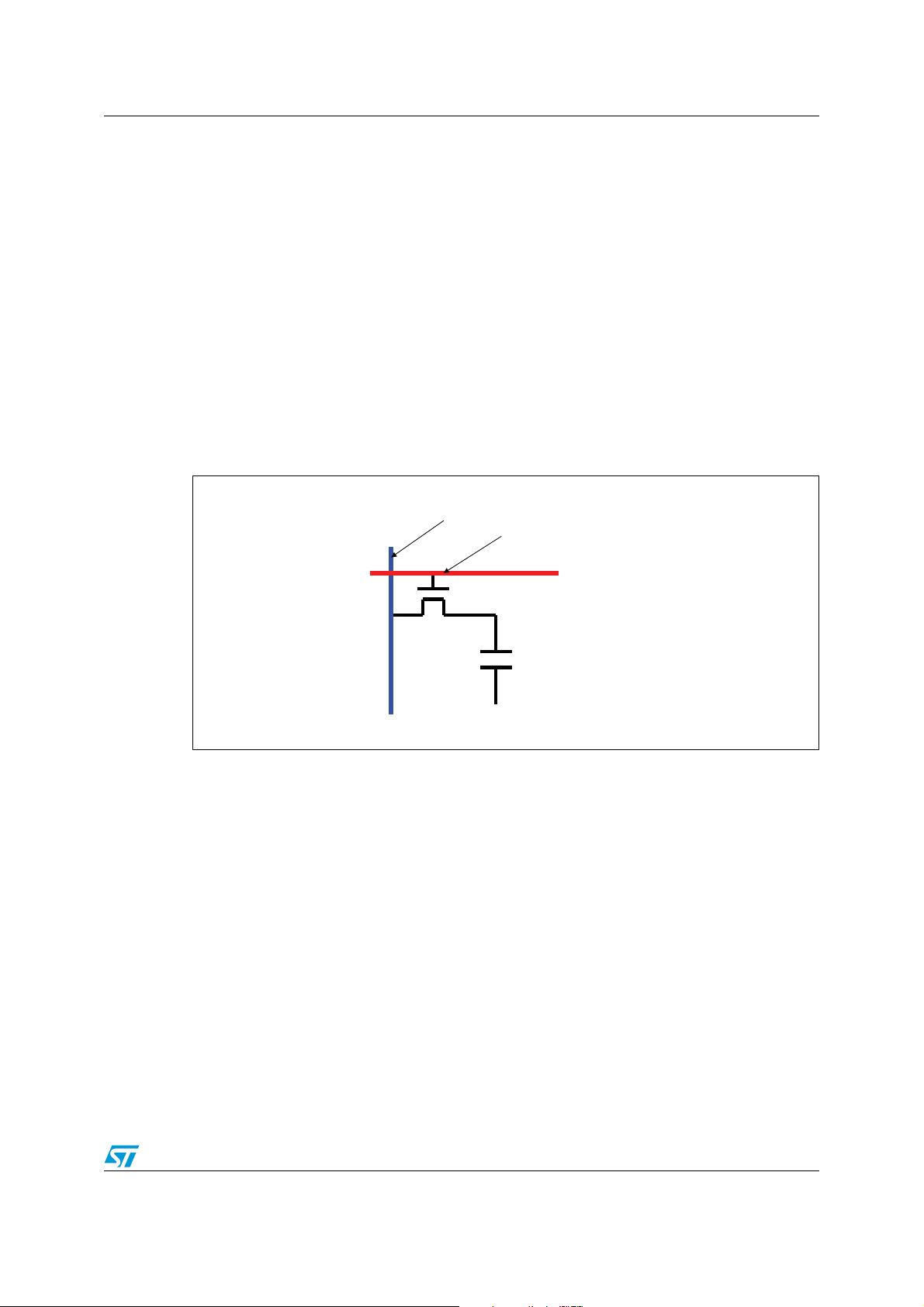
Figure 2 shows the detailed pixel schematic. The Cep is the equivalent capacitance of the e-
paper. The position of the pre-charged particles in the capsules between the two electrodes
depends on the absolute voltage applied on the electrodes.
The common electrodes of all the pixels are connected together and a constant Vcommon
voltage (VCOM) is required to drive this electrode. The VCOM voltage should be set
correctly panel-by-panel for the best performance. Residual pixels (“ghosting” effect) will
appear after content refresh if the VCOM voltage is not set correctly.
After the line is selected by the gate driver, the corresponding column electrode is
connected to the source driver by the TFT. When the source driver supplies positive voltage
to the column electrodes, the positively-charged particles are repelled by the positive
electric field and moved to the top plate of the capsule. The white particles are reflective and
reflect the ambient light to the viewer so that this pixel is viewed white. Otherwise, if
negative voltage is supplied to the column electrode, the positively-charged particles are
attracted to the negative electric field and moved towards the bottom side of the capsule
which then appears dark.
Figure 2. Basic e-paper pixel schematic
To source driver
To gate driver
TFT
Column electrode
C
ep
Common electrode
AM04747v1
Doc ID 16799 Rev 1 3/10
Page 4

E-paper VCOM calibration using the STVM100 AN3110
2 E-paper VCOM calibration using the STVM100
The VCOM values vary according to the type of e-paper. Each of the VCOM values is well
tested and provided by the e-paper manufacturer who normally labels the e-paper PC board
with a barcode and a decimal value. The common distribution range is from –0.5 V to
–2.5 V, but this range varies according to the technology.
The digital VCOM calibrator STVM100 (see datasheet at www.st.com) can completely
replace the mechanical potentiometer as an automatic, more accurate, and robust solution.
The STVM100 provides a digital I
output drives an external resistive voltage divider, which can then be applied to an external
VCOM buffer (TS512, precision dual operational amplifier). Four external resistors R1, R6,
R7 and R12 determine the highest and lowest value of the VCOM. An increase in the output
sink current lowers the voltage on the external divider so that the VCOM can be adjusted by
128 steps within this range. Once the desired VCOM setting is achieved, it can be stored in
the internal EEPROM that is automatically recalled during each power-up. Figure 3 shows
the basic connection of the STVM100 in e-paper applications.
Figure 3. STVM100 and VCOM buffer (TS512 from ST) on e-paper PC board
2
C interface to control the sink current output (I
+15V
OUT
). This
R7
14K
-15V
R1
80.6K
R6
28K
R12
100K
R9
0
R2
0
TP 8
TP 5
VCOM-
-15V
VCOM+
1
2
3
TP 6
VCOM- BUFVset
U2
1OUT
VDD+
1IN1IN +
VDD-42IN +
TS512
2OUT
2IN-
8
7
6
5
AM04748v1
+3V3
R15
0
R14
0
Not mounted
GND
+3V3
SDA
SCL
U1
6
7
3
STVM100
VDD5AVDD
Vout
SDA
Vset
SCL
GND
WP
2
1
8
4
GND
In this example, by choosing 1% accuracy resistors of R1, R6, R7 and R12 with a supply of
±15 V, a range of –0.5 V to – 2.5 V can be obtained at point VCOM– by writing 0 to 127 to
the STVM100 through the I
2
C bus. The VCOM– is buffered by the TS512 to VCOM– BUF
which is applied to the VCOM plate of the e-paper.
The advantages of this circuit are:
● The STVM100 replaces the conventional variable resistor (VR). The STVM100 is
robust, accurate, easily configurable, and provides automatic adjustment capability.
● The TS512 supports ±18 V (here ±15 V is used) which is necessary in e-paper
applications.
● No additional supply is required, making the power management circuit design easier.
+15V
4/10 Doc ID 16799 Rev 1
Page 5

AN3110 STVM100 auto-adjustment demonstration kit
3 STVM100 auto-adjustment demonstration kit
Since the target VCOM value is given by a decimal value or by a barcode on the
manufacturer’s e-paper PC board, ST has also developed an auto-adjustment
demonstration kit to facilitate calibration.
Only four single wires are needed to connect the e-paper PC board and the adjustment kit,
and the user can input the target VCOM value either manually or by a barcode reader in the
GUI as shown in Figure 4. After a single click on the "Run" button, no more than 1 second
later, the target VCOM is correctly adjusted and appears in the "Final VCOM" text box. In
this GUI, single-step up/down buttons are also available for the user to do a simple
comparison and confirmation of the VCOM value.
Figure 4. VCOM auto-adjustment kit GUI
AM04749v1
Doc ID 16799 Rev 1 5/10
Page 6

Auto-adjustment demonstration kit test results AN3110
4 Auto-adjustment demonstration kit test results
Tab l e 1 gives an example of the lab test results of the auto-adjustment kit.
It can be seen that this board has a maximum 11 mV difference between the target VCOM
write and the actual measured on VCOM– BUF. The results demonstrate its suitability for
the e-book VCOM application.
Please contact local ST sales office for the availability of the demonstration board hardware
and software.
Table 1. Test results of the auto-adjustment kit
Target voltage
for VCOM– BUF (V)
–0.65 –0.657 –0.007
–0.75 –0.757 –0.007
–0.85 –0.852 –0.002
–0.95 –0.95 0
–1 –0.998 0.002
–1.1 –1.096 0.004
–1.2 –1.193 0.007
–1.3 –1.29 0.01
–1.4 –1.404 –0.004
–1.5 –1.5 0
–1.51 –1.5 0.01
–1.52 –1.517 0.003
–1.53 –1.533 –0.003
–1.54 –1.533 0.007
–1.55 –1.549 0.001
–1.56 –1.565 –0.005
–1.57 –1.565 0.005
Measured voltage
on VCOM– BUF (V)
Delta between target and
measured voltage
on VCOM– BUF (V)
–1.58 –1.581 –0.001
–1.59 –1.581 0.009
–1.6 –1.597 0.003
–1.7 –1.694 0.006
–1.8 –1.792 0.008
–1.9 –1.889 0.011
–2 –2.003 –0.003
–2.1 –2.1 0
6/10 Doc ID 16799 Rev 1
Page 7

AN3110 Auto-adjustment demonstration kit test results
Table 1. Test results of the auto-adjustment kit (continued)
Target voltage
for VCOM– BUF (V)
–2.2 –2.198 0.002
–2.3 –2.295 0.005
–2.4 –2.393 0.007
–2.5 –2.491 0.009
–2.6 –2.589 0.011
–2.7 –2.691 0.009
Measured voltage
on VCOM– BUF (V)
Maximum error (V) 0.011
Delta between target and
measured voltage
on VCOM– BUF (V)
Note: VCOM– BUF is the point on the demonstration board which connects to the VCOM panel on
the e-book. Please refer to Figure 3 for a detailed description.
Doc ID 16799 Rev 1 7/10
Page 8

Conclusion AN3110
5 Conclusion
The STVM100 VCOM calibrator is ideally suited for the e-paper and e-book display
applications. By taking advantage of its 7-bit, non-volatile common voltage setting
capability, it allows easy and automated configuration of e-book display panels in a
manufacturing environment.
An STVM100 auto-adjustment kit is also available to demonstrate how VCOM accuracy of
better than ±16 mV is easily achievable.
8/10 Doc ID 16799 Rev 1
Page 9

AN3110 Revision history
6 Revision history
Table 2. Document revision history
Date Revision Changes
07-Jan-2010 1 Initial release.
Doc ID 16799 Rev 1 9/10
Page 10

AN3110
Please Read Carefully:
Information in this document is provided solely in connection with ST products. STMicroelectronics NV and its subsidiaries (“ST”) reserve the
right to make changes, corrections, modifications or improvements, to this document, and the products and services described herein at any
time, without notice.
All ST products are sold pursuant to ST’s terms and conditions of sale.
Purchasers are solely responsible for the choice, selection and use of the ST products and services described herein, and ST assumes no
liability whatsoever relating to the choice, selection or use of the ST products and services described herein.
No license, express or implied, by estoppel or otherwise, to any intellectual property rights is granted under this document. If any part of this
document refers to any third party products or services it shall not be deemed a license grant by ST for the use of such third party products
or services, or any intellectual property contained therein or considered as a warranty covering the use in any manner whatsoever of such
third party products or services or any intellectual property contained therein.
UNLESS OTHERWISE SET FORTH IN ST’S TERMS AND CONDITIONS OF SALE ST DISCLAIMS ANY EXPRESS OR IMPLIED
WARRANTY WITH RESPECT TO THE USE AND/OR SALE OF ST PRODUCTS INCLUDING WITHOUT LIMITATION IMPLIED
WARRANTIES OF MERCHANTABILITY, FITNESS FOR A PARTICULAR PURPOSE (AND THEIR EQUIVALENTS UNDER THE LAWS
OF ANY JURISDICTION), OR INFRINGEMENT OF ANY PATENT, COPYRIGHT OR OTHER INTELLECTUAL PROPERTY RIGHT.
UNLESS EXPRESSLY APPROVED IN WRITING BY AN AUTHORIZED ST REPRESENTATIVE, ST PRODUCTS ARE NOT
RECOMMENDED, AUTHORIZED OR WARRANTED FOR USE IN MILITARY, AIR CRAFT, SPACE, LIFE SAVING, OR LIFE SUSTAINING
APPLICATIONS, NOR IN PRODUCTS OR SYSTEMS WHERE FAILURE OR MALFUNCTION MAY RESULT IN PERSONAL INJURY,
DEATH, OR SEVERE PROPERTY OR ENVIRONMENTAL DAMAGE. ST PRODUCTS WHICH ARE NOT SPECIFIED AS "AUTOMOTIVE
GRADE" MAY ONLY BE USED IN AUTOMOTIVE APPLICATIONS AT USER’S OWN RISK.
Resale of ST products with provisions different from the statements and/or technical features set forth in this document shall immediately void
any warranty granted by ST for the ST product or service described herein and shall not create or extend in any manner whatsoever, any
liability of ST.
ST and the ST logo are trademarks or registered trademarks of ST in various countries.
Information in this document supersedes and replaces all information previously supplied.
The ST logo is a registered trademark of STMicroelectronics. All other names are the property of their respective owners.
© 2010 STMicroelectronics - All rights reserved
STMicroelectronics group of companies
Australia - Belgium - Brazil - Canada - China - Czech Republic - Finland - France - Germany - Hong Kong - India - Israel - Italy - Japan -
Malaysia - Malta - Morocco - Philippines - Singapore - Spain - Sweden - Switzerland - United Kingdom - United States of America
www.st.com
10/10 Doc ID 16799 Rev 1
 Loading...