ST AN3093 Application note

AN3093

Application note

ALTAIR05T-800 5 W wide range CV-CC optoless adapter demonstration board

1 Introduction

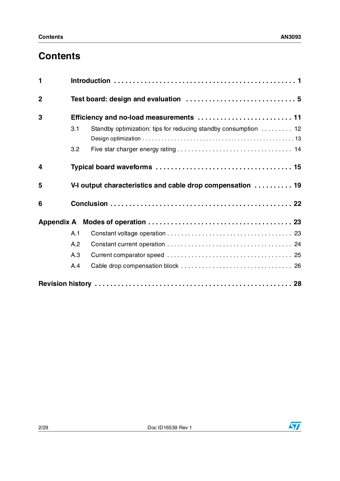
This application note describes the demonstration board of the all primary-sensing switching regulator ALTAIR05T-800 and presents the results of its bench evaluation. The board implements a 5 W (5 V / 1 A) wide range mains battery charger with constant voltage/constant current.

The ALTAIR05T-800 combines a high-performance low-voltage PWM controller chip and an 800 V, avalanche rugged power MOSFET in the same package.

The PWM chip is a quasi-resonant (QR) current mode controller IC specifically designed for QR ZVS (zero-voltage switching at switch turn-on) flyback converters.

The device is capable of providing constant output voltage (CV) and constant output current (CC) regulation using primary sensing feedback. This eliminates the need for the optocoupler, the secondary voltage reference, as well as the current sensor, while maintaining very accurate regulation.

Additionally, it is possible to compensate the voltage drop of the output cable, so as to improve CV regulation on the externally accessible terminals.

Extremely low consumption under no-load conditions is ensured thanks to a controlled burst mode operation that, along with the built-in high-voltage startup circuit and the low operating current of the device, helps minimize residual input consumption. Although an auxiliary winding is required in the transformer to correctly perform CV/CC regulation, the chip is capable of powering itself directly from the rectified mains. This is useful especially during CC regulation, where the flyback voltage generated by the winding drops. However, if ultra low no-load input consumption is required to comply with the most stringent energy saving recommendations, then the device needs to be powered via the auxiliary winding.

Figure 1. Demonstration board picture

January 2011

Doc ID16539 Rev 1

1/29

www.st.com

Contents

AN3093


Contents

1

Introduction . . . . . . . . . . . . . . . . . . . . . . . . . . . . . . . . . . . . . . . . . . . . . . .

. 1

2

Test board: design and evaluation . . . . . . . . . . . . . . . . . . . . . . . . . . . . .

5

3

Efficiency and no-load measurements . . . . . . . . . . . . . . . . . . . . . . . . .

11


3.1

Standby optimization: tips for reducing standby consumption . . . . . . . . .

12


Design optimization . . . . . . . . . . . . . . . . . . . . . . . . . . . . . . . . . . . . . . . . . . . . . . . .

13


3.2

Five star charger energy rating . . . . . . . . . . . . . . . . . . . . . . . . . . . . . . . . .

14

4

Typical board waveforms . . . . . . . . . . . . . . . . . . . . . . . . . . . . . . . . . . . .

15

5

V-I output characteristics and cable drop compensation . . . . . . . . . .

19

6

Conclusion . . . . . . . . . . . . . . . . . . . . . . . . . . . . . . . . . . . . . . . . . . . . . . . .

22

Appendix A Modes of operation . . . . . . . . . . . . . . . . . . . . . . . . . . . . . . . . . . . . . .

23


A.1

Constant voltage operation . . . . . . . . . . . . . . . . . . . . . . . . . . . . . . . . . . . .

23


A.2

Constant current operation . . . . . . . . . . . . . . . . . . . . . . . . . . . . . . . . . . . .

24


A.3

Current comparator speed . . . . . . . . . . . . . . . . . . . . . . . . . . . . . . . . . . . .

25


A.4

Cable drop compensation block . . . . . . . . . . . . . . . . . . . . . . . . . . . . . . . .

26

Revision history . . . . . . . . . . . . . . . . . . . . . . . . . . . . . . . . . . . . . . . . . . . . . . . . . . . . 28

2/29

Doc ID16539 Rev 1

AN3093

List of tables


List of tables

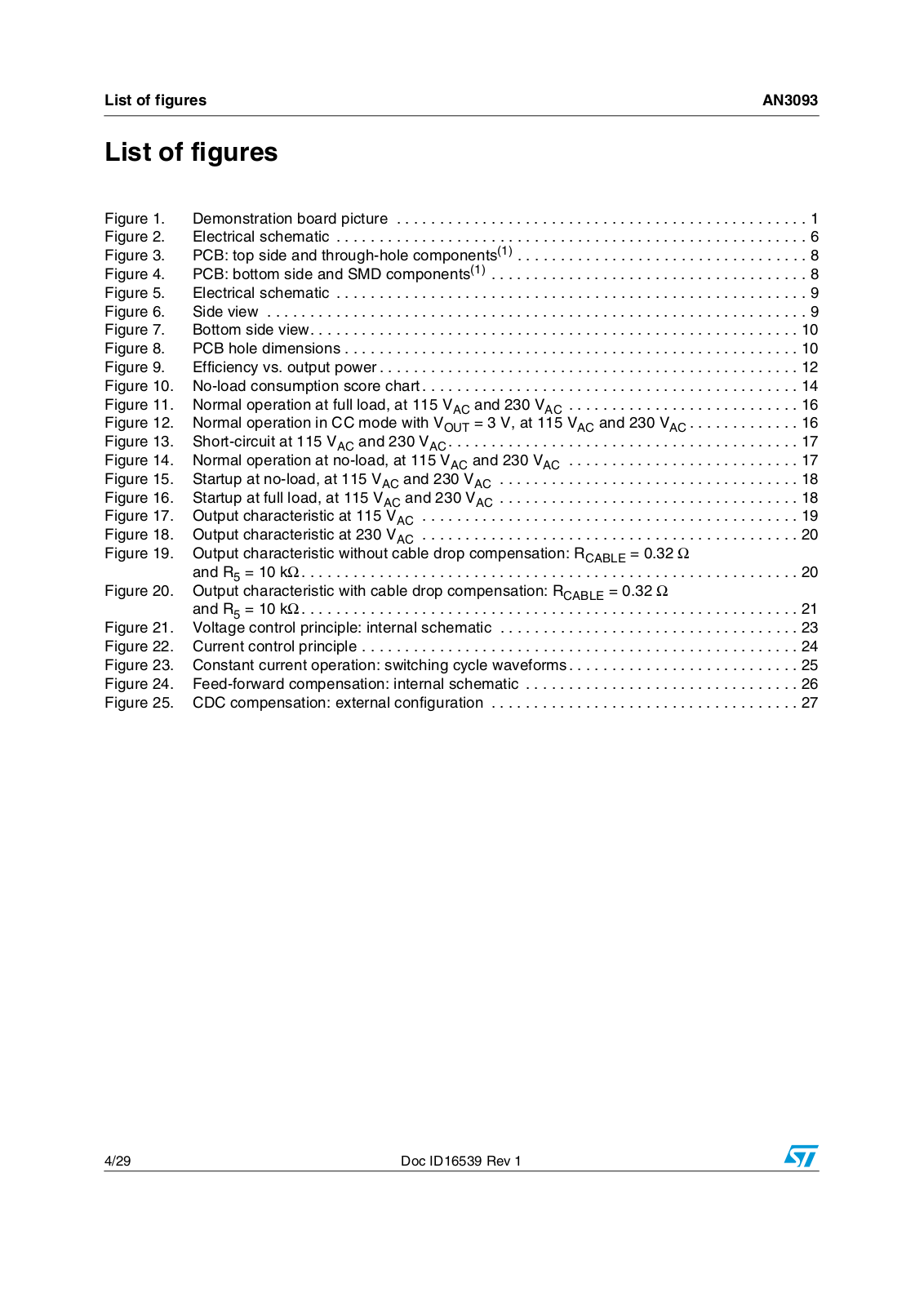
Table 1. ALTAIR05T-800 demonstration board: electrical specification . . . . . . . . . . . . . . . . . . . . . . . 5 Table 2. ALTAIR05T-800 demonstration board: bill of material . . . . . . . . . . . . . . . . . . . . . . . . . . . . . 7 Table 3. ALTAIR05T-800 demonstration board: transformer characteristics . . . . . . . . . . . . . . . . . . . 9

Table 4. Efficiency at 115 VAC . . . . . . . . . . . . . . . . . . . . . . . . . . . . . . . . . . . . . . . . . . . . . . . . . . . . . . . . . . . . . . . . . . . 11 Table 5. Efficiency at 230 VAC . . . . . . . . . . . . . . . . . . . . . . . . . . . . . . . . . . . . . . . . . . . . . . . . . . . . . . . . . . . . . . . . . . . 11

Table 6. Standby consumption . . . . . . . . . . . . . . . . . . . . . . . . . . . . . . . . . . . . . . . . . . . . . . . . . . . . . 12 Table 7. Document revision history . . . . . . . . . . . . . . . . . . . . . . . . . . . . . . . . . . . . . . . . . . . . . . . . . 28

Doc ID16539 Rev 1

3/29

List of figures

AN3093


List of figures

Figure 1.

Demonstration board picture . . . . . . . . . . . . . . . . . . . . . . . . . . . . . . . . .

. . . . . . . . . . . . . .

. 1

Figure 2.

Electrical schematic . . . . . . . . . . . . . . . . . . . . . . . . . . . . . . . . . . . . . . . .

. . . . . . . . . . . . . .

. 6

Figure 3.

PCB: top side and through-hole components(1) . . . . . . . . . . . . . . . . . . .

. . . . . . . . . . . . . .

. 8

Figure 4.

PCB: bottom side and SMD components(1) . . . . . . . . . . . . . . . . . . . . . .

. . . . . . . . . . . . . .

. 8

Figure 5.

Electrical schematic . . . . . . . . . . . . . . . . . . . . . . . . . . . . . . . . . . . . . . . .

. . . . . . . . . . . . . .

. 9

Figure 6.

Side view . . . . . . . . . . . . . . . . . . . . . . . . . . . . . . . . . . . . . . . . . . . . . . . .

. . . . . . . . . . . . . .

. 9

Figure 7.

Bottom side view. . . . . . . . . . . . . . . . . . . . . . . . . . . . . . . . . . . . . . . . . . .

. . . . . . . . . . . . . .

10

Figure 8.

PCB hole dimensions . . . . . . . . . . . . . . . . . . . . . . . . . . . . . . . . . . . . . . .

. . . . . . . . . . . . . .

10

Figure 9.

Efficiency vs. output power . . . . . . . . . . . . . . . . . . . . . . . . . . . . . . . . . . .

. . . . . . . . . . . . . .

12

Figure 10.

No-load consumption score chart . . . . . . . . . . . . . . . . . . . . . . . . . . . . . .

. . . . . . . . . . . . . .

14

Figure 11.

Normal operation at full load, at 115 VAC and 230 VAC . . . . . . . . . . . . .

. . . . . . . . . . . . . .

16

Figure 12.

Normal operation in CC mode with VOUT = 3 V, at 115 VAC and 230 VAC . . . . . . . . . . . . .

16

Figure 13.

Short-circuit at 115 VAC and 230 VAC . . . . . . . . . . . . . . . . . . . . . . . . . . .

. . . . . . . . . . . . . .

17

Figure 14.

Normal operation at no-load, at 115 VAC and 230 VAC . . . . . . . . . . . . .

. . . . . . . . . . . . . .

17

Figure 15.

Startup at no-load, at 115 VAC and 230 VAC . . . . . . . . . . . . . . . . . . . . .

. . . . . . . . . . . . . .

18

Figure 16.

Startup at full load, at 115 VAC and 230 VAC . . . . . . . . . . . . . . . . . . . . .

. . . . . . . . . . . . . .

18

Figure 17.

Output characteristic at 115 VAC . . . . . . . . . . . . . . . . . . . . . . . . . . . . . .

. . . . . . . . . . . . . .

19

Figure 18.

Output characteristic at 230 VAC . . . . . . . . . . . . . . . . . . . . . . . . . . . . . .

. . . . . . . . . . . . . .

20

Figure 19.

Output characteristic without cable drop compensation: RCABLE = 0.32

Ω


and R5 = 10 kΩ . . . . . . . . . . . . . . . . . . . . . . . . . . . . . . . . . . . . . . . . . . . .

. . . . . . . . . . . . . .

20

Figure 20.

Output characteristic with cable drop compensation: RCABLE = 0.32 Ω


and R5 = 10 kΩ . . . . . . . . . . . . . . . . . . . . . . . . . . . . . . . . . . . . . . . . . . . .

. . . . . . . . . . . . . .

21

Figure 21.

Voltage control principle: internal schematic . . . . . . . . . . . . . . . . . . . . .

. . . . . . . . . . . . . .

23

Figure 22.

Current control principle . . . . . . . . . . . . . . . . . . . . . . . . . . . . . . . . . . . . .

. . . . . . . . . . . . . .

24

Figure 23.

Constant current operation: switching cycle waveforms . . . . . . . . . . . . .

. . . . . . . . . . . . . .

25

Figure 24.

Feed-forward compensation: internal schematic . . . . . . . . . . . . . . . . . .

. . . . . . . . . . . . . .

26

Figure 25.

CDC compensation: external configuration . . . . . . . . . . . . . . . . . . . . . .

. . . . . . . . . . . . . .

27

4/29

Doc ID16539 Rev 1

AN3093

Test board: design and evaluation


2 Test board: design and evaluation

A 5 W battery charger demonstration board based on ALTAIR05T-800 is now presented.

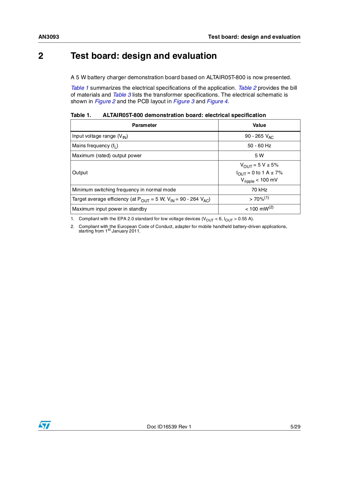
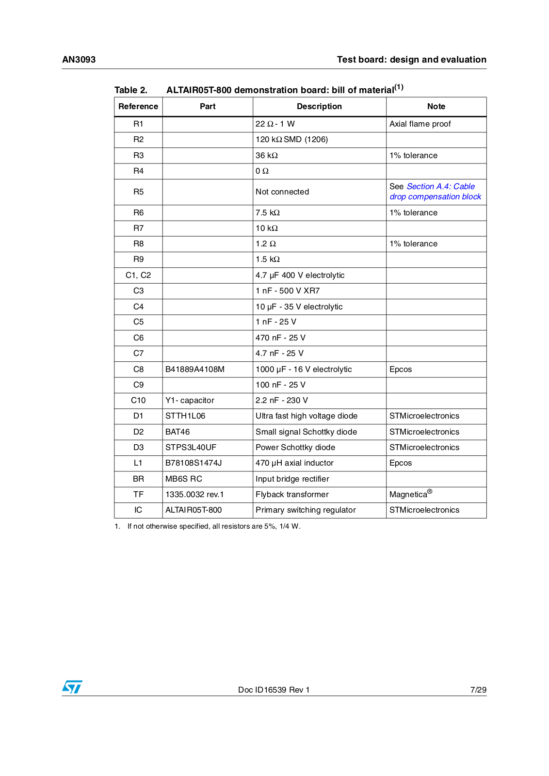
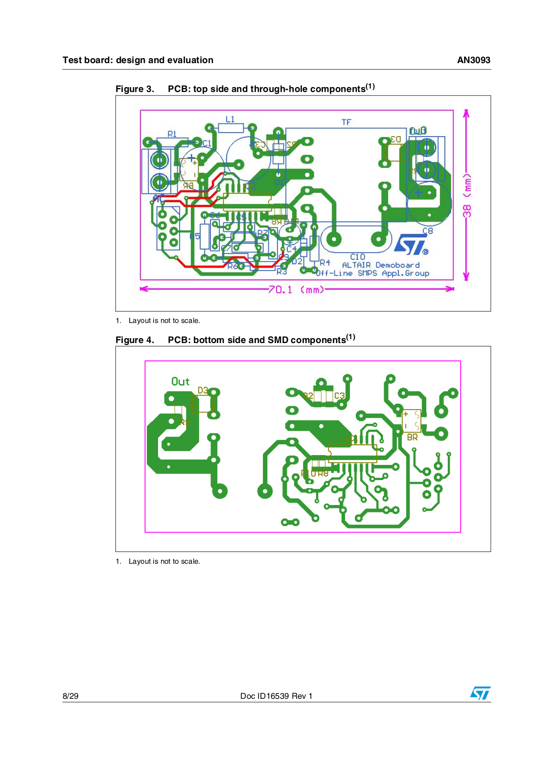
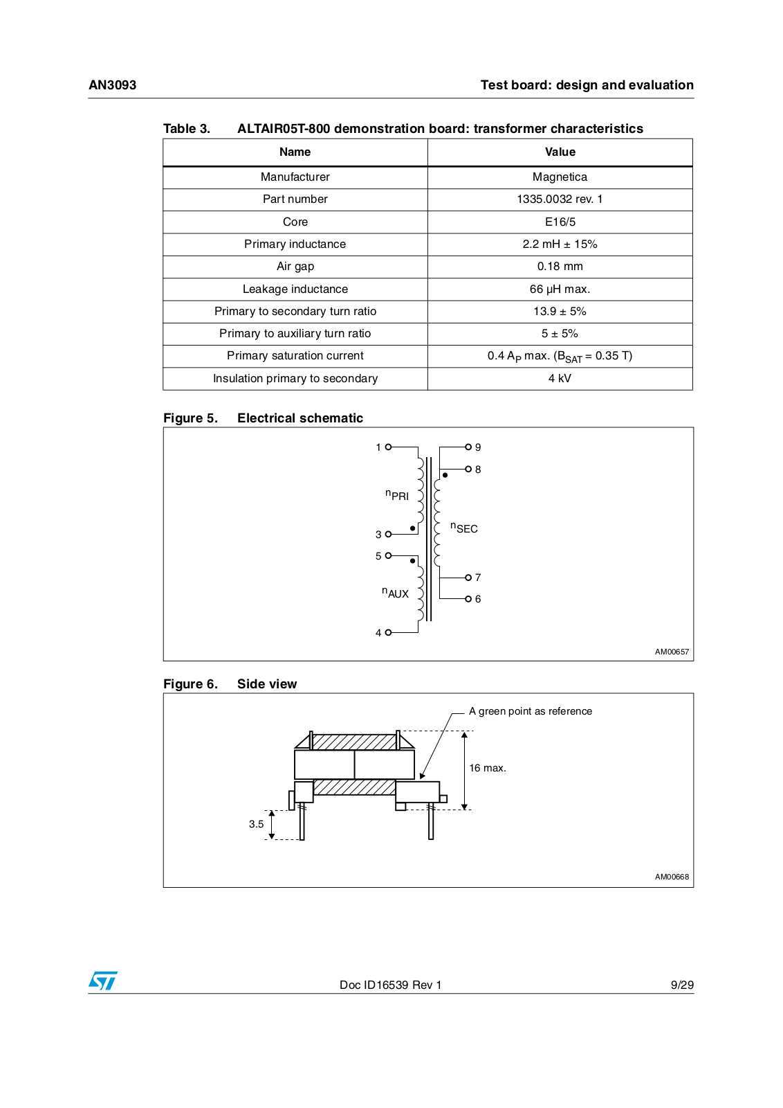
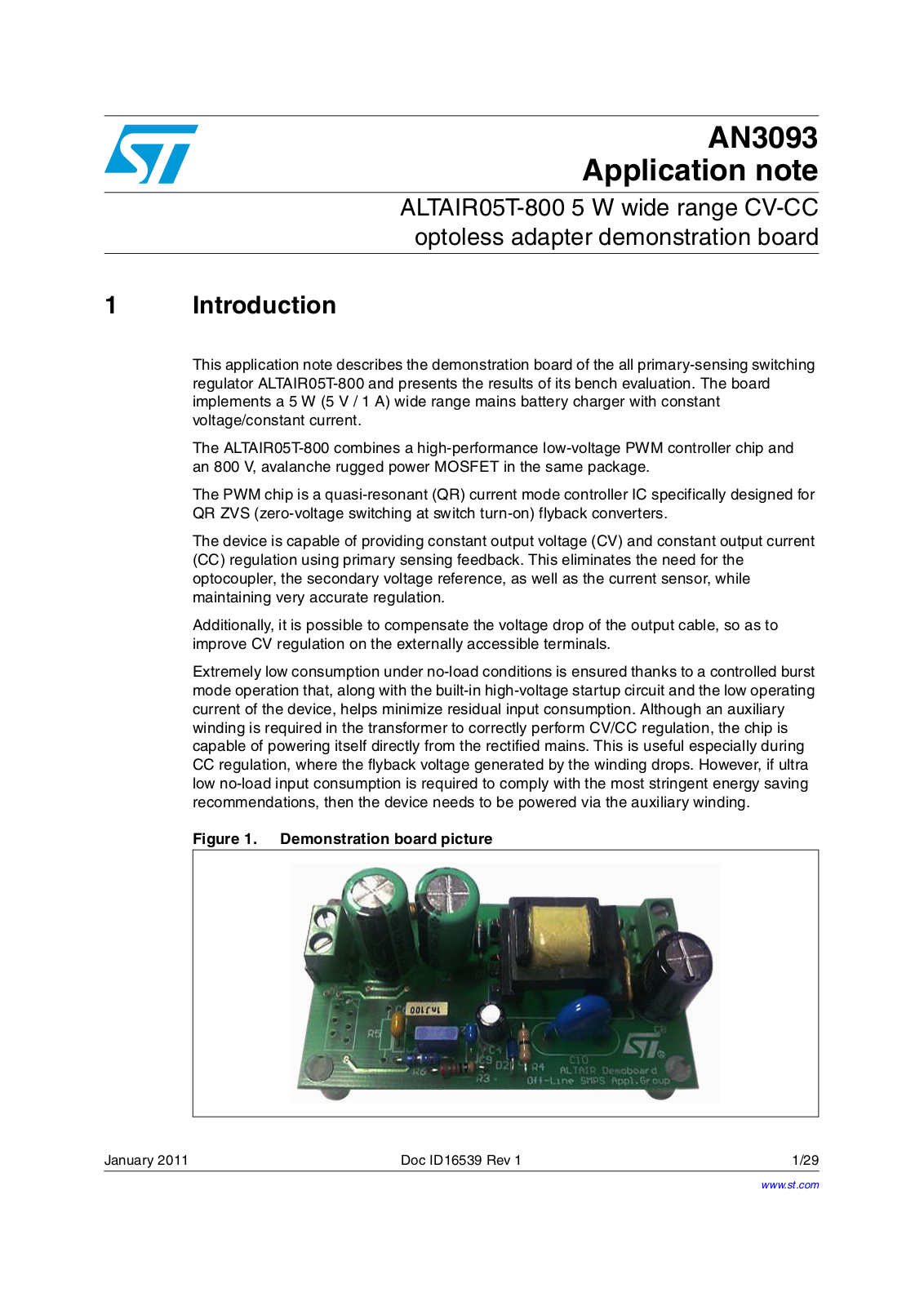
Table 1 summarizes the electrical specifications of the application. Table 2 provides the bill of materials and Table 3 lists the transformer specifications. The electrical schematic is shown in Figure 2 and the PCB layout in Figure 3 and Figure 4.

Table 1.

ALTAIR05T-800 demonstration board: electrical specification


Parameter


Value


Input voltage range (VIN)


90 - 265 VAC

Mains frequency (fL)


50 - 60 Hz

Maximum (rated) output power


5 W


VOUT = 5 V ± 5%

Output


IOUT = 0 to 1 A ± 7%


Vripple < 100 mV

Minimum switching frequency in normal mode

70 kHz


Target average efficiency (at P

OUT

= 5 W, V

IN

= 90 - 264 V )

> 70%(1)


AC


Maximum input power in standby


< 100 mW(2)

1.Compliant with the EPA 2.0 standard for low voltage devices (VOUT < 6, IOUT > 0.55 A).

2.Compliant with the European Code of Conduct, adapter for mobile handheld battery-driven applications, starting from 1st January 2011.

Doc ID16539 Rev 1

5/29

Test board: design and evaluation

AN3093


Figure 2. Electrical schematic


L1


T1

D7

5 V - 1 A


BR


470 µH


STPS3L40UF


AC IN

R1

MB6S-RC


C3

R2


C1


C2


C8


1 nF


R9


4.7 µF

4.7 µF


1000 µF

AC IN

1 W


400 V

400 V


low ESR


D7


STTH1L06


R3


GND


36 kΩ


D2

R4


C9

C4


BAT46


100 nF

10 µF


R5


N.C.


ALTAIR05T-800


C10


CDC


VDD


DRAIN


2.5 V

+


CURRENT


2.2 nF - YCap


CONTROL


FB/ZCD

COMP


IREF

GND

SOURCE


R6


C6


7.5 kΩ


470 nF

C7

R8


C5


R10


R7


4.7 nF


1 nF


1.2

N.C.


AM00656

6/29

Doc ID16539 Rev 1

AN3093


Test board: design and evaluation


Table 2.

ALTAIR05T-800 demonstration board: bill of material(1)


Reference

Part

Description

Note


R1


22 Ω - 1 W

Axial flame proof


R2


120 kΩ SMD (1206)


R3


36 kΩ

1% tolerance


R4


0 Ω


R5


Not connected

See Section A.4: Cable


drop compensation block


R6


7.5 kΩ

1% tolerance


R7


10 kΩ


R8


1.2 Ω

1% tolerance


R9


1.5 kΩ


C1, C2


4.7 µF 400 V electrolytic


C3


1 nF - 500 V XR7


C4


10 µF - 35 V electrolytic


C5


1 nF - 25 V


C6


470 nF - 25 V


C7


4.7 nF - 25 V


C8

B41889A4108M

1000 µF - 16 V electrolytic

Epcos


C9


100 nF - 25 V


C10

Y1capacitor

2.2 nF - 230 V


D1

STTH1L06

Ultra fast high voltage diode

STMicroelectronics


D2

BAT46

Small signal Schottky diode

STMicroelectronics


D3

STPS3L40UF

Power Schottky diode

STMicroelectronics


L1

B78108S1474J

470 µH axial inductor

Epcos


BR

MB6S RC

Input bridge rectifier


TF

1335.0032 rev.1

Flyback transformer

Magnetica®


IC

ALTAIR05T-800

Primary switching regulator

STMicroelectronics


1. If not otherwise specified, all resistors are 5%, 1/4 W.

Doc ID16539 Rev 1

7/29

ST AN3093 Application note

Test board: design and evaluation

AN3093


Figure 3. PCB: top side and through-hole components(1)

1. Layout is not to scale.

Figure 4. PCB: bottom side and SMD components(1)

1. Layout is not to scale.

8/29

Doc ID16539 Rev 1

AN3093


Test board: design and evaluation

Table 3.

ALTAIR05T-800 demonstration board: transformer characteristics


Name


Value


Manufacturer


Magnetica


Part number


1335.0032 rev. 1


Core


E16/5


Primary inductance


2.2 mH ± 15%


Air gap


0.18 mm


Leakage inductance


66 µH max.

Primary to secondary turn ratio


13.9 ± 5%


Primary to auxiliary turn ratio


5 ± 5%


Primary saturation current


0.4 AP max. (BSAT = 0.35 T)

Insulation primary to secondary


4 kV

Figure 5.

Electrical schematic


N02)


N3%#


N!58


!-

Figure 6.

Side view


!!GREEN POINT ASOREFERENCE


MAX

!-

Doc ID16539 Rev 1

9/29

Loading...
+ 20 hidden pages