

Page 1

AN307
APPLICATION NOTE
USE OF TRIACS ON INDUCTIVE LOADS
INTRODUCTION
Although triac circuits are now well known by designers. The use of these components for inductive loads
requires certain precautions which should not be neglected of optimum use is to be made of them. That
is the purpose of this article which reviews the various triac control modes and recalls the principles which
guarantee its correct operation.
Phenomena Occurring when the Circuit is Closed
The triac is known as a component which is essential in controlling power from an AC source (mains). In
most cases, the circuit has an inductive component: either because of the nature of the load itself: motors,
transformers, ballast inductance; or because of the source impedance: utilization of the secondary of a
transformer, length of the supply line, etc. On inductive loads, the operating conditions vary considerably,
when closing the circuit, depending on the control mode (gate current, polarity and width) and synchronization of the firing. In order to build an optimal control circuit it is indispensable to analyse the various possibilities.
FIRING
Control Signal
The triac is fired by a gate current I
holding current value (I
current (di/dt), limited by the load inductance and by the choice of the firing quadrant. The loading current,
I
, is highest in the second quadrant (A2 positive with respect to A1, Ig negative): (see Figure 1-a).
L
The rate of rise of the main current, di/dt, is proportional to the amplitude of the power supply voltage at
the moment of firing (di/dt = V/L). The width of the firing signal required is less when firing occurs near the
peak of the mains voltage than when its occurs around zero of that voltage (see Figure 1-b).
To fire the triac and to ensure conduction in continuous operation, we can compare various types of control
circuits.
Gate Current Control by Single Pulse
To ensure correct operation, the gate pulse should be synchronized with the triac current zero point and
should be long enough to enable the main current to reach the latching current I
In case the pulse occurs before the triac current reaches its zero point (incorrect synchronization) or if its
duration is too short to allow the main current to exceed the latching current I
during alternate half-cycles. The high DC component thus introduced in the load can produce considerable overloads due to saturation of magnetic materials.
). The width of the control signal is determined by the rate of increase of the main
L
> Igt whose duration should enable the main current to reach the triac
g
level (see Figure 2-a).
L
, the triac conducts only
L
REV. 2
1/9March 2004
Page 2
AN307 APPLICATION NOTE
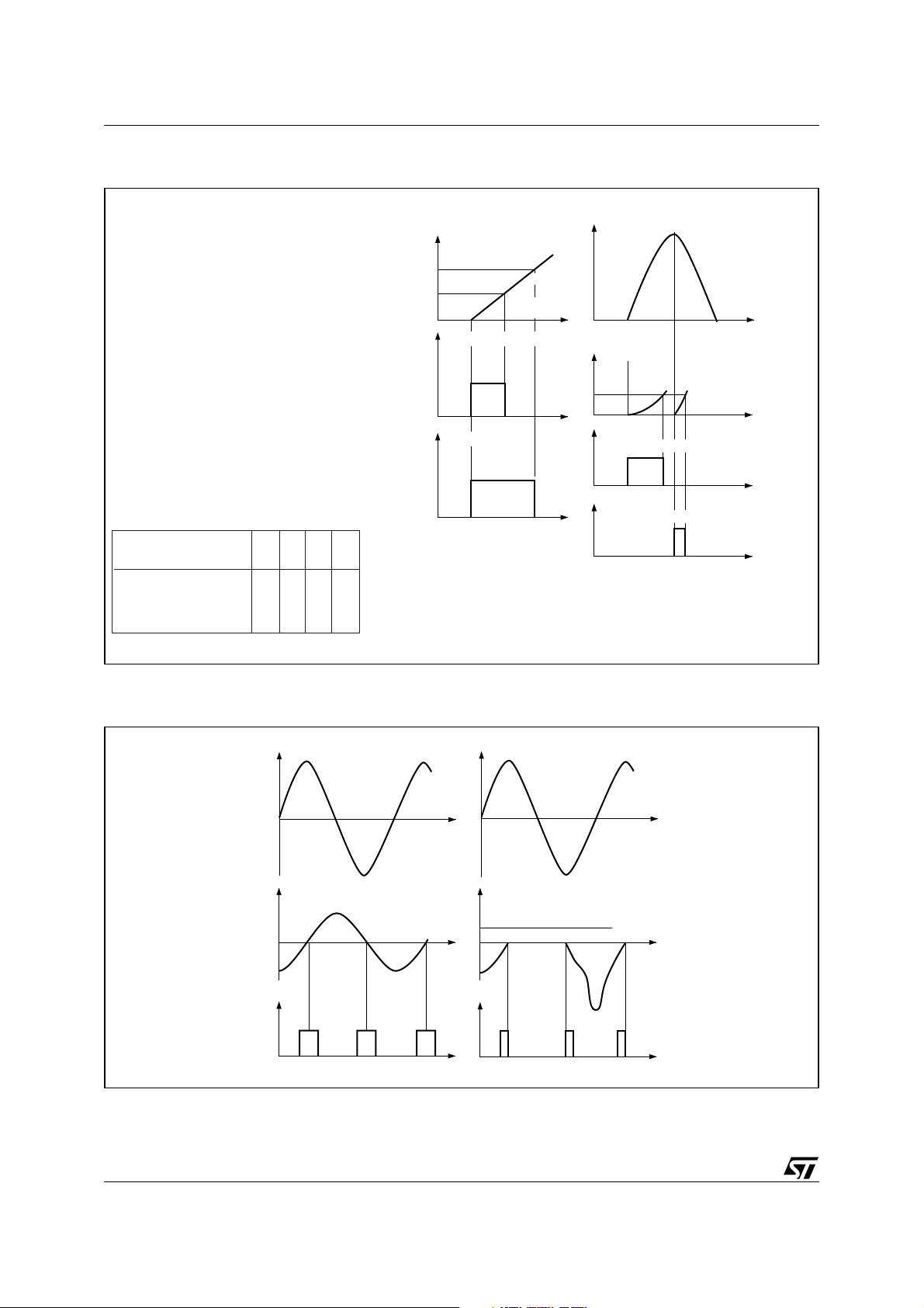
Figure 1. Width of Control Signal Required as a Function of the Firing Quadrant (a); width of
Control Signal Required as a Function of the Moment of Firing (b)
Quadrants
Polarity
A2
G
with respect to A1
I II III IV
++––
+––+
Ittriac current
0
I
quadrants I, III and IV
g
0
I
quadrant III
g
0
IL
quadrant II
IL
quadrants I,
III and IV
Vtmains voltage
0
triac current
I
0
t
I
g
firing at zero voltage
I
g
t
firing at peak voltage
0
t
t
t
ba
Figure 2. Gate Control by a Single Pulse Synchronized with Zero Current (a); in Case of a Single
Pulse whose Duration is too Short, the Triac only Conducts during Alternate Half-cycles (b)
Vtmains voltage
0
Ittriac current
0
I
g
0
Vtmains voltage
0
Ittriac current
IL
0
I
g
0
t
t
2/9
Page 3
AN307 APPLICATION NOTE
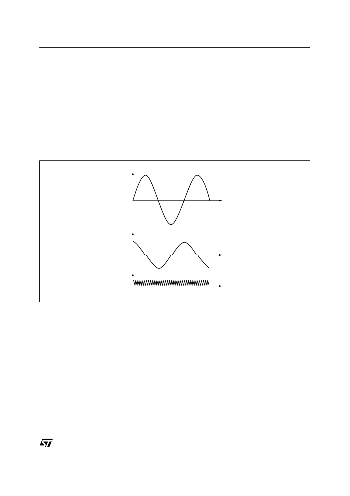
Gate Control by Pulse Train
The control by gate pulse train eliminates problems of synchronization on the current. A recurrence frequency of several kilohertz guarantees correct operation of this type of control (see Figure 3).
This procedure, whose results are satisfactory, is often used for controlling triacs in inductive circuits. A
variant of this principle consists in making use of a circuit which monitors firing and which delivers pulses
to the gate as long as the voltage across the triac is higher than a threshold, usually fixed at about 10 volts
(see Figure 4). This type of circuit enables delivering just the amount of gate current required for firing.
Gate Control by DC Current
Gate control by DC guarantees ideal firing but has the disadvantage of high consumption, specially when
the control power supply is provided by the mains. In this case, it is preferable to use a negative current
for the gate control (quadrants II and III).
Figure 3. Gate Control by Pulse Train
Vtmains voltage
0
I
triac current
0
I
g
0
t
t
TRANSIENT PHENOMENA DURING TRIGGERING
Principles
During continuous operation, the magnetic field H, proportional to the current in the coil, varies with respect to the induction B, with a delay as shown by the hysteresis cycle in Figure 5. In transient operation,
the induction can follow a different path and reach the saturation value BS for which the magnetic field H
(according to the coil current) increases very rapidly (see Figure 8).
In the circuits controlled by a triac, opening occurs when the current is at zero. The induction thus has a
remanent value Br, corresponding to H = 0 (see Figure 5). When the triac begins to conduct, the transients
depend on the instant of synchronization of the control signal with respect to the mains voltage.
3/9
Page 4

AN307 APPLICATION NOTE
Figure 4. Firing Monitoring Circuit: the Control Signal is repeated until Firing
I
triac current
I
g
Firing
monitoring
Threshold
Vz
Control
0
V
Vz
0
I
g
0
Vz
t
t
t
Figure 5. Magnetic Field H with Respect to Induction B in Continuous Sinusoidal Phase
B
B
n
B
r
R
Q
0
B
r
S
B
P
n
HH
n
4/9
Page 5

Figure 6. Induction Bs Versus Field H Variation
B
B
n
B
r
AN307 APPLICATION NOTE
0
H = k · nI
H
FIRING AT ZERO MAINS VOLTAGE
Peak induction tends to the value:
B
= 2 Bn + Br,
max
thus in most cases reaching saturation induction B
.
s
The amplitude of the current proportional to the magnetic field H becomes very high; this type of control
produces the highest transient overloads (See Figure 7-a).
In order to limit the over current during firing at zero voltage, control must be done by complete periods.
Since the triac allows an integral number of half-cycles to pass, the polarity of the mains voltage at the
moment of firing is the reverse of that at the moment the circuit is opened.
Peak induction thus reaches the value:
B
= 2 Bn – Br, because B rises between P and Q on the hysteresis cycle.
max
The overload is lower than previously but still remains high (See Figure 7-b).
FIRING AT PEAK MAINS VOLTAGE
Peak induction takes the value:
B
= Bn + Br.
max
In general, the threshold of saturation B
is not reached and amplitude of the current remains within ac-
s
ceptable limits (See Figure 7-c).
This type of synchronization is simple and efficient and should be adopted whenever possible on loads
composed of materials which can be saturated.
5/9
Page 6

AN307 APPLICATION NOTE
Figure 7. Transient Induction and Current at Beginning of Conduction
Vtmains voltage
0
2 Bn + B
Btinduction
B
s
0
I
triac current
Vtmains voltage
0
r
Btinduction
B
s
0
I
triac current
2 Bn – B
r
Vtmains voltage
0
Btinduction
B
s
0
I
triac current
Bn + B
r
A :
firing at voltage zero
B :
firing at voltage zero
conduction by complete periods
t
C : firing at voltage peak
t
FIRING AT INDUCTANCE PHASE SHIFT WITH CONDUCTION BY COMPLETE PERIODS
Firing at the real inductance phase shift with conduction by complete periods places the magnetic field
and the induction on the hysteresis cycle of continuous operation: consequently, transients are eliminated.
However, the design of the control circuit for this firing mode is complex and consequently it is reserved
for special applications.
FIRING BY PHASE SWEEP
The triac is first fired at the end of a half-cycle. Then progressively the difference of phase between the
voltage zero and the instant of firing decreases until total conduction. With a sufficiently low sweep speed,
any transient overload is thus avoided (see Figure 8). This procedure is widely used and gives very good
results.
6/9
Page 7

Figure 8. Firing by Phase Sweep
V mains voltage
AN307 APPLICATION NOTE
0
I triac current
0
I
g
0
t
t
t
SPURIOUS FIRING
The control circuit plays an important role in normal operation. However, in case of spurious firing, the triac
may have to withstand an accidental overload. The peak amplitude of the current which could flow through
the triac should be known to select its rating: the maximum current which could flow through the circuit
should not be higher than the accidental overload capacity of the triac (ITSM). In this care the triac is oversized.
CONCLUSION
We have seen the essential points guaranteeing correct operation of a triac. If the circuit is closed on an
inductive load, you need to:
Fire the triac: With a sufficiently wide gate control signal, in the chosen quadrants (depending on whether higher sensitivity or a low latching current is required).
Avoid transient overloads: By synchronizing the control signal with respect to the mains at the moment
of firing (firing of the triac at zero voltage should be avoided).
Keep the triac in conduction: By selection of the type of control (avoid gate control by a single short
pulse).
7/9
Page 8

AN307 APPLICATION NOTE
REVISION HISTORY
Table 1. Revision History
Date Revision Description of Changes
February-1989 1 First Issue
31-Mar-2004 2 Stylesheet update. No content change.
8/9
Page 9

AN307 APPLICATION NOTE
Information furnished is believed to be accurate and reliable. However, STMicroelectronics assumes no responsibility for the consequences
of use of such information nor for any infringement of patents or other rights of third parties which may result from its use. No license is granted
by implication or otherwise under any patent or patent rights of STMicroelectronics. Specifications mentioned in this publication are subject
to change without notice. This publication supersedes and replaces all information previously supplied. STMicroelectronics products are not
authorized for use as critical components in life support devices or systems without express written approval of STMicroelectronics.
The ST logo is a registered trademark of STMicroelectronics.
All other names are the property of their respective owners
© 2004 STMicroelectronics - All rights reserved
STMicroelectronics GROUP OF COMPANIES
Australia - Belgium - Brazil - Canada - China - Czech Republic - Finland - France - Germany - Hong Kong - India - Israel - Italy - Japan -
Malaysia - Malta - Morocco - Singapore - Spain - Sweden - Switzerland - United Kingdom - United States
www.st.com
9/9
 Loading...