

Page 1
AN302
Application note
Thyristors and TRIACs: holding current - an important parameter
Introduction
The purpose of this note is to familiarize the users of TRIACs or thyristors with the
hypostatic current parameter, I
The importance of this parameter is illustrated by some typical examples. Then a description
is given of how to measure it and on its variation with the conditions of use and the
sensitivity of the components.
This application note discusses only the TRIAC; however, the concepts are also valid for
SCRs.
Definition
To keep an electromechanical relay turned on, it is necessary to have a minimum current
circulating in its coil. If the current falls too low the relay would turn off. The same
phenomenon can be observed in a TRIAC. This minimum current which keeps the TRIAC
conducting is called the hypostatic or holding current, I
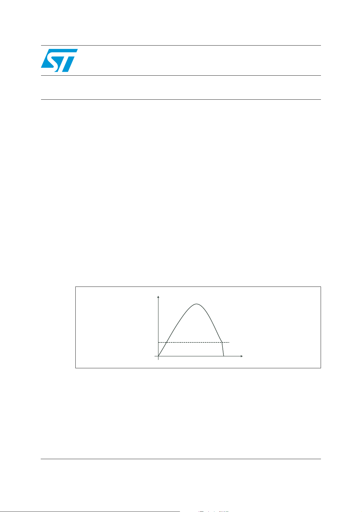
Figure 1 below shows the holding current and the gate current pulse, I
the basic TRIAC circuit. After the TRIAC is turned on, a current, I
TRIAC current falls below the holding current the TRIAC is blocked and requires another
gate pulse before it can turn on again.
, also known as the holding current parameter.
H
. (see Figure 1).
H
, which is applied to
G
, flows through it.When the
T
Figure 1. Current control
I
I
T
T
I
I
H
H
t
t
March 2008 Rev 3 1/10
www.st.com
Page 2
Application examples AN302
1 Application examples
The importance of the holding current is highlighted by the following application examples.
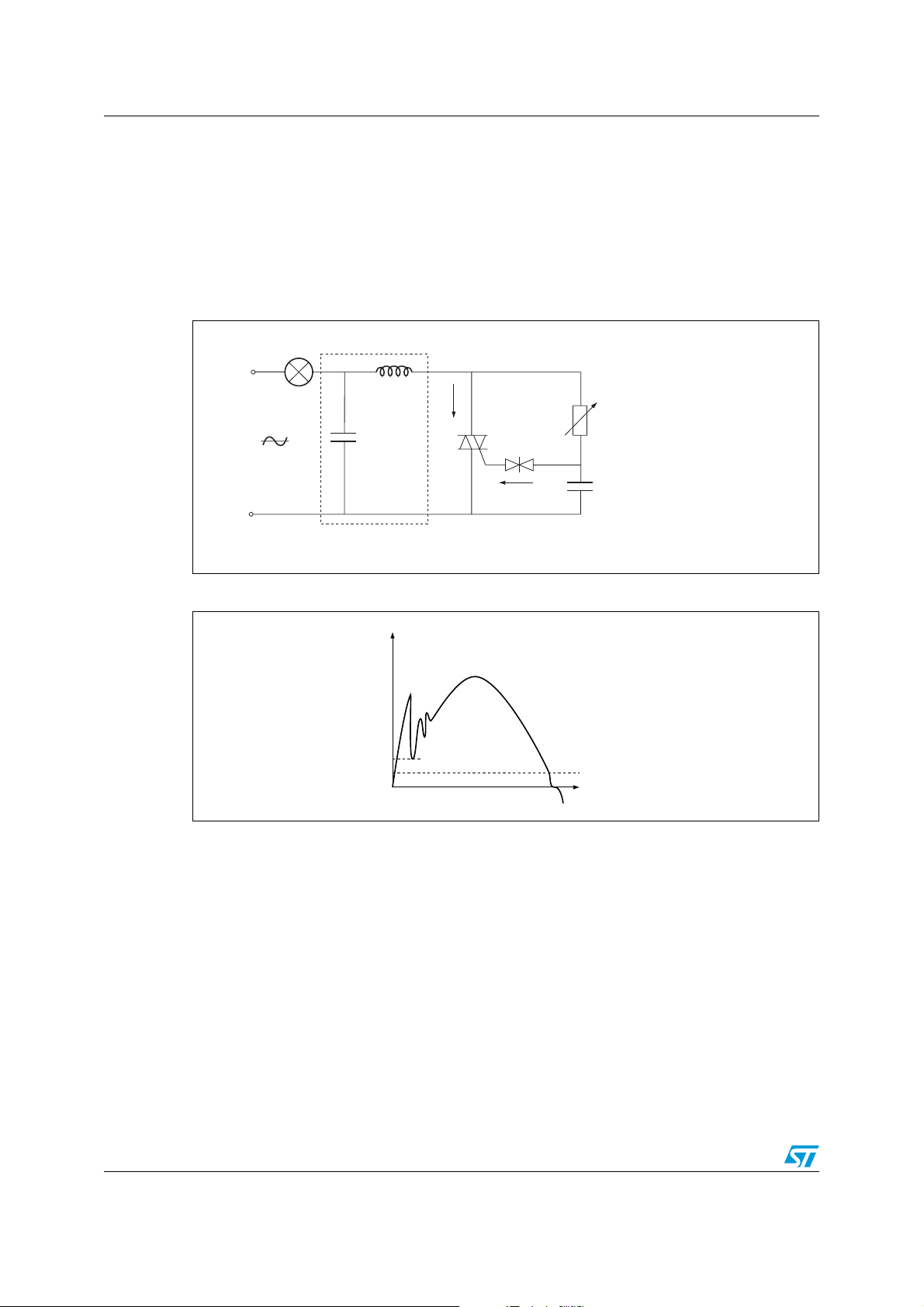
1.1 Example 1: light dimmer
Figure 2. Dimmer with interference suppression filter (coil and capacitor)
Load
L
I
T
220V
C
Interference suppression
LC filter
Tr i ac
I
G
RC phase-shift network
Figure 3. Current in the dimmer TRIAC
I
T
I
O
I
H
t
In the dimmer circuit of Figure 2 the interference suppression filter can produce oscillations.
If the minimum current during these oscillations is higher than the holding current, that is, if
I
in Figure 3, the TRIAC remains turned on. But if IO falls below IH, the TRIAC will be
O>IH
blocked.
It is possible, if the coil is the incorrect type or of poor quality, that the oscillation is
insufficiently damped and the TRIAC current falls below the holding current. This results in
untimely blocking of the TRIAC. However, it is turned on again at the next gate current pulse;
but the oscillations again prevent continuous conduction and the lamp flickers. Hence this is
known as the flicker effect.
How to prevent the flicker effect
The flicker effect can be prevented by using an appropriate interference suppression filter
which does not produce extensive oscillations, and then by choosing a TRIAC with a lower
holding current.
2/10
Page 3
AN302 Application examples
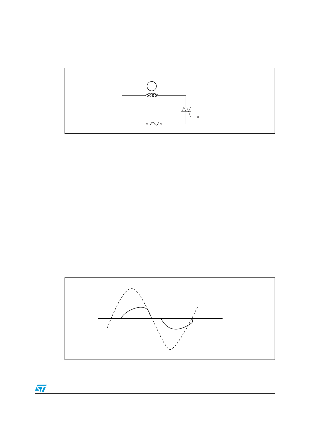
1.2 Example 2: motor control (1)
Figure 4. Control of a small motor by TRIAC
M
Induction motor
The designer wishes to control a small high-impedance motor (2500 Ω, for example) by a
TRIAC. He obtains the parts and an operating manual and carries out some tests. The
circuit, based on that in Figure 4, operates as expected at first. However, after one year of
production, the manufacturer complains of low torque in the motor and blames the TRIAC.
What’s happened?
The circuit was designed with a type of TRIAC whose maximum specified holding current I
H
was 50 mA. But the TRIACs used for the tests were not worst-case, they were more
sensitive, having I
= 13 mA and IH- = 8 mA. The designer based his choice on these
H+
results.
After a year of delivery, the component manufacturer continues to deliver parts which are in
conformity with the specification but less sensitive than before, in fact now I
I
= 20 mA, typically.
H-
= 40 mA and
H+
With these different values the conduction time decreases, the asymmetry is greater as
shown in Figure 5, and the resulting DC component of current causes the motor to gradually
lose torque.
To prevent this kind of difficulty, one must, when designing the circuit, take into account not
the typical value of the sample used but the worst-case value specified by the component
manufacturer.
Figure 5. Voltage across the TRIAC and current for the motor control
V
I
I
H +
I
H –
t
3/10
Page 4

Application examples AN302
1.3 Example 3: motor control (2)
This time, the designer selects a TRIAC with a lower maximum specified holding current, IH.
The small high-impedance motor (Figure 4) seems to operate without problems. However,
the motor is intended for mounting on out-door equipment. It is installed in summer and
works well. But in winter, the fault described above occurs.
What has happened?
The designer studied the operation of his circuit at an ambient temperature of 25 °C. But the
holding current varies inversely with the temperature. Thus, as the temperature decreases,
the holding current increases and the phenomenon described in example 2 occurs.
Again, it is essential to take into account the temperature effects on the device parameters
for circuits which have to operate at extremes of temperature. It is not sufficient to use the
values given for an ambient temperature of 25 °C.
4/10
Page 5

AN302 Holding current - the details
2 Holding current - the details
The three examples in the previous chapter illustrate the importance of the holding current
parameter and the different problems it can cause if it is not taken into account at an early
stage in the design cycle.
If the device is to remain in the conducting state, it is imperative that the circuit in which it is
used ensures an operating current sufficiently high.
In our data sheets, for all types of TRIACs, the holding current, I
maximum value. Then, corrections must be made to compensate for temperature variations.
2.1 Measuring the holding current
In Figure 6 push button R is used to fire the TRIAC. The value of the conducting current IT is
set to be much higher than the latching current I
current I
TRIAC is blocked.
The holding current is always measured with the gate unconnected, that is disconnected
from the trigger circuit and without bias. However, sensitive SCRs, that is, those with a gate
trigger current I
gate and cathode.
For repeatable results, the TRIAC should be suitably turned on. The following guidelines
must be applied.
● The initial value of current I
● If the holding current is measured by pulses (by an automatic tester, for example), the
Figure 6. Circuit for measurement of the holding current I
to decrease. The value of the holding current IH is the value of IT just before the
T
of 200 µA or less, are measured with a 1 kΩ resistor connected between
GT
must be more than five times the latching current IL before
T
the test can begin.
TRIAC should be conducting for at least 500 µs before starting the test.
, is specified as a
H
. Increasing the resistance R causes the
L
H
RR ≥ 33 ohms
V = ± 12V
±I
A
T
A2
A1
G
R
Example:
BTA/BTB12-600C: IL (QI - QIII and QIV) = 40 mA,
so choose I
For a TRIAC, I
A1, and I
H-
documentation only one maximum value is given for both quadrants. This value is always
the higher value.
= 500 mA, IH maximum = 25 mA
T
has two values; IH+, when electrode A2 is positive with respect to electrode
H
, when electrode A2 is negative with respect to electrode A1. In the
5/10
Page 6

Holding current - the details AN302
Depending on the production batch, the holding current can vary. However, the dispersion
always remains below the limits specified in the data sheet. For a better perspective, here
are some figures:
● sensitive TRIAC: I
● standard TRIAC: I
(QI): 5 mA (type TW), 2 mA < IH < 8 mA (specified IH max: 10 mA)
GT
(QI): 50 mA (type B), 8 mA < IH < 40 mA (specified IH max: 50
GT
mA)
The minimum value of the I
parameter is not specified in the data sheets.
H
2.2 Variation of the holding current
2.2.1 Typical variation of IH with device sensitivity and direction of commutation
The holding current, IH, is related to the gate firing current, IGT as shown in Ta b l e 1.
Table 1. Ratio between I
Tria c IH+ / IGT (QI)
Sensitive TRIAC 12 Arms (TW type) 2.5 (approx.)
Standard TRIAC 12 Arms (C type) 1.4 (approx.)
Example:
BTA/BTB12-600TW: if IGT (QI) = 1.5 mA then IH+ = 3.8 mA.
BTA/BTB12-600C: if I
In the case of the TRIAC (as opposed to the thyristor), it is important to note that current I
(electrode A2 negative with respect to A1) can be higher or lower than I
rated current and the device technology.
and IGT (QI) for sensitive and standard TRIACs
H+
(QI) = 10 mA then IH+ = 14 mA.
GT
according to the
H+
H-
Table 2. Ratio between IH+ and IH- for sensitive and standard TRIACs
Tria c IH+ / I
Sensitive TRIAC 12 Arms (TW type) 0.9 (approx.)
Standard TRIAC 12 Arms (C type) 1.8 (approx.)
Example:
BTA/BTB06-600TW: if IH+ = 4.3 mA, I
BTA/BTB12-600C: if I
= 15 mA, I
H+
= 4.8 mA.
H-
= 8.3 mA.
H-
2.2.2 Variation of IH with junction temperature
The holding current is physically related to the firing current, IGT. These two parameters vary
with the junction temperature as shown in Figure 7.
Example:
Triac TO-220AB, type BTA/BTB12-600C: IH = 20 mA at Tj = 25 °C and 14 mA at 110 °C.
6/10
H-
Page 7

AN302 Holding current - the details
Figure 7. Relative variation of IH, with the junction temperature, Tj
2.2.3 Effect of reapplied voltage
The rise time and the level of the reapplied reverse voltage across the TRIAC after blocking
have no effect on the value of its holding current, I
.
H
2.2.4 Influence of the external gate cathode resistor
Figure 8. Variation of IH, of a sensitive thyristor with RGK
Note: The hypostatic current for sensitive thyristors is always specified for RGK= 1000ohms.
Some applications require a resistor, R
, to be connected between the gate and the
GK
cathode of the component, either to improve its behavior under voltage at high junction
temperatures (by-pass for leakage current) in the case of sensitive thyristors or because it
forms part of the firing circuit. The value of this resistor, as well as the sensitivity of the
component, affects the holding current as shown in Figure 8.
Sensitive thyristors (IGT < 200 µA)
For sensitive thyristors RGK has a large influence on the holding current as shown by
Figure 9. Thus, in certain applications, the designer may want to use a high-impedance
control circuit.
Standard thyristors, sensitive and standard TRIACs
Here, RGK has no significant effect on the holding current provided that it is not too low, that
is, R
should be greater than 20 Ω.
GK
7/10
Page 8

Holding current - the details AN302
Figure 9. A Darlington TRIAC for high sensitivity with high holding current
T1: standard triac
e.g. BTA/BTB12 -600B: I
T2: sensitive triac
e.g. BTA/BTB12 -600TW: I
GT
I
H
I
= 50mA
= 50mA
= 5mA
GT
= 10mA
H
2.3 Combining characteristics
We have seen that the more sensitive the TRIAC (lower IG), the lower the value of the
holding current, I
Now, in certain applications a sensitive TRIAC with a high holding current, I
required. In this case, two TRIACs, a sensitive one and a standard one, connected as a
“Darlington” pair could be used as shown in Figure 9. The assembly is sensitive but has a
higher holding current.
.
H
(or IL), may be
H
8/10
Page 9

AN302 Conclusions
3 Conclusions
The choice of a thyristor or a TRIAC does not depend only on the voltage, the rated current
and the sensitivity. Other parameters must be taken into account to ensure reliability.
The holding or hypostatic current, I
this parameter varies with:
● dispersion of the characteristics at manufacture
● temperature
● control circuit (in the case of sensitive thyristors)
● direction of current flow.
Taking into account these elements, the designer can obtain satisfactory operation of his
circuit in industrial real-life applications.
4 Revision history
Table 3. Document revision history
Date Revision Changes
Feb-1989 1 First issue
30-Mar-2004 2 Stylesheet update. No content change.
10-Mar-2008 3 Reformatted to current standards. Complete technical review
, plays an important role in many circuits. The value of
H
9/10
Page 10

AN302
Please Read Carefully:
Information in this document is provided solely in connection with ST products. STMicroelectronics NV and its subsidiaries (“ST”) reserve the
right to make changes, corrections, modifications or improvements, to this document, and the products and services described herein at any
time, without notice.
All ST products are sold pursuant to ST’s terms and conditions of sale.
Purchasers are solely responsible for the choice, selection and use of the ST products and services described herein, and ST assumes no
liability whatsoever relating to the choice, selection or use of the ST products and services described herein.
No license, express or implied, by estoppel or otherwise, to any intellectual property rights is granted under this document. If any part of this
document refers to any third party products or services it shall not be deemed a license grant by ST for the use of such third party products
or services, or any intellectual property contained therein or considered as a warranty covering the use in any manner whatsoever of such
third party products or services or any intellectual property contained therein.
UNLESS OTHERWISE SET FORTH IN ST’S TERMS AND CONDITIONS OF SALE ST DISCLAIMS ANY EXPRESS OR IMPLIED
WARRANTY WITH RESPECT TO THE USE AND/OR SALE OF ST PRODUCTS INCLUDING WITHOUT LIMITATION IMPLIED
WARRANTIES OF MERCHANTABILITY, FITNESS FOR A PARTICULAR PURPOSE (AND THEIR EQUIVALENTS UNDER THE LAWS
OF ANY JURISDICTION), OR INFRINGEMENT OF ANY PATENT, COPYRIGHT OR OTHER INTELLECTUAL PROPERTY RIGHT.
UNLESS EXPRESSLY APPROVED IN WRITING BY AN AUTHORIZED ST REPRESENTATIVE, ST PRODUCTS ARE NOT
RECOMMENDED, AUTHORIZED OR WARRANTED FOR USE IN MILITARY, AIR CRAFT, SPACE, LIFE SAVING, OR LIFE SUSTAINING
APPLICATIONS, NOR IN PRODUCTS OR SYSTEMS WHERE FAILURE OR MALFUNCTION MAY RESULT IN PERSONAL INJURY,
DEATH, OR SEVERE PROPERTY OR ENVIRONMENTAL DAMAGE. ST PRODUCTS WHICH ARE NOT SPECIFIED AS "AUTOMOTIVE
GRADE" MAY ONLY BE USED IN AUTOMOTIVE APPLICATIONS AT USER’S OWN RISK.
Resale of ST products with provisions different from the statements and/or technical features set forth in this document shall immediately void
any warranty granted by ST for the ST product or service described herein and shall not create or extend in any manner whatsoever, any
liability of ST.
ST and the ST logo are trademarks or registered trademarks of ST in various countries.
Information in this document supersedes and replaces all information previously supplied.
The ST logo is a registered trademark of STMicroelectronics. All other names are the property of their respective owners.
© 2008 STMicroelectronics - All rights reserved
STMicroelectronics group of companies
Australia - Belgium - Brazil - Canada - China - Czech Republic - Finland - France - Germany - Hong Kong - India - Israel - Italy - Japan -
Malaysia - Malta - Morocco - Singapore - Spain - Sweden - Switzerland - United Kingdom - United States of America
www.st.com
10/10
 Loading...