ST AN3011 Application note

AN3011

Application note

Wide range input (90 - 265), single output (5 V-11 W) EVLVIP27H-12SB, VIPer27 demonstration board

Introduction

In certain applications such as LCD or plasma TVs, desk top computers, etc., the power supply that converts the energy from the mains often includes two modules: the main power supply that provides most of the power which is off when the application is off or in standby mode, and the auxiliary power supply that only provides energy to specific parts of the equipment, like the USB ports, remote receivers, or modems, but stays on when the application is in standby mode.

In standby mode it is often required that the equipment input power is as low as possible, which means reducing the input power of the auxiliary power supply, in no-load or light-load conditions, as low as possible. This demonstration board meets the specifications of a wide range of auxiliary power supplies for the above mentioned applications. Furthermore, it is optimized for very low standby consumption which helps to meet the most stringent energy saving requirements. Using the VIPer27, which has a switching frequency of 115 kHz, helps to reduce the transformer size.

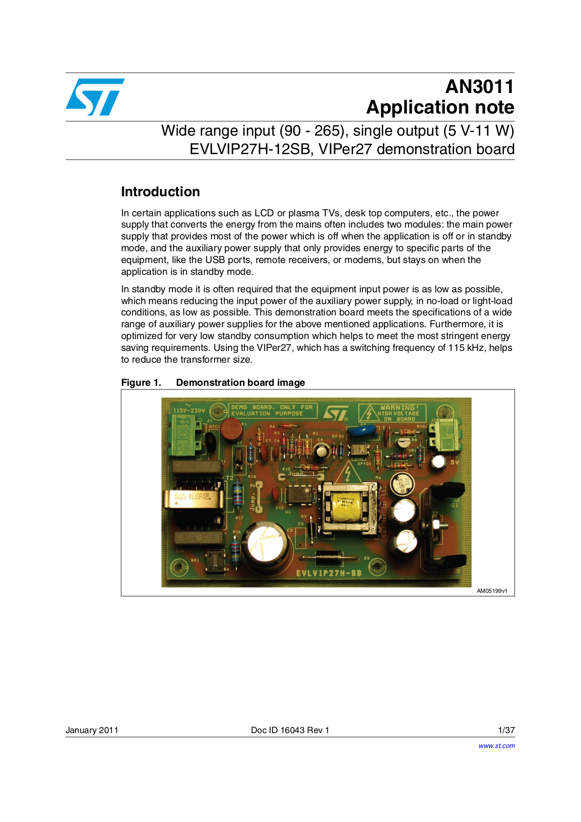
Figure 1. Demonstration board image

!-V

January 2011

Doc ID 16043 Rev 1

1/37

www.st.com

Contents

AN3011


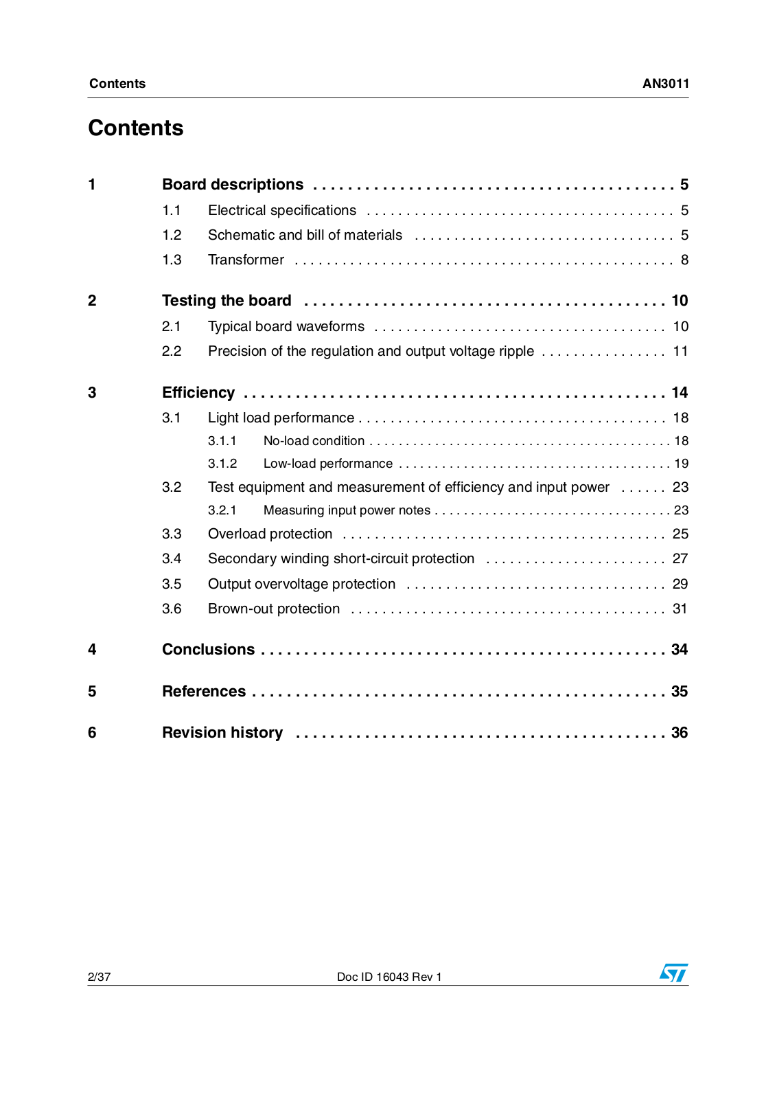
Contents

1

Board descriptions . . . . . . . . . . . . . . . . . . . . . . . . . . . . . . . . . . . . . . . . . .

5


1.1

Electrical specifications . . . . . . . . . . . . . . . . . . . . . . . . . . . . . . . . . . . . . . .

5


1.2

Schematic and bill of materials . . . . . . . . . . . . . . . . . . . . . . . . . . . . . . . . .

5


1.3

Transformer . . . . . . . . . . . . . . . . . . . . . . . . . . . . . . . . . . . . . . . . . . . . . . . .

8

2

Testing the board . . . . . . . . . . . . . . . . . . . . . . . . . . . . . . . . . . . . . . . . . .

10


2.1

Typical board waveforms . . . . . . . . . . . . . . . . . . . . . . . . . . . . . . . . . . . . .

10


2.2

Precision of the regulation and output voltage ripple . . . . . . . . . . . . . . . .

11

3

Efficiency . . . . . . . . . . . . . . . . . . . . . . . . . . . . . . . . . . . . . . . . . . . . . . . . .

14


3.1

Light load performance . . . . . . . . . . . . . . . . . . . . . . . . . . . . . . . . . . . . . . .

18

3.1.1 No-load condition . . . . . . . . . . . . . . . . . . . . . . . . . . . . . . . . . . . . . . . . . . 18 3.1.2 Low-load performance . . . . . . . . . . . . . . . . . . . . . . . . . . . . . . . . . . . . . . 19

3.2

Test equipment and measurement of efficiency and input power . . . . . .

23


3.2.1

Measuring input power notes . . . . . . . . . . . . . . . . . . . . . . . . . . . . . . . . .

23

3.3 Overload protection . . . . . . . . . . . . . . . . . . . . . . . . . . . . . . . . . . . . . . . . . 25 3.4 Secondary winding short-circuit protection . . . . . . . . . . . . . . . . . . . . . . . 27 3.5 Output overvoltage protection . . . . . . . . . . . . . . . . . . . . . . . . . . . . . . . . . 29 3.6 Brown-out protection . . . . . . . . . . . . . . . . . . . . . . . . . . . . . . . . . . . . . . . . 31

4

Conclusions . . . . . . . . . . . . . . . . . . . . . . . . . . . . . . . . . . . . . . . . . . . . . . .

34

5

References . . . . . . . . . . . . . . . . . . . . . . . . . . . . . . . . . . . . . . . . . . . . . . . .

35

6

Revision history . . . . . . . . . . . . . . . . . . . . . . . . . . . . . . . . . . . . . . . . . . .

36

2/37

Doc ID 16043 Rev 1

AN3011

List of tables


List of tables

Table 1. Electrical specifications. . . . . . . . . . . . . . . . . . . . . . . . . . . . . . . . . . . . . . . . . . . . . . . . . . . . . 5 Table 2. BOM . . . . . . . . . . . . . . . . . . . . . . . . . . . . . . . . . . . . . . . . . . . . . . . . . . . . . . . . . . . . . . . . . . . 7 Table 3. Transformer characteristics . . . . . . . . . . . . . . . . . . . . . . . . . . . . . . . . . . . . . . . . . . . . . . . . . 8

Table 4. Output voltage and VDD line-load regulation. . . . . . . . . . . . . . . . . . . . . . . . . . . . . . . . . . . . 11 Table 5. Efficiency . . . . . . . . . . . . . . . . . . . . . . . . . . . . . . . . . . . . . . . . . . . . . . . . . . . . . . . . . . . . . . 14

Table 6. Active-mode efficiency . . . . . . . . . . . . . . . . . . . . . . . . . . . . . . . . . . . . . . . . . . . . . . . . . . . . 15 Table 7. Line voltage average efficiency vs load . . . . . . . . . . . . . . . . . . . . . . . . . . . . . . . . . . . . . . . 16 Table 8. Energy efficiency criteria for standard models . . . . . . . . . . . . . . . . . . . . . . . . . . . . . . . . . . 17 Table 9. Energy efficiency criteria for low voltage models . . . . . . . . . . . . . . . . . . . . . . . . . . . . . . . . 17 Table 10. No-load input power . . . . . . . . . . . . . . . . . . . . . . . . . . . . . . . . . . . . . . . . . . . . . . . . . . . . . . 18 Table 11. Energy consumption criteria for no-load . . . . . . . . . . . . . . . . . . . . . . . . . . . . . . . . . . . . . . . 18

Table 12. Low-load performance. POUT = 30 mW (brown-out disabled) . . . . . . . . . . . . . . . . . . . . . . 19 Table 13. Low-load performance. POUT = 30 mW (brown-out enabled) . . . . . . . . . . . . . . . . . . . . . . . 19 Table 14. Low-load performance. POUT = 50 mW (brown-out disabled) . . . . . . . . . . . . . . . . . . . . . . 19 Table 15. Low-load performance. POUT = 50 mW (brown-out enabled) . . . . . . . . . . . . . . . . . . . . . . . 20 Table 16. Low-load performance. POUT = 100 mW (brown-out disabled) . . . . . . . . . . . . . . . . . . . . . 20 Table 17. Low-load performance. POUT = 100 mW (brown-out enabled) . . . . . . . . . . . . . . . . . . . . . . 20 Table 18. Low-load performance. POUT = 200 mW (brown-out disabled) . . . . . . . . . . . . . . . . . . . . . 21 Table 19. Output power when the input power is 1 W (BR disabled) . . . . . . . . . . . . . . . . . . . . . . . . . 22

Table 20. Output power when the input power is 1 W (BR enabled) . . . . . . . . . . . . . . . . . . . . . . . . . 22 Table 21. Overvoltage protection activation level test results. . . . . . . . . . . . . . . . . . . . . . . . . . . . . . . 30 Table 22. Document revision history . . . . . . . . . . . . . . . . . . . . . . . . . . . . . . . . . . . . . . . . . . . . . . . . . 36

Doc ID 16043 Rev 1

3/37

List of figures

AN3011


List of figures

Figure 1. Demonstration board image . . . . . . . . . . . . . . . . . . . . . . . . . . . . . . . . . . . . . . . . . . . . . . . . . 1 Figure 2. Schematic . . . . . . . . . . . . . . . . . . . . . . . . . . . . . . . . . . . . . . . . . . . . . . . . . . . . . . . . . . . . . . . 6 Figure 3. Transformer size - top view . . . . . . . . . . . . . . . . . . . . . . . . . . . . . . . . . . . . . . . . . . . . . . . . . 9 Figure 4. Transformer size - side view. . . . . . . . . . . . . . . . . . . . . . . . . . . . . . . . . . . . . . . . . . . . . . . . . 9 Figure 5. Pin placement diagram - bottom view. . . . . . . . . . . . . . . . . . . . . . . . . . . . . . . . . . . . . . . . . . 9 Figure 6. Pin placement diagram - electrical diagram . . . . . . . . . . . . . . . . . . . . . . . . . . . . . . . . . . . . . 9

Figure 7. Drain current and voltage at full-load 115 VAC . . . . . . . . . . . . . . . . . . . . . . . . . . . . . . . . . . 10 Figure 8. Drain current and voltage at full-load 230 VAC . . . . . . . . . . . . . . . . . . . . . . . . . . . . . . . . . . 10 Figure 9. Drain current and voltage at full-load 90 VAC . . . . . . . . . . . . . . . . . . . . . . . . . . . . . . . . . . . 10 Figure 10. Drain current and voltage at full-load 265 VAC . . . . . . . . . . . . . . . . . . . . . . . . . . . . . . . . . . 10 Figure 11. Output voltage ripple 115 VINAC full-load . . . . . . . . . . . . . . . . . . . . . . . . . . . . . . . . . . . . . . 12 Figure 12. Output voltage ripple 230 VINAC full-load . . . . . . . . . . . . . . . . . . . . . . . . . . . . . . . . . . . . . . 12 Figure 13. Output voltage ripple 115 VINAC no-load (burst mode) . . . . . . . . . . . . . . . . . . . . . . . . . . . . 13 Figure 14. Output voltage ripple 230 VINAC 50 mA load (burst mode). . . . . . . . . . . . . . . . . . . . . . . . . 13 Figure 15. Efficiency vs VIN . . . . . . . . . . . . . . . . . . . . . . . . . . . . . . . . . . . . . . . . . . . . . . . . . . . . . . . . . 14 Figure 16. Efficiency vs load . . . . . . . . . . . . . . . . . . . . . . . . . . . . . . . . . . . . . . . . . . . . . . . . . . . . . . . . 15

Figure 17. Active mode efficiency vs VIN . . . . . . . . . . . . . . . . . . . . . . . . . . . . . . . . . . . . . . . . . . . . . . 16 Figure 18. Input voltage average efficiency vs load. . . . . . . . . . . . . . . . . . . . . . . . . . . . . . . . . . . . . . . 16 Figure 19. ENERGY STAR efficiency criteria . . . . . . . . . . . . . . . . . . . . . . . . . . . . . . . . . . . . . . . . . . . 17 Figure 20. Converter input power vs Vin_ac in light-load condition . . . . . . . . . . . . . . . . . . . . . . . . . . . 21 Figure 21. Converter efficiency vs Vin_ac in light-load condition. . . . . . . . . . . . . . . . . . . . . . . . . . . . . 22 Figure 22. Efficiency vs AC input voltage when the input power is 1 W . . . . . . . . . . . . . . . . . . . . . . . 23 Figure 23. Wattmeter possible connections with the U.U.T. (unit under test) . . . . . . . . . . . . . . . . . . . 24 Figure 24. Wattmeter connection scheme for low input current. . . . . . . . . . . . . . . . . . . . . . . . . . . . . . 24 Figure 25. Wattmeter connection scheme for high input current . . . . . . . . . . . . . . . . . . . . . . . . . . . . . 25 Figure 26. Output short-circuit . . . . . . . . . . . . . . . . . . . . . . . . . . . . . . . . . . . . . . . . . . . . . . . . . . . . . . . 26 Figure 27. Operation with output shorted. . . . . . . . . . . . . . . . . . . . . . . . . . . . . . . . . . . . . . . . . . . . . . . 26 Figure 28. Converter power capability . . . . . . . . . . . . . . . . . . . . . . . . . . . . . . . . . . . . . . . . . . . . . . . . . 27 Figure 29. Second overcurrent protection - protection tripping . . . . . . . . . . . . . . . . . . . . . . . . . . . . . . 28 Figure 30. Operating with the secondary winding shorted. Restart mode . . . . . . . . . . . . . . . . . . . . . . 28 Figure 31. OVP circuit . . . . . . . . . . . . . . . . . . . . . . . . . . . . . . . . . . . . . . . . . . . . . . . . . . . . . . . . . . . . . 29 Figure 32. OVP protection . . . . . . . . . . . . . . . . . . . . . . . . . . . . . . . . . . . . . . . . . . . . . . . . . . . . . . . . . . 30 Figure 33. OVP protection . . . . . . . . . . . . . . . . . . . . . . . . . . . . . . . . . . . . . . . . . . . . . . . . . . . . . . . . . . 30 Figure 34. J7 jumper setting. Brown-out disabled . . . . . . . . . . . . . . . . . . . . . . . . . . . . . . . . . . . . . . . . 32 Figure 35. J7 jumper setting. Brown-out enabled . . . . . . . . . . . . . . . . . . . . . . . . . . . . . . . . . . . . . . . . 32 Figure 36. Brown-out protection, internal block diagram . . . . . . . . . . . . . . . . . . . . . . . . . . . . . . . . . . . 32

Figure 37. Input AC voltage steps from 90 VAC to 65 VAC. . . . . . . . . . . . . . . . . . . . . . . . . . . . . . . . . . 33 Figure 38. Input voltage steps from 90 VAC to 0 VAC. . . . . . . . . . . . . . . . . . . . . . . . . . . . . . . . . . . . . . 33

4/37

Doc ID 16043 Rev 1

AN3011

Board descriptions


1 Board descriptions

1.1Electrical specifications

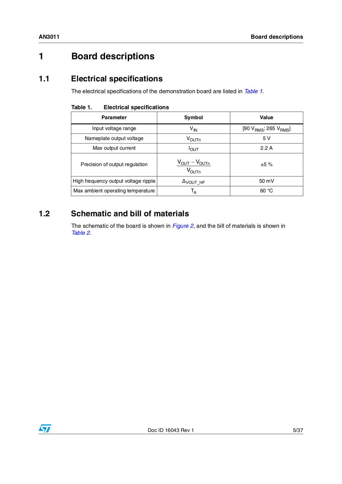
The electrical specifications of the demonstration board are listed in Table 1.

Table 1.

Electrical specifications


Parameter


Symbol

Value


Input voltage range


VIN

[90 VRMS; 265 VRMS]

Nameplate output voltage


VOUTn

5 V


Max output current


IOUT

2.2 A

Precision of output regulation


VOUT − VOUTn


±5 %


VOUTn


High frequency output voltage ripple


VOUT_HF

50 mV


Max ambient operating temperature


TA

60 °C

1.2Schematic and bill of materials

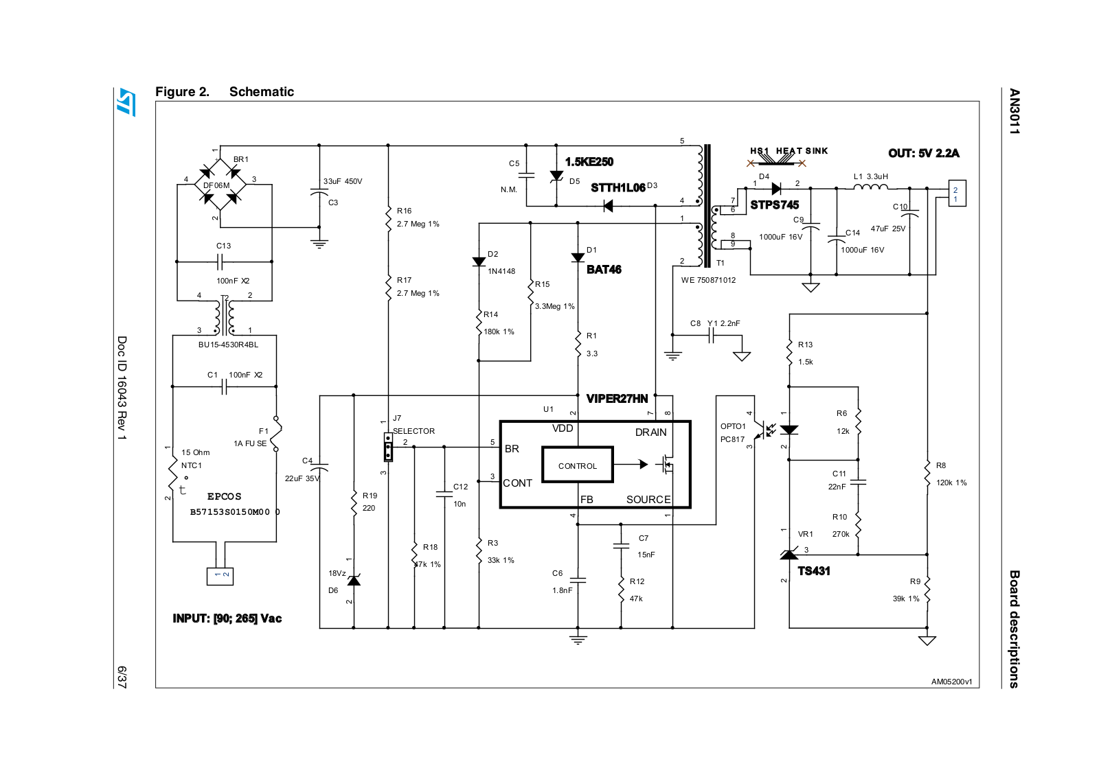
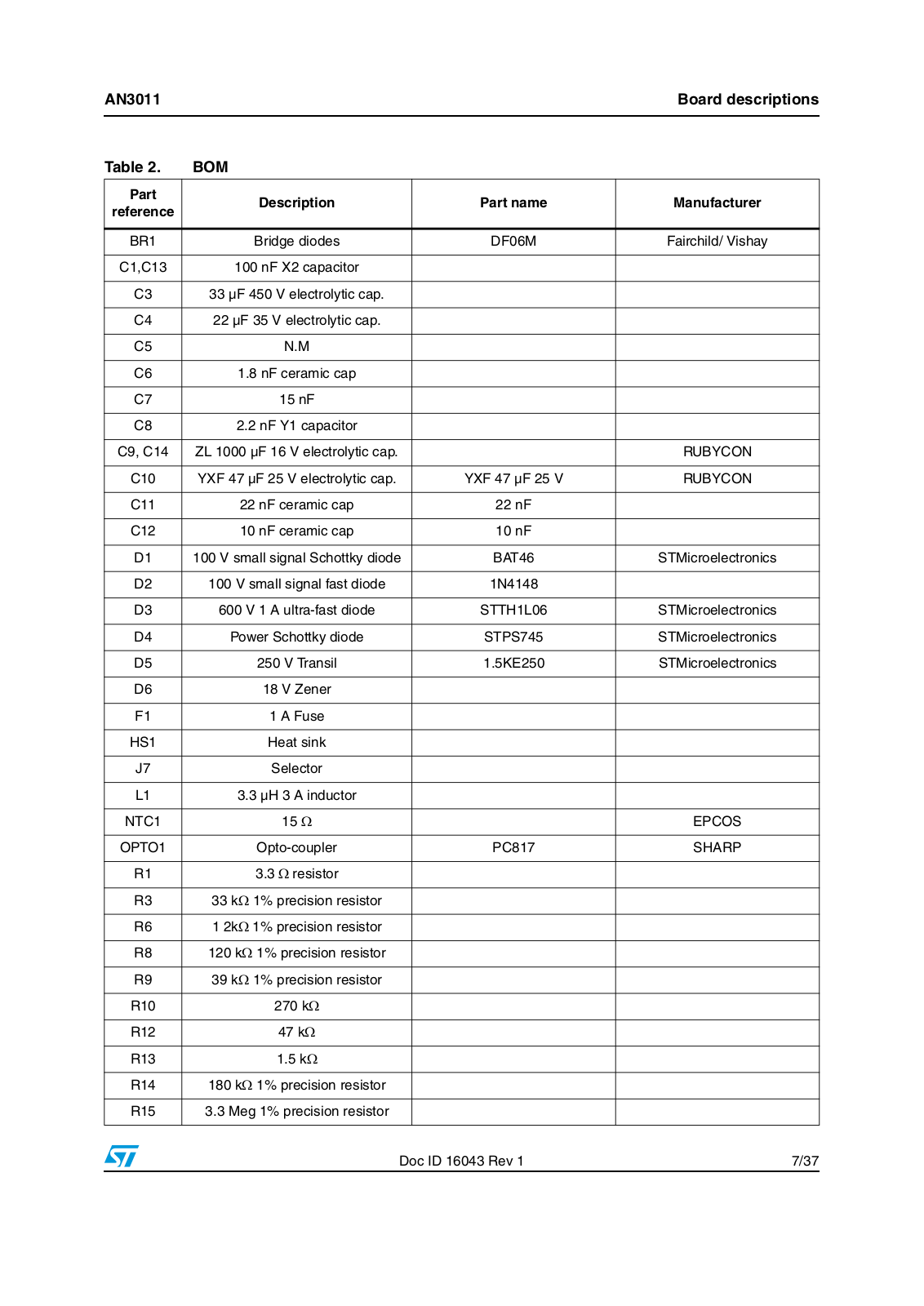
The schematic of the board is shown in Figure 2, and the bill of materials is shown in

Table 2.

Doc ID 16043 Rev 1

5/37

ST AN3011 Application note

Figure 2.


Schematic


AN3011


+6

+( $ 7 6 ,1 .


287 9$


%5


&


.(


X) 9


'


'


/ X+


677+ /'


') 0


1 0


&


6736


5


&


0HJ


&


X) 9


&


X) 9


&


'


'


X) 9


7


1


%$7


Q);


5


:(


5


0HJ


7


0HJ


5


&

< Q)


N


Doc


5


%8 5 %/


5


N


ID


&

Q) ;


16043


8


9,3(5 +1


Rev


-


2372


5


)


N


1


6(/(&725


9''


'5$,1

3&


$)8 6(


2KP


&


%5


17&


&21752/


5


&


X) 9


W

(3&26

5

&

&217


Q)


N


Q


)%

6285&(


% 6 0


5


&


95

N


5


5


Q)


N

N


76


9]


&


Board


5


5


'


Q)


N


N


,1387 > @ 9DF


descriptions

6/37


!-V


AN3011


Board descriptions


Table 2.

BOM


Part

Description

Part name

Manufacturer

reference


BR1

Bridge diodes

DF06M

Fairchild/ Vishay


C1,C13

100 nF X2 capacitor


C3

33 µF 450 V electrolytic cap.


C4

22 µF 35 V electrolytic cap.


C5

N.M


C6

1.8 nF ceramic cap


C7

15 nF


C8

2.2 nF Y1 capacitor


C9, C14

ZL 1000 µF 16 V electrolytic cap.


RUBYCON


C10

YXF 47 µF 25 V electrolytic cap.

YXF 47 µF 25 V

RUBYCON


C11

22 nF ceramic cap

22 nF


C12

10 nF ceramic cap

10 nF


D1

100 V small signal Schottky diode

BAT46

STMicroelectronics


D2

100 V small signal fast diode

1N4148


D3

600 V 1 A ultra-fast diode

STTH1L06

STMicroelectronics


D4

Power Schottky diode

STPS745

STMicroelectronics


D5

250 V Transil

1.5KE250

STMicroelectronics


D6

18 V Zener


F1

1 A Fuse


HS1

Heat sink


J7

Selector


L1

3.3 µH 3 A inductor


NTC1

15 Ω


EPCOS


OPTO1

Opto-coupler

PC817

SHARP


R1

3.3 Ω resistor


R3

33 kΩ 1% precision resistor


R6

1 2kΩ 1% precision resistor


R8

120 kΩ 1% precision resistor


R9

39 kΩ 1% precision resistor


R10

270 kΩ


R12

47 kΩ


R13

1.5 kΩ


R14

180 kΩ 1% precision resistor


R15

3.3 Meg 1% precision resistor


Doc ID 16043 Rev 1

7/37

Board descriptions


AN3011


Table 2.

BOM (continued)


Part

Description

Part name

Manufacturer

reference


R16, R17

2.7 Meg 1% precision resistor


R18

47 kΩ 1% precision resistor


R19

220 Ω


T1

Switch mode transformer

WE - 750871012

Würth Elektronik


T2

Common mode line filter

BU15-4530R4BL

Coilcraft


U1

Offline switching regulator

VIPER27HN

STMicroelectronics


VR1

Voltage reference

TS431

STMicroelectronics


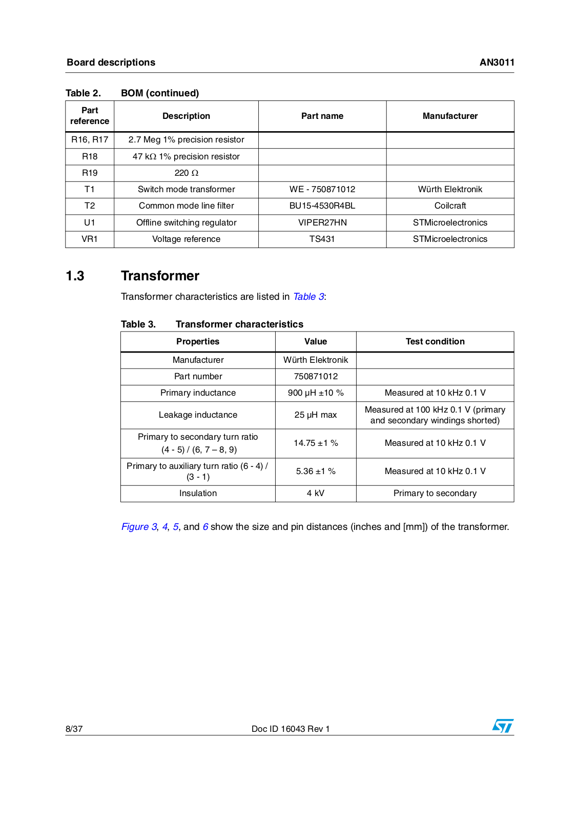
1.3Transformer

Transformer characteristics are listed in Table 3:

Table 3.

Transformer characteristics


Properties

Value

Test condition


Manufacturer

Würth Elektronik


Part number

750871012


Primary inductance

900 µH ±10 %

Measured at 10 kHz 0.1 V


Leakage inductance

25 µH max

Measured at 100 kHz 0.1 V (primary


and secondary windings shorted)


Primary to secondary turn ratio

14.75 ±1 %

Measured at 10 kHz 0.1 V


(4 - 5) / (6, 7 – 8, 9)


Primary to auxiliary turn ratio (6 - 4) /

5.36 ±1 %

Measured at 10 kHz 0.1 V


(3 - 1)


Insulation

4 kV

Primary to secondary


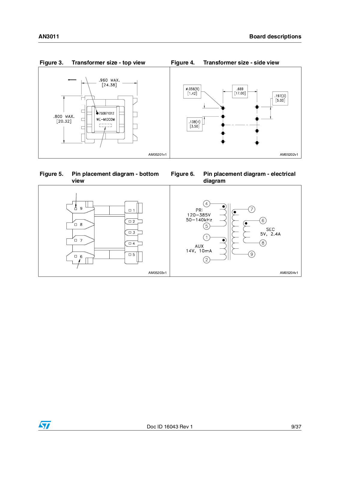
Figure 3, 4, 5, and 6 show the size and pin distances (inches and [mm]) of the transformer.

8/37

Doc ID 16043 Rev 1

AN3011

Board descriptions


Figure 3. Transformer size - top view

Figure 4. Transformer size - side view


!-V

!-V

Figure 5. Pin placement diagram - bottom view

Figure 6. Pin placement diagram - electrical diagram

!-V

!-V


Doc ID 16043 Rev 1

9/37

Testing the board

AN3011


2 Testing the board

2.1Typical board waveforms

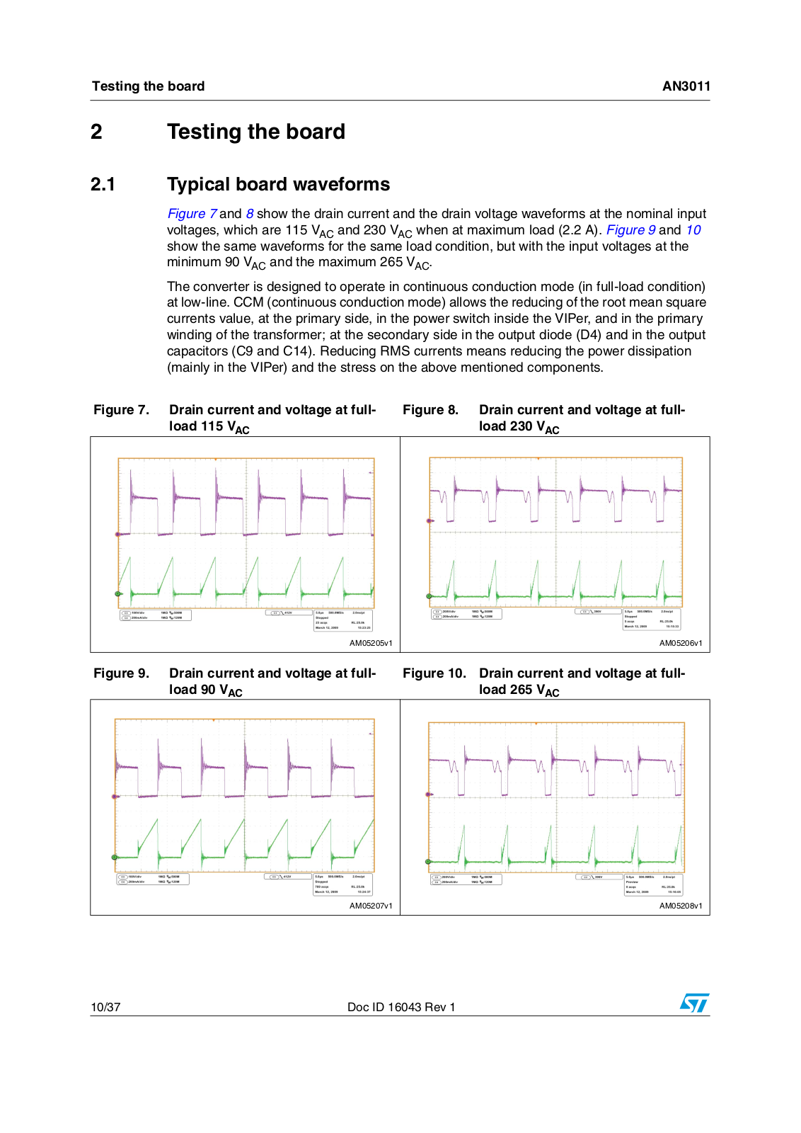
Figure 7 and 8 show the drain current and the drain voltage waveforms at the nominal input voltages, which are 115 VAC and 230 VAC when at maximum load (2.2 A). Figure 9 and 10 show the same waveforms for the same load condition, but with the input voltages at the minimum 90 VAC and the maximum 265 VAC.

The converter is designed to operate in continuous conduction mode (in full-load condition) at low-line. CCM (continuous conduction mode) allows the reducing of the root mean square currents value, at the primary side, in the power switch inside the VIPer, and in the primary winding of the transformer; at the secondary side in the output diode (D4) and in the output capacitors (C9 and C14). Reducing RMS currents means reducing the power dissipation (mainly in the VIPer) and the stress on the above mentioned components.

Figure 7. Drain current and voltage at fullload 115 VAC

Figure 8. Drain current and voltage at fullload 230 VAC

!-V

!-V


Figure 9. Drain current and voltage at fullload 90 VAC

Figure 10. Drain current and voltage at fullload 265 VAC

!-V

!-V


10/37

Doc ID 16043 Rev 1

AN3011

Testing the board


2.2Precision of the regulation and output voltage ripple

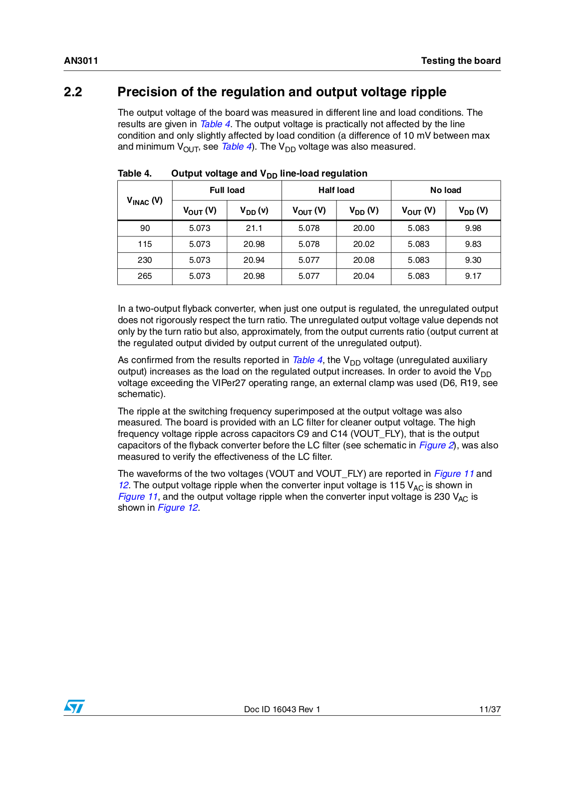
The output voltage of the board was measured in different line and load conditions. The results are given in Table 4. The output voltage is practically not affected by the line condition and only slightly affected by load condition (a difference of 10 mV between max and minimum VOUT, see Table 4). The VDD voltage was also measured.

Table 4.

Output voltage and VDD line-load regulation


VINAC (V)

Full load

Half load

No load


VOUT (V)

VDD (v)

VOUT (V)

VDD (V)

VOUT (V)

VDD (V)


90

5.073

21.1

5.078

20.00

5.083

9.98


115

5.073

20.98

5.078

20.02

5.083

9.83


230

5.073

20.94

5.077

20.08

5.083

9.30


265

5.073

20.98

5.077

20.04

5.083

9.17


In a two-output flyback converter, when just one output is regulated, the unregulated output does not rigorously respect the turn ratio. The unregulated output voltage value depends not only by the turn ratio but also, approximately, from the output currents ratio (output current at the regulated output divided by output current of the unregulated output).

As confirmed from the results reported in Table 4, the VDD voltage (unregulated auxiliary output) increases as the load on the regulated output increases. In order to avoid the VDD voltage exceeding the VIPer27 operating range, an external clamp was used (D6, R19, see schematic).

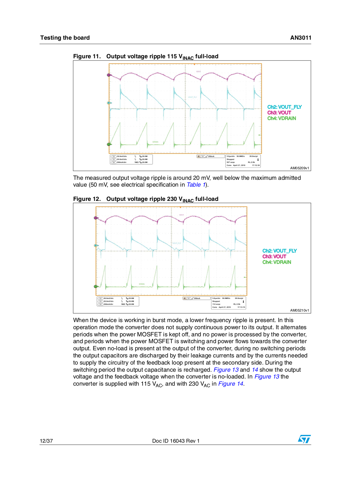
The ripple at the switching frequency superimposed at the output voltage was also measured. The board is provided with an LC filter for cleaner output voltage. The high frequency voltage ripple across capacitors C9 and C14 (VOUT_FLY), that is the output capacitors of the flyback converter before the LC filter (see schematic in Figure 2), was also measured to verify the effectiveness of the LC filter.

The waveforms of the two voltages (VOUT and VOUT_FLY) are reported in Figure 11 and 12. The output voltage ripple when the converter input voltage is 115 VAC is shown in Figure 11, and the output voltage ripple when the converter input voltage is 230 VAC is shown in Figure 12.

Doc ID 16043 Rev 1

11/37

Testing the board

AN3011


Figure 11. Output voltage ripple 115 VINAC full-load

#H 6/54?&,9 #H 6/54 #H 6$2!).

!-V

The measured output voltage ripple is around 20 mV, well below the maximum admitted value (50 mV, see electrical specification in Table 1).

Figure 12. Output voltage ripple 230 VINAC full-load

#H 6/54?&,9 #H 6/54 #H 6$2!).

!-V

When the device is working in burst mode, a lower frequency ripple is present. In this operation mode the converter does not supply continuous power to its output. It alternates periods when the power MOSFET is kept off, and no power is processed by the converter, and periods when the power MOSFET is switching and power flows towards the converter output. Even no-load is present at the output of the converter, during no switching periods the output capacitors are discharged by their leakage currents and by the currents needed to supply the circuitry of the feedback loop present at the secondary side. During the switching period the output capacitance is recharged. Figure 13 and 14 show the output voltage and the feedback voltage when the converter is no-loaded. In Figure 13 the converter is supplied with 115 VAC, and with 230 VAC in Figure 14.

12/37

Doc ID 16043 Rev 1

Loading...
+ 25 hidden pages