

Page 1

AN2967
Application note
Implementing a driven shield
on STM8T and STM8TS capacitive sensors
Introduction
The STM8T and STM8TS capacitive sensors opens up a new dimension to capacitive
sensing by detecting user’s proximity up to 30 cm. This is a key feature for many endapplications such as personal navigation devices (PNDs) or stove tops which are equipped
with backlighting that switches on when a user is detected. Proximity detectors are also
implemented in white goods, automotive devices, palm tops, and on any type of kitchen or
office appliance where the display needs to be turned on to allow some parameters to be
adjusted by the user.
To enhance their application appearance and ease-of-use, designers can choose to add
proximity detection as an extra feature. The alternative is to implement it to save energy,
allowing the product to remain in sleep mode and only wake up when it detects a user in its
proximity.
May 2009 Doc ID 15601 Rev 1 1/9
www.st.com
Page 2
Interference with proximity detection range AN2967
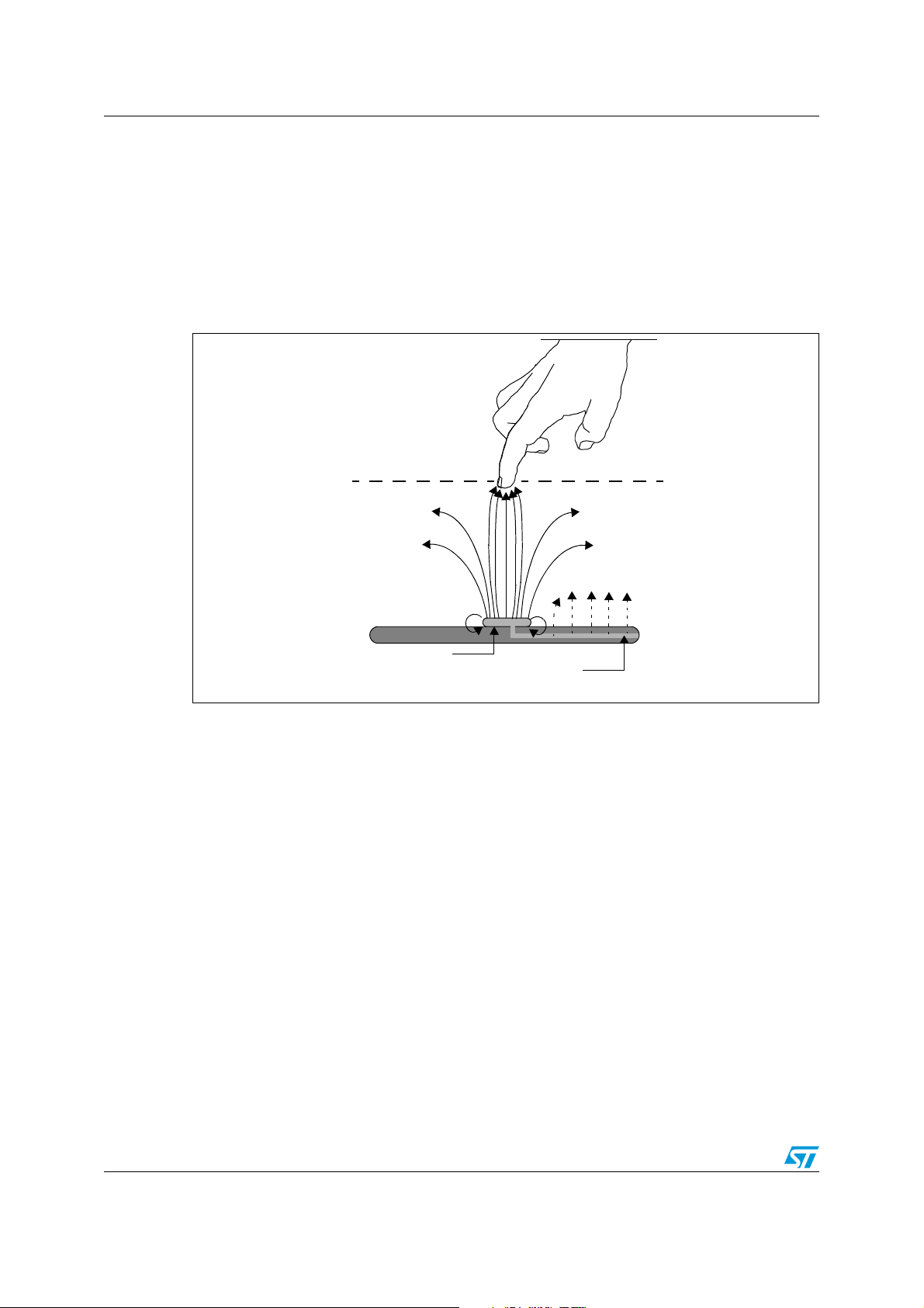
PCB
Trace between sense pad
Sense pad
Detection distance
1 Interference with proximity detection range
Unfortunately in many cases the end-application consists of a metal enclosure or large
grounded metal objects, as can be seen in stove tops or microwave ovens. Metal objects,
ground planes or traces close by a proximity sensing electrode dramatically influence the
sensor detection range. Refer to Figure 1 and Figure 2, for a comparison of the propagation
of the electrical field without and with metal objects in the electrode proximity.
Figure 1. Electrical propagation from a sense pad and its trace
2/9 Doc ID 15601 Rev 1
Page 3
AN2967 Interference with proximity detection range
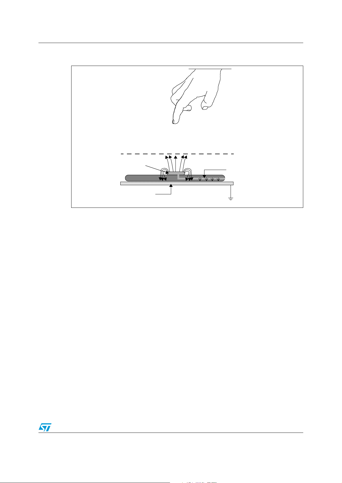
PCB
New detection distance
Ground casing /
metal object
Sense pad
Trace between IC
and sense pad
Figure 2. Electrical propagation from a sense pad and its trace in the presence of a
ground casing / metal object
The propagation from a certain area of a sense pad is directly equivalent to the surface area
of that part of the sense pad. For example, the longer the trace (more extended area)
between the IC and the sense pad, the more the propagation from that trace will be. A
similar phenomenon occurs for the sense antenna.
Figure 1 illustrates the propagation from a trace and sense pad. Adding a ground plane
around the sense antenna causes the electrical propagation to mainly go towards this plane,
as shown in Figure 2. The reduction of sensitivity shown in Figure 2 can also be caused by
components, metal objects or other traces that could results in stray capacitances.
Doc ID 15601 Rev 1 3/9
Page 4

Possible shield solutions AN2967
PCB
Detection distance
Ground casing /
metal object
Trace between IC
and sense pad
Sense pad
Shield implemented as
pour on bottom of PCB
2 Possible shield solutions
The driven shield available on selected STM8T/STM8TS capacitive sensors can be used to
decrease the negative influence a ground plane or metal object on the proximity detection
range. The shield should always be at the same potential as the sense antenna.
For this reason some STM8T/STM8TS devices feature a SHLDIN pin to which a CX channel
can be connected (see Figure 5). The SHDLOUT pin then has the same potential as the CX
channel.
The shield can be implemented in two different ways:
● The shield can protect a whole system as shown in Figure 3.
● The shield can protect only the trace. In this case the sense antenna is isolated from
any interference source (i.e. ground plane, metal object, other traces, user influence on
that trace) as shown in Figure 4.
Figure 3. Shield implemented as pour between sense pad and ground casing /
metal object
4/9 Doc ID 15601 Rev 1
Page 5

AN2967 Possible shield solutions
Detection distance
Ground casing /
metal object
Trace inside shield
Shield
(implemented as coaxial cable)
Sense pad
Figure 4. Shield implemented as coaxial cable shielding trace between sense pad
and IC from ground casing / metal object
Doc ID 15601 Rev 1 5/9
Page 6

Advantages of the shield function AN2967
3 Advantages of the shield function
Some STM8T and STM8TS capacitive sensors have a built-in shielding function. The
advantages of the shield include:
● The sensing antenna (pad) is separated from the sealed electronics.
● The designer can shield the sensing wire from unwanted influences such as ground
planes, metal objects and other traces on the PCB. The shield also counters
environmental interference such as water flowing into a water pipe or people passing
past the sensing wire.
● The shield enhances proximity detection when it is used with battery (DC) applications.
● An integrated driven shield allows to achieve high performance at virtually no additional
cost.
6/9 Doc ID 15601 Rev 1
Page 7

AN2967 Connecting the shield
VDD
SHLDOUT
CX
Plastic jacket
Metal shield
Center core
Dielectric insulator
ai15527
2 kΩ
100 kΩ
R
SHIELD
R
X
SHLDIN
Coaxial cable
4 Connecting the shield
Ideally, a coaxial cable should be used for the shield. A RX (typically 2 kΩ) resistor should be
connected to the CX pin corresponding to the sensing electrode to be shielded. The other
side of the R
connected to the SHLDIN pin. The device has an internal buffer so that the shield does not
add any load impedance to the CX pin.
Note: The SHLDOUT pin should be connected to the metallic shield part of the coaxial cable. A
pull-up resistor (R
(100 kΩ≤R
current consumption.
Refer to Figure 5 for a description of shield implementation using a coaxial cable.
Note: 1 Some products do not feature a SHDLIN pin. This connection is made inside the IC. It still
requires an external R
2 For some devices, it is recommended to use a dedicated CX which sensitivity level can be
set independently from the others. This channel can then be used as proximity sensing
antenna, with advanced sensitivity and minimal parasitic influences.
Figure 5. Connecting the shield (coaxial cable implementation)
resistor is connected to the center core of the coaxial cable. This node is also
X
) should be added between SHLDOUT and VDD
SHIELD
SHIELD
≤ 1MΩ). A smaller R
to be connected between SHLDOUT and VDD.
SHIELD
ensures better shielding but increases
SHIELD
Doc ID 15601 Rev 1 7/9
Page 8

Revision history AN2967
5 Revision history
Table 1. Document revision history
Date Revision Changes
04-May-2009 1 Initial release.
8/9 Doc ID 15601 Rev 1
Page 9

AN2967
Please Read Carefully:
Information in this document is provided solely in connection with ST products. STMicroelectronics NV and its subsidiaries (“ST”) reserve the
right to make changes, corrections, modifications or improvements, to this document, and the products and services described herein at any
time, without notice.
All ST products are sold pursuant to ST’s terms and conditions of sale.
Purchasers are solely responsible for the choice, selection and use of the ST products and services described herein, and ST assumes no
liability whatsoever relating to the choice, selection or use of the ST products and services described herein.
No license, express or implied, by estoppel or otherwise, to any intellectual property rights is granted under this document. If any part of this
document refers to any third party products or services it shall not be deemed a license grant by ST for the use of such third party products
or services, or any intellectual property contained therein or considered as a warranty covering the use in any manner whatsoever of such
third party products or services or any intellectual property contained therein.
UNLESS OTHERWISE SET FORTH IN ST’S TERMS AND CONDITIONS OF SALE ST DISCLAIMS ANY EXPRESS OR IMPLIED
WARRANTY WITH RESPECT TO THE USE AND/OR SALE OF ST PRODUCTS INCLUDING WITHOUT LIMITATION IMPLIED
WARRANTIES OF MERCHANTABILITY, FITNESS FOR A PARTICULAR PURPOSE (AND THEIR EQUIVALENTS UNDER THE LAWS
OF ANY JURISDICTION), OR INFRINGEMENT OF ANY PATENT, COPYRIGHT OR OTHER INTELLECTUAL PROPERTY RIGHT.
UNLESS EXPRESSLY APPROVED IN WRITING BY AN AUTHORIZED ST REPRESENTATIVE, ST PRODUCTS ARE NOT
RECOMMENDED, AUTHORIZED OR WARRANTED FOR USE IN MILITARY, AIR CRAFT, SPACE, LIFE SAVING, OR LIFE SUSTAINING
APPLICATIONS, NOR IN PRODUCTS OR SYSTEMS WHERE FAILURE OR MALFUNCTION MAY RESULT IN PERSONAL INJURY,
DEATH, OR SEVERE PROPERTY OR ENVIRONMENTAL DAMAGE. ST PRODUCTS WHICH ARE NOT SPECIFIED AS "AUTOMOTIVE
GRADE" MAY ONLY BE USED IN AUTOMOTIVE APPLICATIONS AT USER’S OWN RISK.
Resale of ST products with provisions different from the statements and/or technical features set forth in this document shall immediately void
any warranty granted by ST for the ST product or service described herein and shall not create or extend in any manner whatsoever, any
liability of ST.
ST and the ST logo are trademarks or registered trademarks of ST in various countries.
Information in this document supersedes and replaces all information previously supplied.
The ST logo is a registered trademark of STMicroelectronics. All other names are the property of their respective owners.
© 2009 STMicroelectronics - All rights reserved
STMicroelectronics group of companies
Australia - Belgium - Brazil - Canada - China - Czech Republic - Finland - France - Germany - Hong Kong - India - Israel - Italy - Japan -
Malaysia - Malta - Morocco - Philippines - Singapore - Spain - Sweden - Switzerland - United Kingdom - United States of America
www.st.com
Doc ID 15601 Rev 1 9/9
 Loading...