ST AN2946 Application note

AN2946

Application note

Solar-LED streetlight controller with 25 W LED lamp driver and 85 W battery charger based on the STM32F101Rx

Introduction

The solar-LED streetlight controller described in this application note is designed to achieve an 85 W solar energy battery charger and a 25 W LED lamp driver. During the daytime the controller preserves the electricity energy gathered by the solar module (PV module), then stores it in the battery. In the evening the controller uses the battery energy to power the LED streetlight. When the battery runs out of power after several rainy days, the controller enables the external offline power supply (not included in this system) instead of the battery to power the LED streetlight until the system battery is fully charged again.

Due to the clean nature of solar energy, and the highly efficient energy conversion of the PV module and very long operating life of the LED lamp, the solar-LED streetlight controller, compared to conventional streetlights, can save electricity remarkably, thus abating greenhouse gas (e.g. CO2) emission.

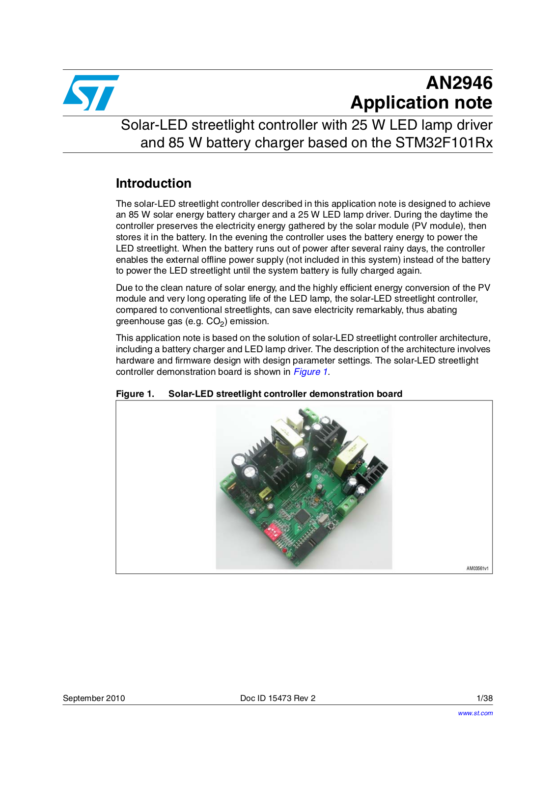
This application note is based on the solution of solar-LED streetlight controller architecture, including a battery charger and LED lamp driver. The description of the architecture involves hardware and firmware design with design parameter settings. The solar-LED streetlight controller demonstration board is shown in Figure 1.

Figure 1. Solar-LED streetlight controller demonstration board

September 2010

Doc ID 15473 Rev 2

1/38

www.st.com

Contents

AN2946


Contents

1

Safety instructions . . . . . . . . . . . . . . . . . . . . . . . . . . . . . . . . . . . . . . . . . .

5


1.1

Intended use . . . . . . . . . . . . . . . . . . . . . . . . . . . . . . . . . . . . . . . . . . . . . . .

5


1.2

Installation . . . . . . . . . . . . . . . . . . . . . . . . . . . . . . . . . . . . . . . . . . . . . . . . .

5


1.3

Electrical connection . . . . . . . . . . . . . . . . . . . . . . . . . . . . . . . . . . . . . . . . .

5


1.4

Board operation . . . . . . . . . . . . . . . . . . . . . . . . . . . . . . . . . . . . . . . . . . . . .

5

2

General description . . . . . . . . . . . . . . . . . . . . . . . . . . . . . . . . . . . . . . . . . .

6


2.1

Controller features . . . . . . . . . . . . . . . . . . . . . . . . . . . . . . . . . . . . . . . . . . .

6


2.2

Solar-LED streetlight system architecture . . . . . . . . . . . . . . . . . . . . . . . . .

6


2.3

Scope of the solar-LED streetlight controller . . . . . . . . . . . . . . . . . . . . . . .

7


2.4

Main functions of the controller . . . . . . . . . . . . . . . . . . . . . . . . . . . . . . . . .

8


2.4.1

Battery charging management . . . . . . . . . . . . . . . . . . . . . . . . . . . . . . . . .

8


2.4.2

LED lamp driving management . . . . . . . . . . . . . . . . . . . . . . . . . . . . . . . .

9


2.4.3

System monitoring circuit . . . . . . . . . . . . . . . . . . . . . . . . . . . . . . . . . . . . .

9

3

Hardware design . . . . . . . . . . . . . . . . . . . . . . . . . . . . . . . . . . . . . . . . . . .

10


3.1 Circuit description . . . . . . . . . . . . . . . . . . . . . . . . . . . . . . . . . . . . . . . . . . .

10

3.1.1 Power supply circuit . . . . . . . . . . . . . . . . . . . . . . . . . . . . . . . . . . . . . . . . 10 3.1.2 Electricity power collection . . . . . . . . . . . . . . . . . . . . . . . . . . . . . . . . . . . 11 3.1.3 LED lamp driving circuit . . . . . . . . . . . . . . . . . . . . . . . . . . . . . . . . . . . . . 13 3.1.4 Analog signal acquisition circuit . . . . . . . . . . . . . . . . . . . . . . . . . . . . . . . 14

3.2 Test results . . . . . . . . . . . . . . . . . . . . . . . . . . . . . . . . . . . . . . . . . . . . . . . . 15

3.2.1 Battery charger . . . . . . . . . . . . . . . . . . . . . . . . . . . . . . . . . . . . . . . . . . . 15 3.2.2 LED driver . . . . . . . . . . . . . . . . . . . . . . . . . . . . . . . . . . . . . . . . . . . . . . . 19

4

Firmware design . . . . . . . . . . . . . . . . . . . . . . . . . . . . . . . . . . . . . . . . . . .

21


4.1

Main loop . . . . . . . . . . . . . . . . . . . . . . . . . . . . . . . . . . . . . . . . . . . . . . . . .

22


4.2

Battery charging management . . . . . . . . . . . . . . . . . . . . . . . . . . . . . . . . .

23

4.2.1 MPPT principle . . . . . . . . . . . . . . . . . . . . . . . . . . . . . . . . . . . . . . . . . . . 23 4.2.2 Battery charging management . . . . . . . . . . . . . . . . . . . . . . . . . . . . . . . . 25

4.3 LED lamp driving management . . . . . . . . . . . . . . . . . . . . . . . . . . . . . . . . 26 4.4 System monitoring management . . . . . . . . . . . . . . . . . . . . . . . . . . . . . . . 27

2/38

Doc ID 15473 Rev 2

AN2946 Contents

5

Overview of demonstration board . . . . . . . . . . . . . . . . . . . . . . . . . . . . .

30


5.1

Application schematic . . . . . . . . . . . . . . . . . . . . . . . . . . . . . . . . . . . . . . . .

30


5.2

Application board . . . . . . . . . . . . . . . . . . . . . . . . . . . . . . . . . . . . . . . . . . .

31


5.3

Bill of material . . . . . . . . . . . . . . . . . . . . . . . . . . . . . . . . . . . . . . . . . . . . . .

32

6

References . . . . . . . . . . . . . . . . . . . . . . . . . . . . . . . . . . . . . . . . . . . . . . . .

36

7

Revision history . . . . . . . . . . . . . . . . . . . . . . . . . . . . . . . . . . . . . . . . . . .

37

Doc ID 15473 Rev 2

3/38

List of figures

AN2946


List of figures

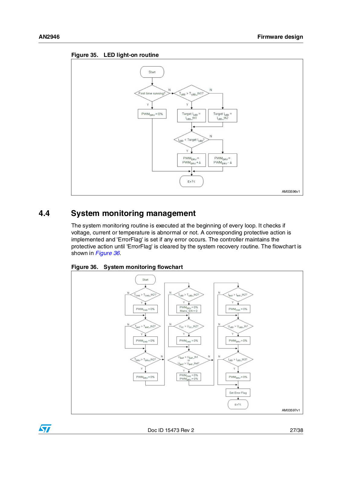
Figure 1. Solar-LED streetlight controller demonstration board. . . . . . . . . . . . . . . . . . . . . . . . . . . . . . 1 Figure 2. Solar-LED streetlight system . . . . . . . . . . . . . . . . . . . . . . . . . . . . . . . . . . . . . . . . . . . . . . . . 6 Figure 3. System block diagram . . . . . . . . . . . . . . . . . . . . . . . . . . . . . . . . . . . . . . . . . . . . . . . . . . . . . 7 Figure 4. Battery charging pattern . . . . . . . . . . . . . . . . . . . . . . . . . . . . . . . . . . . . . . . . . . . . . . . . . . . . 8 Figure 5. LED lamp driving scheme. . . . . . . . . . . . . . . . . . . . . . . . . . . . . . . . . . . . . . . . . . . . . . . . . . . 9 Figure 6. 12 V power supply circuit . . . . . . . . . . . . . . . . . . . . . . . . . . . . . . . . . . . . . . . . . . . . . . . . . . 10 Figure 7. 3.3 V power supply circuit. . . . . . . . . . . . . . . . . . . . . . . . . . . . . . . . . . . . . . . . . . . . . . . . . . 10 Figure 8. Noise filtering circuit for VDD and VDDA . . . . . . . . . . . . . . . . . . . . . . . . . . . . . . . . . . . . . . 11 Figure 9. Solar module control circuit . . . . . . . . . . . . . . . . . . . . . . . . . . . . . . . . . . . . . . . . . . . . . . . . 11 Figure 10. Hardware OVP circuit for battery overcharging protection . . . . . . . . . . . . . . . . . . . . . . . . . 12 Figure 11. Battery charger circuit. . . . . . . . . . . . . . . . . . . . . . . . . . . . . . . . . . . . . . . . . . . . . . . . . . . . . 12 Figure 12. LED lamp driver circuit . . . . . . . . . . . . . . . . . . . . . . . . . . . . . . . . . . . . . . . . . . . . . . . . . . . . 14 Figure 13. Temperature sensing circuits . . . . . . . . . . . . . . . . . . . . . . . . . . . . . . . . . . . . . . . . . . . . . . . 15 Figure 14. Voltage and current detection circuit . . . . . . . . . . . . . . . . . . . . . . . . . . . . . . . . . . . . . . . . . 15 Figure 15. Charging current versus solar module output voltage . . . . . . . . . . . . . . . . . . . . . . . . . . . . 16 Figure 16. MPPT test diagram . . . . . . . . . . . . . . . . . . . . . . . . . . . . . . . . . . . . . . . . . . . . . . . . . . . . . . . 16 Figure 17. V-I curve and PSC . . . . . . . . . . . . . . . . . . . . . . . . . . . . . . . . . . . . . . . . . . . . . . . . . . . . . . . 17 Figure 18. Battery voltage versus charging current . . . . . . . . . . . . . . . . . . . . . . . . . . . . . . . . . . . . . . . 18 Figure 19. Charger input current (Isc) . . . . . . . . . . . . . . . . . . . . . . . . . . . . . . . . . . . . . . . . . . . . . . . . . 19 Figure 20. Charger output current (Iba) . . . . . . . . . . . . . . . . . . . . . . . . . . . . . . . . . . . . . . . . . . . . . . . . 19 Figure 21. Vds on Q2, current on L2, and Vak on D4 . . . . . . . . . . . . . . . . . . . . . . . . . . . . . . . . . . . . . 19 Figure 22. LED lamp current, efficiency vs. battery voltage. . . . . . . . . . . . . . . . . . . . . . . . . . . . . . . . . 19 Figure 23. LED current, efficiency vs. LED voltage . . . . . . . . . . . . . . . . . . . . . . . . . . . . . . . . . . . . . . . 20 Figure 24. Driver input current . . . . . . . . . . . . . . . . . . . . . . . . . . . . . . . . . . . . . . . . . . . . . . . . . . . . . . . 20 Figure 25. Driver output current . . . . . . . . . . . . . . . . . . . . . . . . . . . . . . . . . . . . . . . . . . . . . . . . . . . . . . 20 Figure 26. Vgs, Ids, and Vds on Q4. . . . . . . . . . . . . . . . . . . . . . . . . . . . . . . . . . . . . . . . . . . . . . . . . . . 20 Figure 27. Main loop flowchart. . . . . . . . . . . . . . . . . . . . . . . . . . . . . . . . . . . . . . . . . . . . . . . . . . . . . . . 22 Figure 28. 80 W solar module I-V and P-V curve . . . . . . . . . . . . . . . . . . . . . . . . . . . . . . . . . . . . . . . . 23 Figure 29. P and O method . . . . . . . . . . . . . . . . . . . . . . . . . . . . . . . . . . . . . . . . . . . . . . . . . . . . . . . . . 23 Figure 30. P and O tracing route . . . . . . . . . . . . . . . . . . . . . . . . . . . . . . . . . . . . . . . . . . . . . . . . . . . . . 24 Figure 31. Three-stage charging routine . . . . . . . . . . . . . . . . . . . . . . . . . . . . . . . . . . . . . . . . . . . . . . . 25 Figure 32. MPPT flowchart . . . . . . . . . . . . . . . . . . . . . . . . . . . . . . . . . . . . . . . . . . . . . . . . . . . . . . . . . 25 Figure 33. Ambient light sensing flowchart (day and night judgment) . . . . . . . . . . . . . . . . . . . . . . . . . 26 Figure 34. LED light-off routine . . . . . . . . . . . . . . . . . . . . . . . . . . . . . . . . . . . . . . . . . . . . . . . . . . . . . . 26 Figure 35. LED light-on routine . . . . . . . . . . . . . . . . . . . . . . . . . . . . . . . . . . . . . . . . . . . . . . . . . . . . . . 27 Figure 36. System monitoring flowchart. . . . . . . . . . . . . . . . . . . . . . . . . . . . . . . . . . . . . . . . . . . . . . . . 27 Figure 37. LED_fault IRQ flowchart . . . . . . . . . . . . . . . . . . . . . . . . . . . . . . . . . . . . . . . . . . . . . . . . . . . 28 Figure 38. System self-recovery flowchart. . . . . . . . . . . . . . . . . . . . . . . . . . . . . . . . . . . . . . . . . . . . . . 28 Figure 39. Anti-backflow for battery charging flowchart . . . . . . . . . . . . . . . . . . . . . . . . . . . . . . . . . . . . 29 Figure 40. Schematic . . . . . . . . . . . . . . . . . . . . . . . . . . . . . . . . . . . . . . . . . . . . . . . . . . . . . . . . . . . . . . 30 Figure 41. Top view of demonstration board . . . . . . . . . . . . . . . . . . . . . . . . . . . . . . . . . . . . . . . . . . . . 31 Figure 42. Bottom view of demonstration board . . . . . . . . . . . . . . . . . . . . . . . . . . . . . . . . . . . . . . . . . 31

4/38

Doc ID 15473 Rev 2

AN2946

Safety instructions


1 Safety instructions

Warning: The demonstration board must be used in a suitable laboratory by qualified personnel only who are familiar with the installation, use, and maintenance of electrical systems.

1.1Intended use

The demonstration board is a component designed for demonstration purposes only, and shall be used neither for domestic installation nor for industrial installation. The technical data as well as the information concerning the power supply and operating conditions shall be taken from the documentation included with the demonstration board and strictly observed.

1.2Installation

The installation of the demonstration board shall be taken from the present document and strictly observed. The components must be protected against excessive strain. In particular, no components are to be bent, or isolating distances altered during the transportation, handling or usage. The demonstration board contains electrostatically-sensitive components that are prone to damage through improper use. Electrical components must not be mechanically damaged or destroyed (to avoid potential risks and health injury).

1.3Electrical connection

Applicable national accident prevention rules must be followed when working on the mains power supply. The electrical installation shall be completed in accordance with the appropriate requirements (e.g. cross-sectional areas of conductors, soldering, and PE connections).

1.4Board operation

A system architecture which supplies power to the demonstration board shall be equipped with additional control and protective devices in accordance with the applicable safety requirements (e.g. compliance with technical equipment and accident prevention rules).

Doc ID 15473 Rev 2

5/38

General description

AN2946


2 General description

2.1Controller features

MPPT maximizes solar module efficacy

Automatic day and night detection

Automatic mains switch enable function when battery low

Constant current control for LED lamp

Battery charge control

Optional LED lighting mode

LED indicators for system status monitoring and debugging status

Full protection function for OVP, UVP, OCP, and OTP.

2.2Solar-LED streetlight system architecture

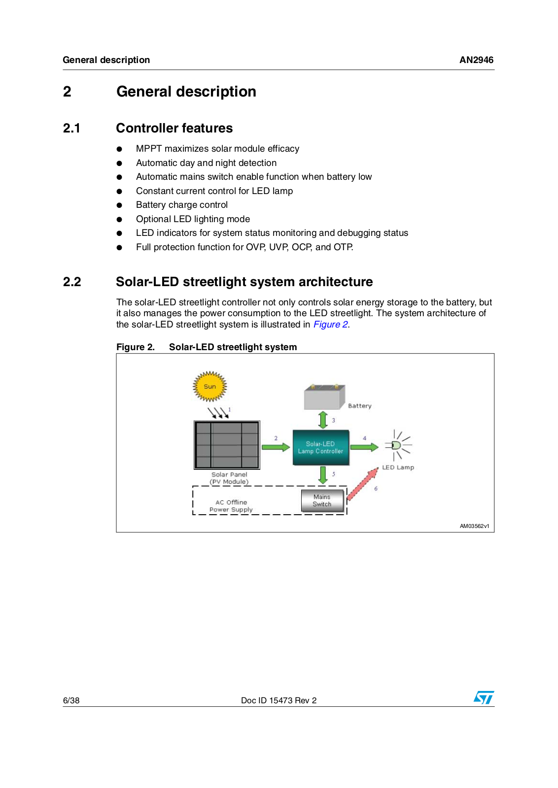
The solar-LED streetlight controller not only controls solar energy storage to the battery, but it also manages the power consumption to the LED streetlight. The system architecture of the solar-LED streetlight system is illustrated in Figure 2.

Figure 2. Solar-LED streetlight system

!-V

6/38

Doc ID 15473 Rev 2

AN2946

General description


1.The sunlight delivers rays of photons (solar energy) which hit the solar panel (Photovoltaic or PV module). The photons (energy) are absorbed by the PV and electrons are released.

2.The electrons flow along the metal contact of the PV and form electricity.

3.Energy is stored in the battery during daytime and consumed at night.

4.The LED lamp (LED streetlight) is driven to operate by the LED lamp driver. This controller monitors the system and manages the light-on and light-off in day and night time.

5.When the battery goes low, the controller sends an enable signal to the 'Mains switch' which enables the AC offline power supply.

6.The AC offline power supply (not included in this application note) works as a backup source to power the LED streetlight.

2.3Scope of the solar-LED streetlight controller

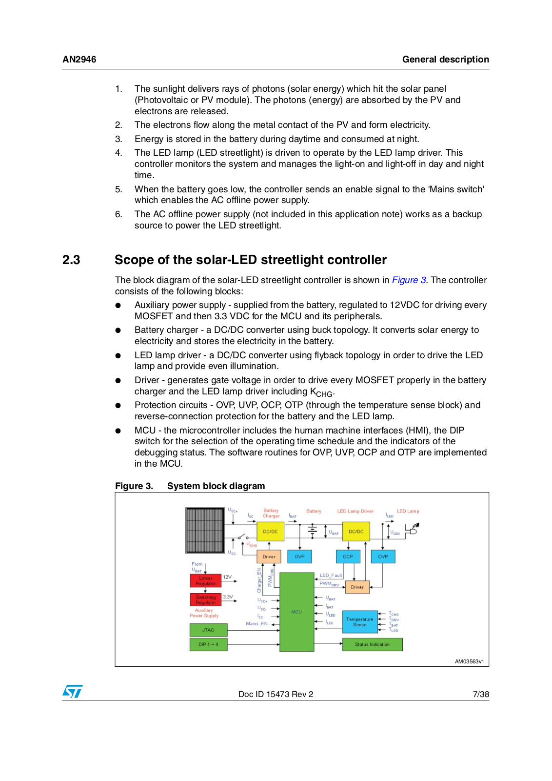
The block diagram of the solar-LED streetlight controller is shown in Figure 3. The controller consists of the following blocks:

Auxiliary power supply - supplied from the battery, regulated to 12VDC for driving every MOSFET and then 3.3 VDC for the MCU and its peripherals.

Battery charger - a DC/DC converter using buck topology. It converts solar energy to electricity and stores the electricity in the battery.

LED lamp driver - a DC/DC converter using flyback topology in order to drive the LED lamp and provide even illumination.

Driver - generates gate voltage in order to drive every MOSFET properly in the battery charger and the LED lamp driver including KCHG.

Protection circuits - OVP, UVP, OCP, OTP (through the temperature sense block) and reverse-connection protection for the battery and the LED lamp.

MCU - the microcontroller includes the human machine interfaces (HMI), the DIP switch for the selection of the operating time schedule and the indicators of the debugging status. The software routines for OVP, UVP, OCP and OTP are implemented in the MCU.

Figure 3. System block diagram

!-V

Doc ID 15473 Rev 2

7/38

General description

AN2946


The MCU implements the sophisticated peripherals as listed in Table 1.

Table 1.

MCU peripheral allocation


Peripheral

Number


Description


ADC

11

USC+, USC-, UBAT, ULED, ISC, IBAT, ILED, TCHG, TBAT, TDRV, TLED

GPIO

12

Inputs

DIP1~4 (up to 16 modes) JTAG


Charger_EN for anti-backflow charge


Status indication

Mains_EN for switching to mains supply


Battery LED1-2 for indicating battery status


Debug LED1-4 for diagnosis (up to 16 messages)


PWM

2


PWMCHG, PWMDRV (100 kHz)

EXT1

1


LED fault


2.4Main functions of the controller

2.4.1Battery charging management

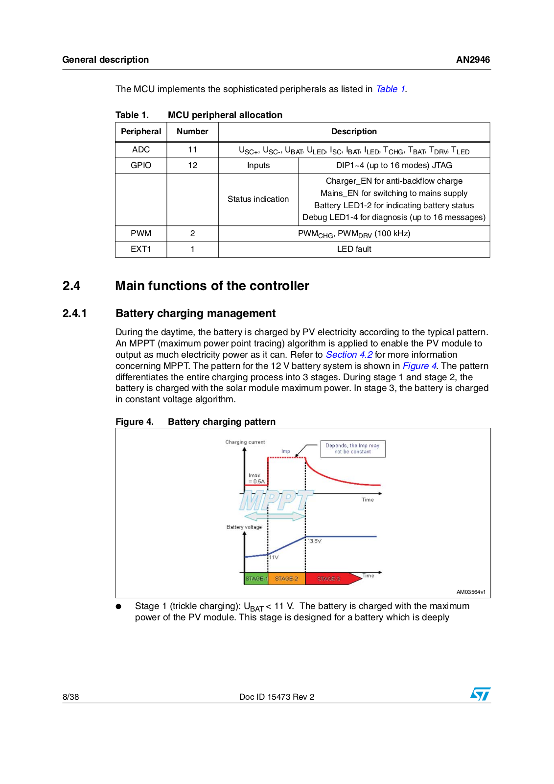
During the daytime, the battery is charged by PV electricity according to the typical pattern. An MPPT (maximum power point tracing) algorithm is applied to enable the PV module to output as much electricity power as it can. Refer to Section 4.2 for more information concerning MPPT. The pattern for the 12 V battery system is shown in Figure 4. The pattern differentiates the entire charging process into 3 stages. During stage 1 and stage 2, the battery is charged with the solar module maximum power. In stage 3, the battery is charged in constant voltage algorithm.

Figure 4. Battery charging pattern

!-V

Stage 1 (trickle charging): UBAT < 11 V. The battery is charged with the maximum power of the PV module. This stage is designed for a battery which is deeply

8/38

Doc ID 15473 Rev 2

AN2946

General description


discharged. In order to prolong battery operating life, the charging current is constrained at Imax = 0.5 A.

Stage 2 (high-current bulk charging): 11 V ≤ UBAT < 14.3 V. In this stage, the battery is charged with the maximum power of the PV module. The charging current (Imp) may not be constant.

Stage 3 (floating charging): UBAT ≥ 14.3 V. In this stage, battery is charged at constant voltage (14.3 V).

The voltage values 11 V and 14.3 V define the boundaries of the stages that are based on the characteristics of a typical 12 V lead acid battery. The voltage needed depends on the type of battery.

2.4.2LED lamp driving management

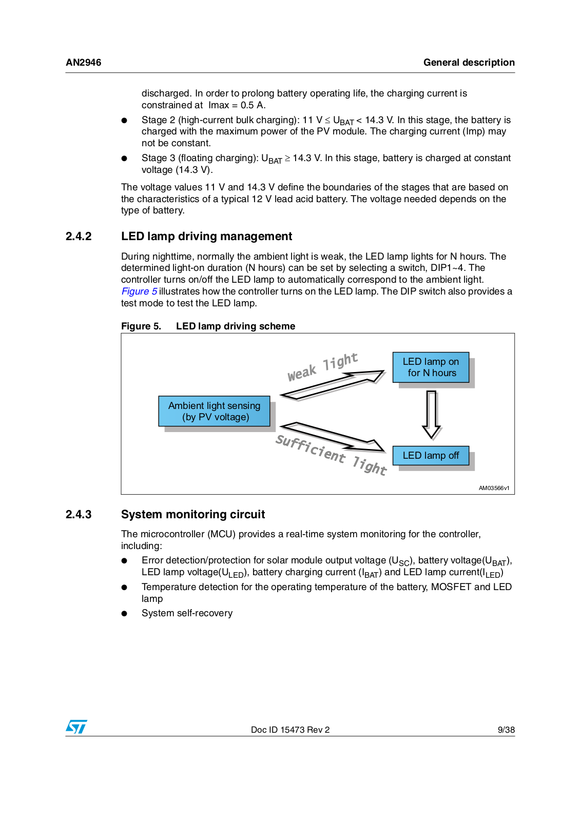
During nighttime, normally the ambient light is weak, the LED lamp lights for N hours. The determined light-on duration (N hours) can be set by selecting a switch, DIP1~4. The controller turns on/off the LED lamp to automatically correspond to the ambient light. Figure 5 illustrates how the controller turns on the LED lamp. The DIP switch also provides a test mode to test the LED lamp.

Figure 5. LED lamp driving scheme


/(' ODPS RQ


IRU 1 KRXUV

$PELHQW OLJKW VHQVLQJ E\ 39 YROWDJH

/(' ODPS RII

!-V

2.4.3System monitoring circuit

The microcontroller (MCU) provides a real-time system monitoring for the controller, including:

Error detection/protection for solar module output voltage (USC), battery voltage(UBAT), LED lamp voltage(ULED), battery charging current (IBAT) and LED lamp current(ILED)

Temperature detection for the operating temperature of the battery, MOSFET and LED lamp

System self-recovery

Doc ID 15473 Rev 2

9/38

Hardware design

AN2946


3 Hardware design

3.1Circuit description

3.1.1Power supply circuit

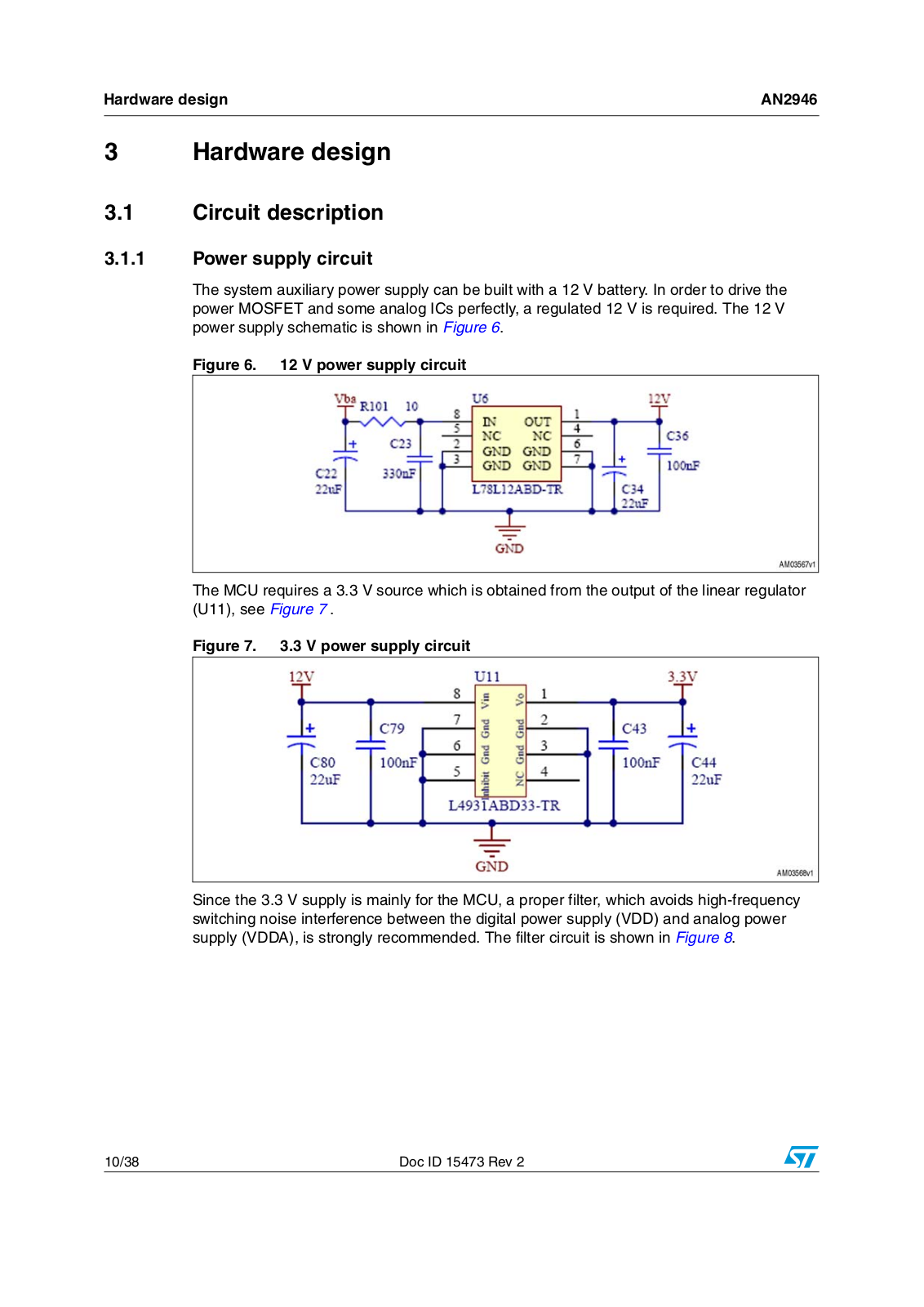
The system auxiliary power supply can be built with a 12 V battery. In order to drive the power MOSFET and some analog ICs perfectly, a regulated 12 V is required. The 12 V power supply schematic is shown in Figure 6.

Figure 6. 12 V power supply circuit

The MCU requires a 3.3 V source which is obtained from the output of the linear regulator (U11), see Figure 7 .

Figure 7. 3.3 V power supply circuit

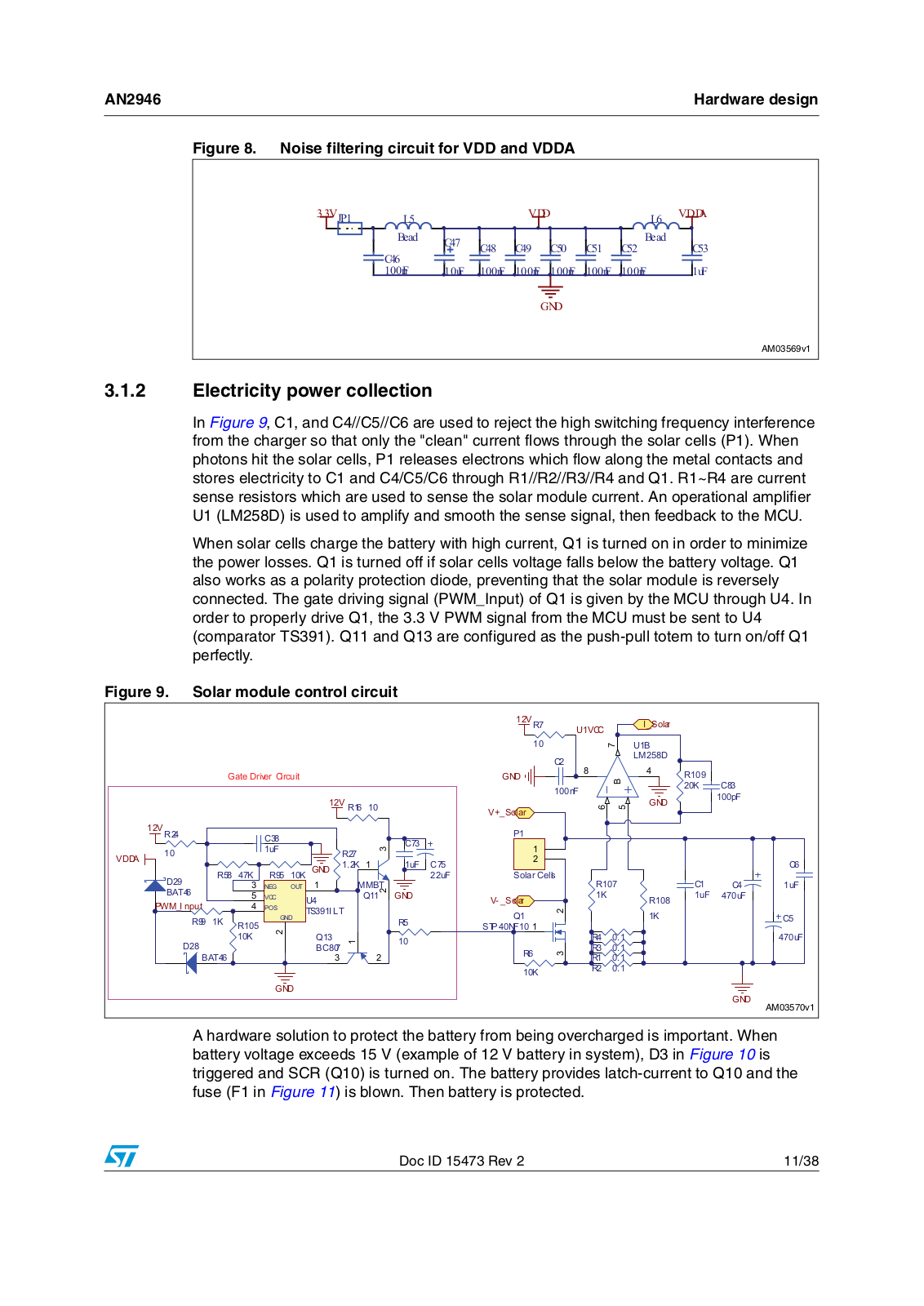
Since the 3.3 V supply is mainly for the MCU, a proper filter, which avoids high-frequency switching noise interference between the digital power supply (VDD) and analog power supply (VDDA), is strongly recommended. The filter circuit is shown in Figure 8.

10/38

Doc ID 15473 Rev 2

AN2946

Hardware design


Figure 8. Noise filtering circuit for VDD and VDDA

9-3

/


9''


/

9''$


%HDG

&


%HDG


&

&

&

&

&

&


&


Q)

X)

Q)

Q)

Q)

Q)

Q)

X)


*1'


!-V

3.1.2Electricity power collection

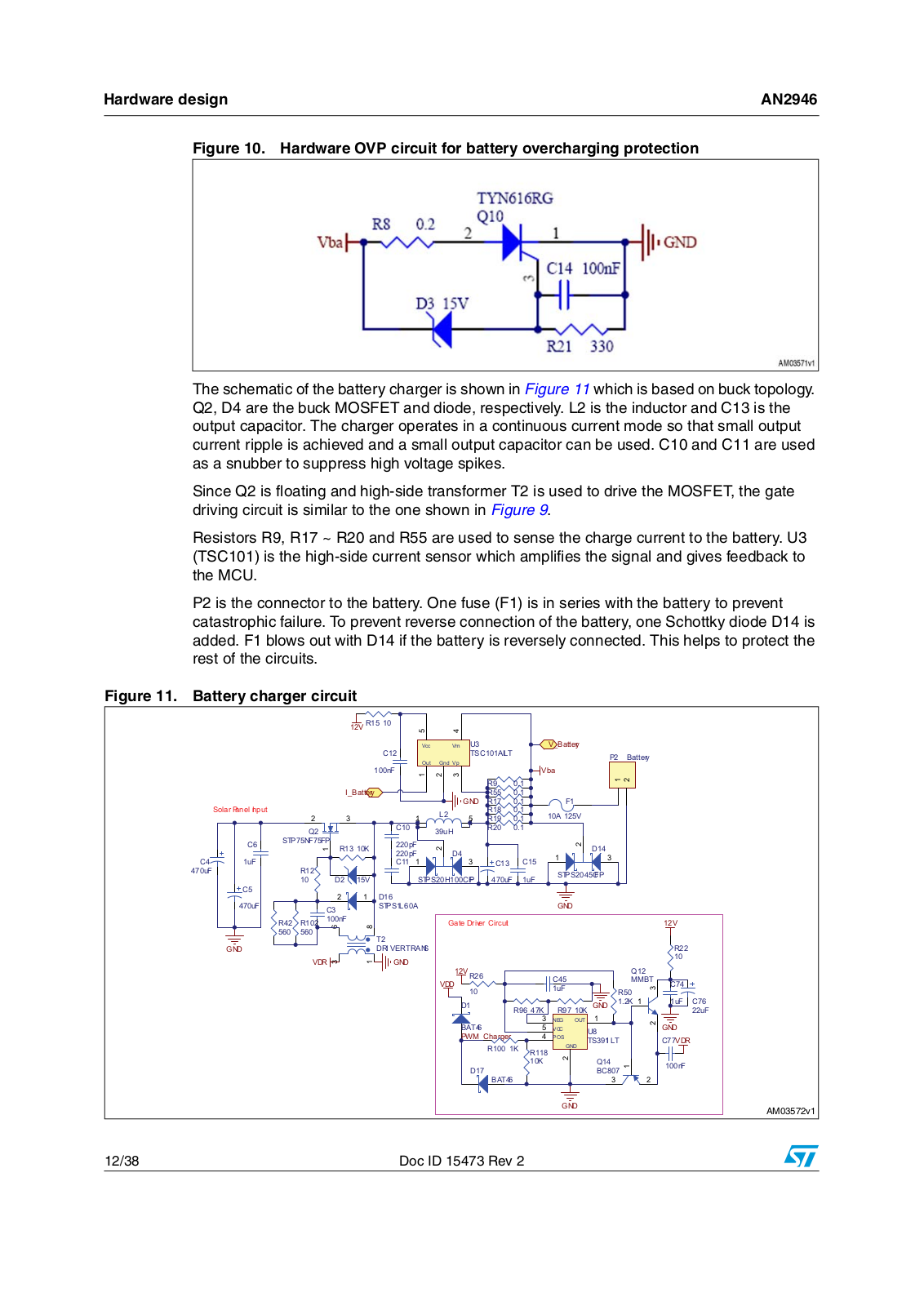
In Figure 9, C1, and C4//C5//C6 are used to reject the high switching frequency interference from the charger so that only the "clean" current flows through the solar cells (P1). When photons hit the solar cells, P1 releases electrons which flow along the metal contacts and stores electricity to C1 and C4/C5/C6 through R1//R2//R3//R4 and Q1. R1~R4 are current sense resistors which are used to sense the solar module current. An operational amplifier U1 (LM258D) is used to amplify and smooth the sense signal, then feedback to the MCU.

When solar cells charge the battery with high current, Q1 is turned on in order to minimize the power losses. Q1 is turned off if solar cells voltage falls below the battery voltage. Q1 also works as a polarity protection diode, preventing that the solar module is reversely connected. The gate driving signal (PWM_Input) of Q1 is given by the MCU through U4. In order to properly drive Q1, the 3.3 V PWM signal from the MCU must be sent to U4 (comparator TS391). Q11 and Q13 are configured as the push-pull totem to turn on/off Q1 perfectly.

Figure 9. Solar module control circuit


9 5


8 9&&


,B6RODU


8 %


&


/0 '


*DWH 'ULYHU &LUFXLW


*1'


%

5


Q)


.

&


9 5


*1'


S)


9 B6RODU


9 5


&


&


3


X)


5


9''$


. *1'

.


X)

&


&

'

5

.

5


X)

6RODU &HOOV

5


&


X)


1(*

287


00%7


&

%$7


9&&


8


4


*1'


9 B6RODU


.


5

X)

X)


3:0B, QSXW


326


76 , /7


4


.


&

5

.


*1'


5


5


673 1)


.


4


5


X)

'


%&


5


5


%$7


5


.


5


*1'


*1'


!-V


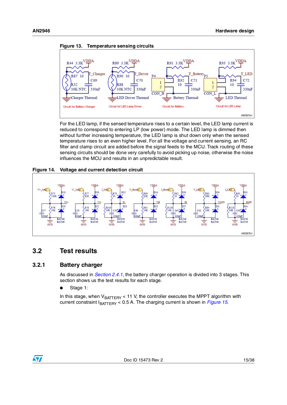
A hardware solution to protect the battery from being overcharged is important. When battery voltage exceeds 15 V (example of 12 V battery in system), D3 in Figure 10 is triggered and SCR (Q10) is turned on. The battery provides latch-current to Q10 and the fuse (F1 in Figure 11) is blown. Then battery is protected.

Doc ID 15473 Rev 2

11/38

ST AN2946 Application note

Hardware design

AN2946


Figure 10. Hardware OVP circuit for battery overcharging protection

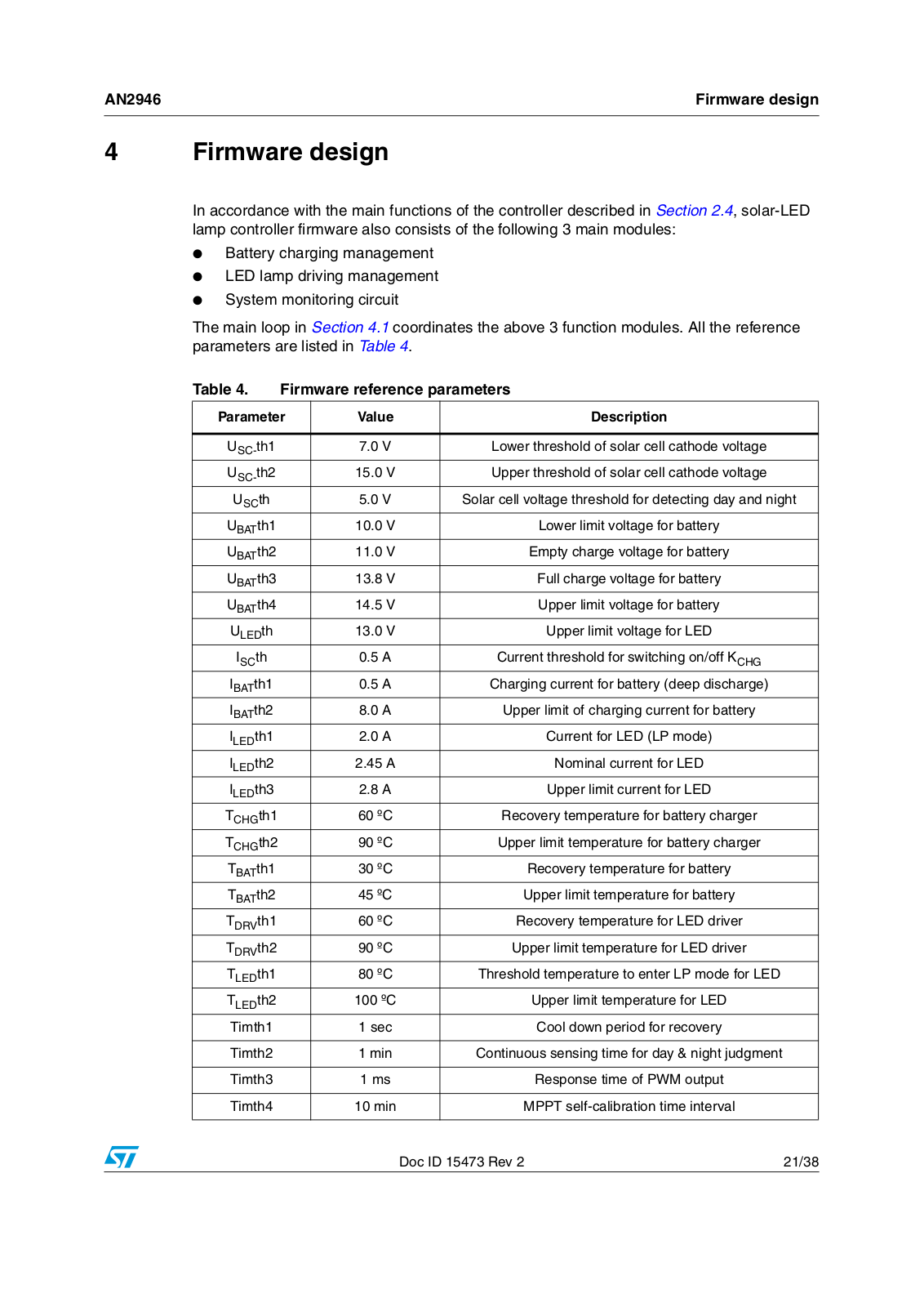
The schematic of the battery charger is shown in Figure 11 which is based on buck topology. Q2, D4 are the buck MOSFET and diode, respectively. L2 is the inductor and C13 is the output capacitor. The charger operates in a continuous current mode so that small output current ripple is achieved and a small output capacitor can be used. C10 and C11 are used as a snubber to suppress high voltage spikes.

Since Q2 is floating and high-side transformer T2 is used to drive the MOSFET, the gate driving circuit is similar to the one shown in Figure 9.

Resistors R9, R17 ~ R20 and R55 are used to sense the charge current to the battery. U3 (TSC101) is the high-side current sensor which amplifies the signal and gives feedback to the MCU.

P2 is the connector to the battery. One fuse (F1) is in series with the battery to prevent catastrophic failure. To prevent reverse connection of the battery, one Schottky diode D14 is added. F1 blows out with D14 if the battery is reversely connected. This helps to protect the rest of the circuits.

Figure 11. Battery charger circuit


9 5


9FF


9P

8


9B%DWWHU\


&


76&$,/7


3


%DWWHU\


2XW

*QG 9S


Q)


9ED


5


,B%DWWHU\


5


6RODU 3DQHO ,QSXW


*1'

5


)


/


5


$ 9


5


4


&


X+


5


&

673 1) )3

5 .

S)


'


S)

'


&

X)


&


&

&


5


X)


6736 &)3


'

9


6736 + &)

X)

X)


&


'


X)


&


6736 /$


*1'


5

5

Q)


*DWH 'ULYHU &LUFXLW


9


7


*1'


'5, 9(5 75$16


5


9'5


*1'


95


4


&


9''


00%7

&


X)


5


'


5 . *1'

.


X)

&


5 .


X)


%$7


1(*

287


9&&


8


*1'


3:0B&KDUJHU


326


76 , /7


&9'5


5 .


*1'


5


.


4


Q)


'


%&


%$7


*1'


!-V


12/38

Doc ID 15473 Rev 2

Loading...
+ 26 hidden pages