ST AN2945 Application note

AN2645

Application note

Migration and compatibility guidelines for STM8S microcontroller applications

Introduction

For designers of STM8S microcontroller applications, it’s important to be able to easily replace one microcontroller type by another one in the same product family. Migrating an application to a different microcontroller is often needed, when product requirements grow, putting extra demands on memory size, or increasing the number of I/Os. On the other hand, cost reduction objectives may force you to switch to smaller components and shrink the PCB area. This application note is written to help you and analyze the steps you need to migrate from an existing STM8S-based design to any one of the 20+ other microcontroller types in the fast-growing STM8S family.

To save your time, this application note groups together all the most important information and lists the vital aspects that you need to address.

All the information included here can also be extremely worthwhile in your first STM8 design, not immediately concerned by a migration project. Studying the issues now will help you tackle any future requirement by designing for compatibility from the beginning. To use this application note fully, general STM8S knowledge is required, you can learn it from the STM8S family reference manual (RM0016), the STM8S datasheets, and the STM8S Flash program memory / data EEPROM programming manual (PM0051).

This document is divided into three main sections:

Section 1: STM8S family compatibility: This section presents a first level view of the different aspects of the STM8S family architecture that are important to consider when planning a new design or migrating. The microcontroller blocks and peripherals are grouped and identified either as compatible or compatible with minor limitations.

Section 2: Planning for migration: This section gives an overview of common migration cases. It provides a checklist of items which are potentially impacted by each case to allow you to quickly analyze which subjects you need to anticipate.

Section 3: Block-by-block compatibility: This section lists all the topics for each block, focussing on the compatibility aspects in more detail.

March 2009

Rev 1

1/36

www.st.com

Contents

AN2645


Contents

1

STM8S family compatibility . . . . . . . . . . . . . . . . . . . . . . . . . . . . . . . . . .

. 6


1.1

Family concept . . . . . . . . . . . . . . . . . . . . . . . . . . . . . . . . . . . . . . . . . . . . . .

6


1.2

Fully compatible blocks . . . . . . . . . . . . . . . . . . . . . . . . . . . . . . . . . . . . . . .

7


1.3

Blocks that are compatible with minor exceptions . . . . . . . . . . . . . . . . . . .

7


1.4

Blocks that are compatible with significant exceptions . . . . . . . . . . . . . . . .

8

2

Planning for migration . . . . . . . . . . . . . . . . . . . . . . . . . . . . . . . . . . . . . .

10

3

Block-by-block compatibility analysis . . . . . . . . . . . . . . . . . . . . . . . . .

12


3.1

Package pinout . . . . . . . . . . . . . . . . . . . . . . . . . . . . . . . . . . . . . . . . . . . . .

12


3.1.1

Migration from one sub-family to another one . . . . . . . . . . . . . . . . . . . .

13

3.1.2Migration to a package with different pin-count within the same sub-family 15


3.1.3

System pins and package pinout . . . . . . . . . . . . . . . . . . . . . . . . . . . . . .

18


3.1.4

Digital power supply and package pinout . . . . . . . . . . . . . . . . . . . . . . .

20


3.1.5

ADC power supply and voltage reference in package pinout . . . . . . . .

20


3.1.6

Alternate functions and package pinout . . . . . . . . . . . . . . . . . . . . . . . . .

22

3.2

Digital I/O . . . . . . . . . . . . . . . . . . . . . . . . . . . . . . . . . . . . . . . . . . . . . . . . .

23

3.2.1 GPIO . . . . . . . . . . . . . . . . . . . . . . . . . . . . . . . . . . . . . . . . . . . . . . . . . . . 23 3.2.2 High-sink capability . . . . . . . . . . . . . . . . . . . . . . . . . . . . . . . . . . . . . . . . 24 3.2.3 External interrupts . . . . . . . . . . . . . . . . . . . . . . . . . . . . . . . . . . . . . . . . . 24

3.3 Timers . . . . . . . . . . . . . . . . . . . . . . . . . . . . . . . . . . . . . . . . . . . . . . . . . . . 25 3.4 Analog-to-digital converter . . . . . . . . . . . . . . . . . . . . . . . . . . . . . . . . . . . . 26

3.4.1 ADC inputs . . . . . . . . . . . . . . . . . . . . . . . . . . . . . . . . . . . . . . . . . . . . . . . 26 3.4.2 ADC supply and reference pins . . . . . . . . . . . . . . . . . . . . . . . . . . . . . . . 26 3.4.3 ADC modes . . . . . . . . . . . . . . . . . . . . . . . . . . . . . . . . . . . . . . . . . . . . . . 27

3.5

Communication peripherals . . . . . . . . . . . . . . . . . . . . . . . . . . . . . . . . . . .

28


3.5.1

SPI . . . . . . . . . . . . . . . . . . . . . . . . . . . . . . . . . . . . . . . . . . . . . . . . . . . . .

28


3.5.2

I2C . . . . . . . . . . . . . . . . . . . . . . . . . . . . . . . . . . . . . . . . . . . . . . . . . . . . .

28


3.5.3

CAN . . . . . . . . . . . . . . . . . . . . . . . . . . . . . . . . . . . . . . . . . . . . . . . . . . . .

28


3.5.4

UART . . . . . . . . . . . . . . . . . . . . . . . . . . . . . . . . . . . . . . . . . . . . . . . . . . .

29

3.6 Clock controller . . . . . . . . . . . . . . . . . . . . . . . . . . . . . . . . . . . . . . . . . . . . . 30

3.6.1 HSE clock frequency . . . . . . . . . . . . . . . . . . . . . . . . . . . . . . . . . . . . . . . 30 3.6.2 HSI clock frequency . . . . . . . . . . . . . . . . . . . . . . . . . . . . . . . . . . . . . . . . 30

2/36

AN2645 Contents


3.7

Memory

. . . . . . . . . . . . . . . . . . . . . . . . . . . . . . . . . . . . . . . . . . . . . . . . . .

30


3.7.1

Flash program memory . . . . . . . . . . . . . . . . . . . . . . . . . . . . . . . . . . . . .

30


3.7.2

EEPROM data memory . . . . . . . . . . . . . . . . . . . . . . . . . . . . . . . . . . . . .

31


3.7.3

BootROM memory . . . . . . . . . . . . . . . . . . . . . . . . . . . . . . . . . . . . . . . . .

32


3.7.4

RAM memory . . . . . . . . . . . . . . . . . . . . . . . . . . . . . . . . . . . . . . . . . . . . .

32


3.7.5

Stack . . . . . . . . . . . . . . . . . . . . . . . . . . . . . . . . . . . . . . . . . . . . . . . . . . .

32


3.7.6

GPIO and peripheral registers . . . . . . . . . . . . . . . . . . . . . . . . . . . . . . . .

33


3.7.7

Interrupt mapping . . . . . . . . . . . . . . . . . . . . . . . . . . . . . . . . . . . . . . . . . .

33


3.7.8

Option bytes . . . . . . . . . . . . . . . . . . . . . . . . . . . . . . . . . . . . . . . . . . . . . .

34

4

Revision history . . . . . . . . . . . . . . . . . . . . . . . . . . . . . . . . . . . . . . . . . . .

35

3/36

List of tables

AN2645


List of tables

Table 1. STM8S family compatibility quick reference table . . . . . . . . . . . . . . . . . . . . . . . . . . . . . . . 11 Table 2. Overview of packages in each sub-family . . . . . . . . . . . . . . . . . . . . . . . . . . . . . . . . . . . . . 12 Table 3. Migration between STM8S208 and STM8S207 80-pin or 64-pin packages . . . . . . . . . . . . 13 Table 4. Migration between STM8S207 and STM8S105 48-pin or 44-pin packages . . . . . . . . . . . . 13 Table 5. Migration between STM8S207 and STM8S105 32-pin packages . . . . . . . . . . . . . . . . . . . 13 Table 6. Migration between STM8S105 and STM8S103 32-pin packages . . . . . . . . . . . . . . . . . . . 14 Table 7. Migration between STM8S105 and STM8S903 32-pin packages . . . . . . . . . . . . . . . . . . . 14 Table 8. Migration between STM8S903 and STM8S103 32-pin packages . . . . . . . . . . . . . . . . . . . 15 Table 9. STM8S20xx migration between 80-pin and 64-pin packages . . . . . . . . . . . . . . . . . . . . . . 15 Table 10. STM8S207x migration between 64-pin and 48-pin packages . . . . . . . . . . . . . . . . . . . . . . 16 Table 11. STM8S207x migration between 48-pin and 44-pin packages . . . . . . . . . . . . . . . . . . . . . . 16 Table 12. STM8S207x migration between 44-pin and 32-pin packages . . . . . . . . . . . . . . . . . . . . . . 16 Table 13. STM8105x migration between 48-pin and 44-pin packages. . . . . . . . . . . . . . . . . . . . . . . . 17 Table 14. STM8S105x migration between 44-pin and 32-pin packages . . . . . . . . . . . . . . . . . . . . . . 17 Table 15. STM8S103x migration between 32-pin and 20-pin packages . . . . . . . . . . . . . . . . . . . . . . 18 Table 16. Overview of power supply pins used in all packages . . . . . . . . . . . . . . . . . . . . . . . . . . . . . 20 Table 17. Overview of ADC supply and ADC reference pins used in all packages . . . . . . . . . . . . . . 21 Table 18. Total number of GPIOs in each package . . . . . . . . . . . . . . . . . . . . . . . . . . . . . . . . . . . . . . 23 Table 19. Total number of high sink I/Os in each package. . . . . . . . . . . . . . . . . . . . . . . . . . . . . . . . . 24 Table 20. Total number of external interrupt pins in each package . . . . . . . . . . . . . . . . . . . . . . . . . . 24 Table 21. Total number of timer channels (direct I/Os + complementary outputs) in each package . 25 Table 22. Total number of analog inputs in each package . . . . . . . . . . . . . . . . . . . . . . . . . . . . . . . . . 26 Table 23. Overview of ADC mode differences . . . . . . . . . . . . . . . . . . . . . . . . . . . . . . . . . . . . . . . . . . 27 Table 24. UART special features . . . . . . . . . . . . . . . . . . . . . . . . . . . . . . . . . . . . . . . . . . . . . . . . . . . . 29 Table 25. Flash program memory size in bytes for each package/sub-family . . . . . . . . . . . . . . . . . . 31 Table 26. Flash program memory granularity in each sub-family . . . . . . . . . . . . . . . . . . . . . . . . . . . . 31 Table 27. Data EEPROM memory size in bytes for each sub-family/Flash size . . . . . . . . . . . . . . . . 32 Table 28. Data EEPROM memory granularity in each sub-family . . . . . . . . . . . . . . . . . . . . . . . . . . . 32 Table 29. RAM memory size (bytes) for each sub-family/Flash size . . . . . . . . . . . . . . . . . . . . . . . . . 32 Table 30. Interrupt vector table differences . . . . . . . . . . . . . . . . . . . . . . . . . . . . . . . . . . . . . . . . . . . . 33 Table 31. Document revision history . . . . . . . . . . . . . . . . . . . . . . . . . . . . . . . . . . . . . . . . . . . . . . . . . 35

4/36

AN2645

List of figures


List of figures

Figure 1. STM8S family block diagram . . . . . . . . . . . . . . . . . . . . . . . . . . . . . . . . . . . . . . . . . . . . . . . . 9 Figure 2. STM8S pinout compatibility guide from 80-pin to 20-pin packages . . . . . . . . . . . . . . . . . . 19

5/36

STM8S family compatibility

AN2645


1 STM8S family compatibility

1.1Family concept

The STM8S family is one of a growing number of different STM8 microcontroller families.

All these STM8 microcontroller families are based on common robust and low cost 8-bit high performance core with rich set of enhanced peripherals. This ensures high level of compatibility within the STM8 ‘world’, especially in terms of software development, compilers, debugging environment, programming tools and driver libraries.

The STM8S product family offers a wide choice of memory sizes and package types to fit different application requirements as closely as possible. So when there are new requirements on the application side, it can make sense to switch to another STM8S type with different memory capacity or package size.

The STM8S family is divided into two product lines, and within each product line there are two main sub-families:

STM8S Performance line includes STM8S208 and STM8S207 sub-families

STM8S Access line includes STM8S105 and STM8S103 sub-families

The STM8S family also includes some application-specific microcontrollers (ASSM) like the STM8S903 which is derived from the STM8S103 sub-family and which has extra features.

Both main product lines provide a complete set of essential peripherals. STM8S Access line targets applications requiring reduced cost, lower memory capacity, fewer GPIOs and less advanced features.

The wide range of available pin-counts and package sizes is discussed in Chapter 3.1: Package pinout.

All STM8S family microcontrollers use the same application development tools:

Embedded single wire interface module (SWIM)

Software integrated development environment (IDE) tools including assembler, simulator, debugger, programmer:

ST Visual Develop (ST)

Ride (Raisonance)

In-circuit debugging and programming tools

STIce from ST (full hardware emulator)

RLink from Raisonance (low cost debug/programming tool)

Starter kits and evaluation boards

C compiler and assembler tool chains (Cosmic, Raisonance)

Firmware libraries (peripheral control examples, MISRA or class B compliance, touch sensing)

Application notes

By using a common development environment, you significantly reduce code maintenance effort and shorten the time-to-market, especially in cases when an application has to be migrated from one STM8 microcontroller to another.

By using the drivers provided in the STM8S firmware library to interface with the hardware, it becomes reasonably straightforward to move the application firmware from one STM8S

6/36

AN2645

STM8S family compatibility


product to another. The principle job is analyzing the details on the hardware side, taking care of the placement and availability of the peripheral I/O functions in the pinout. Details about this can be obtained in the STM8S datasheet and further in this document in

Section 3.1: Package pinout.

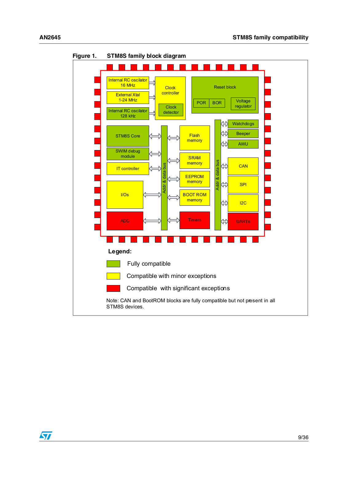
Figure 1: STM8S family block diagram gives an overview of the STM8S blocks and their compatibility level, as discussed further in the next sections.

1.2Fully compatible blocks

The STM8S family embeds a set of system blocks which are by definition common to all products. Those blocks are identical, so they have the same structure, registers and control bits. There is no need to perform any software change to keep the same functionality at the application level after migration. When external components are needed (e.g. Vcap capacitor) no change is required from one product to an other. All the features and behavior remain the same. These blocks are printed in green in Figure 1.

Fully compatible parts and peripherals are:

STM8 core

Debug / SWIM module

Power on Reset and Brownout reset (POR & BOR)

Voltage regulator

Low speed internal RC (LSI)

Independent watchdog, Window watchdog

Auto wakeup timer (AWU) and Beeper unit

1.3Blocks that are compatible with minor exceptions

Some of the peripherals or functional blocks can have differences in their electrical parameters, structure, registers, control bits or other minor aspects but not in their main functionality. The CAN peripheral is not available in all STM8S devices, so this aspect can be considered as an incompatibility, too.

The following functional blocks can be considered as compatible with only a few negligible differences:

Interrupt management (interrupt vectors)

Power control (wake up from low power mode)

GPIO (I/O capabilities)

SPI (max speed)

I2C (true open drain)

CAN (available only in STM8S208x subfamily)

Clock controller with internal RC oscillators (accuracy, calibration)

Internal memories (FLASH, SRAM, EEPROM, boot ROM - size & organization)

You can find more details about these blocks in Chapter 3: Block-by-block compatibility analysis. They are shown in yellow in Figure 1.

7/36

STM8S family compatibility

AN2645


1.4Blocks that are compatible with significant exceptions

A few peripherals have additional features or lack important functionality compared to the same peripheral in other STM8S sub-families. For these particular peripherals you have to adapt the software drivers and check all possible hardware dependencies.

The peripheral and functional blocks in the following list are compatible with significant exceptions. The package pinout is high on the list, as this aspect requires special attention:

Package pinout

ADC

UART

Timers

You can find more details in Section 3: Block-by-block compatibility analysis. These blocks are shown in red in Figure 1.

8/36

ST AN2945 Application note

AN2645

STM8S family compatibility


Figure 1. STM8S family block diagram

Internal RC oscilator


16 MHz

Clock


Reset block


External Xtal

controller


1-24 MHz


POR

BOR

Voltage


Clock

regulator

Internal RC oscilator


detector


128 kHz


Watchdogs

STM8S Core


Flash


Beeper


memory


AWU


SWIM debug


module


SRAM

& data bus


IT controller

data bus

memory

CAN


EEPROM


memory


Addr &

Addr

SPI


I/Os

BOOT ROM


memory


I2C


ADC


Timers


UARTs

Legend:

Fully compatible

Compatible with minor exceptions

Compatible with significant exceptions

Note: CAN and BootROM blocks are fully compatible but not present in all

STM8S devices.

9/36

Planning for migration

AN2645


2 Planning for migration

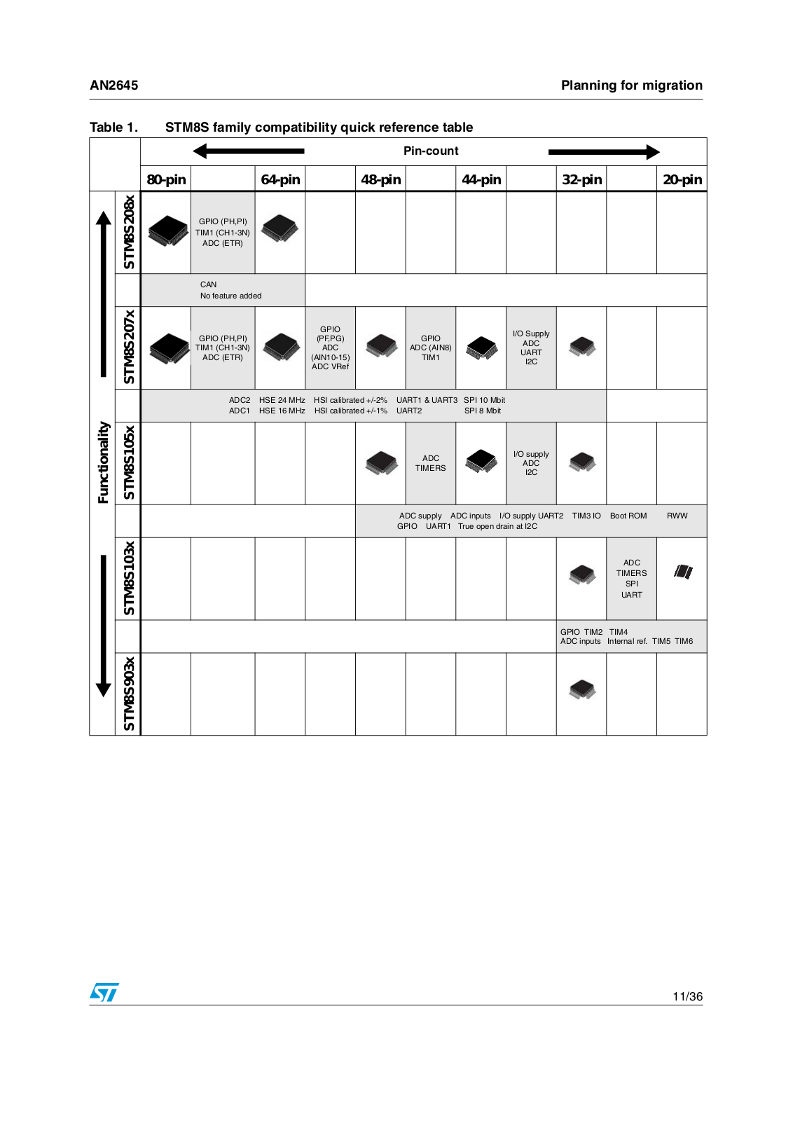
You can use Table 1: STM8S family compatibility quick reference table as a starting point for planning any migration from one STM8S microcontroller to another. This table shows the available migration choices and indicates the features that need special attention in each case.

The table is intended to be used as follows:

Sub-families are listed in rows. Moving between the rows means changing the subfamily.

Available package sizes are listed in columns. Moving between columns means changing the pin-count.

The gray fields represent the migration between each column or row and give the impacted features.

The impact of moves between two subfamilies is common for all available package pairs. Therefore all gray cells in rows are merged into common fields. The text in these common fields is divided into two lines:

When migrating upward: the upper line lists the impact of added features and the lower line lists the features that are lost due to the migration.

When migrating downward, the lower line lists the added features and the upper lines lists the features that are lost.

A move to the right towards smaller packages mainly leads to a loss of I/O pins and their related alternate functions. So the content of these cells is a simple list of impacted items only.

This section mainly discusses cases of migration between neighboring pairs. However your project may be a migration over several rows or columns in Table 1 or even in a diagonal direction. In this case, you should check the differences indicated in each step passed by the vertical and horizontal moves through the table.

Getting started:

1.Specify the migration pair and the direction of the migration, with reference to Table 1.

2.In Table 1, find the gray cell between the selected migration pair.

3.Check here the list of items impacted by any difference in given direction.

4.Check the corresponding paragraph of Chapter 3: Block-by-block compatibility analysis for each of items listed there.

5.Check appropriate datasheets and reference manual for more details.

10/36

AN2645

Planning for migration


Table 1. STM8S family compatibility quick reference table


STM8S208x


STM8S207x

Functionality

STM8S105x


STM8S103x


STM8S903x


Pin-count

80-pin

64-pin

48-pin

44-pin

32-pin


20-pin

GPIO (PH,PI)


TIM1 (CH1-3N)


ADC (ETR)


CAN


No feature added


GPIO


I/O Supply


GPIO (PH,PI)


(PF,PG)

GPIO


ADC


TIM1 (CH1-3N)


ADC

ADC (AIN8)


UART


ADC (ETR)


(AIN10-15)

TIM1


I2C


ADC VRef


ADC2

HSE 24 MHz

HSI calibrated +/-2%

UART1 & UART3

SPI 10 Mbit


ADC1

HSE 16 MHz

HSI calibrated +/-1%

UART2

SPI 8 Mbit


ADC

I/O supply


ADC


TIMERS


I2C


ADC supply ADC inputs I/O supply UART2 TIM3 IO

Boot ROM

RWW


GPIO UART1

True open drain at I2C


ADC


TIMERS


SPI


UART


GPIO TIM2

TIM4


ADC inputs

Internal ref. TIM5 TIM6

11/36

Loading...
+ 25 hidden pages