

Page 1
AN2927
Application note
RC acquisition principle for touch sensing applications
Introduction
In applications requiring user interface, capacitive touch-sensitive controls are becoming the
solution of choice to replace conventional electro-mechanical switches.
STMicroelectronics has developed a complete touch-sensing software library to transform
any 8-bit STM8 microcontroller into a capacitive touchkey controller. For more details,
please go to www.st.com/mcu
This touch sensing software library allows to detect human touch by controlling the
charge/discharge timing cycle of a RC network formed by a single resistor and the touch
electrode capacitance. Any variation in the RC timing due to the electrode capacity change
is detected then filtered and eventually reported to a host system using dedicated I/Os or
2
I
C/SPI interface.
The bill of material is low-cost as only one resistor is needed per touch channel to enable
this function.
The scope of this application note is to describe the RC time constant acquisition principle
used in the touch sensing software library.
Abbreviations
Table 1. List of terms
Acronym Description
EMI Electromagnetic interference
RC Resistor–capacitor
TS Library ST touch sensing firmware library
March 2009 Rev 2 1/12
www.st.com
Page 2

Contents AN2927
Contents
1 RC acquisition principle . . . . . . . . . . . . . . . . . . . . . . . . . . . . . . . . . . . . . . 3
2 Hardware implementation . . . . . . . . . . . . . . . . . . . . . . . . . . . . . . . . . . . . 5
3 Firmware implementation . . . . . . . . . . . . . . . . . . . . . . . . . . . . . . . . . . . . . 6
3.1 Charge Time measurement principle . . . . . . . . . . . . . . . . . . . . . . . . . . . . . 6
3.1.1 Basic measurement . . . . . . . . . . . . . . . . . . . . . . . . . . . . . . . . . . . . . . . . . 6
3.1.2 Oversampling . . . . . . . . . . . . . . . . . . . . . . . . . . . . . . . . . . . . . . . . . . . . . . 7
3.2 Input voltage measurement principle . . . . . . . . . . . . . . . . . . . . . . . . . . . . . 7
3.3 Touched effect . . . . . . . . . . . . . . . . . . . . . . . . . . . . . . . . . . . . . . . . . . . . . . 8
3.4 Multi-acquisitions and HF noise rejection . . . . . . . . . . . . . . . . . . . . . . . . . . 9
4 Revision history . . . . . . . . . . . . . . . . . . . . . . . . . . . . . . . . . . . . . . . . . . . 11
2/12
Page 3
AN2927 RC acquisition principle
C
εRε0A
d
--------------- -=
V
IN
V
OUT
R
C
V
IN
V
OUT
t
C
V
TH
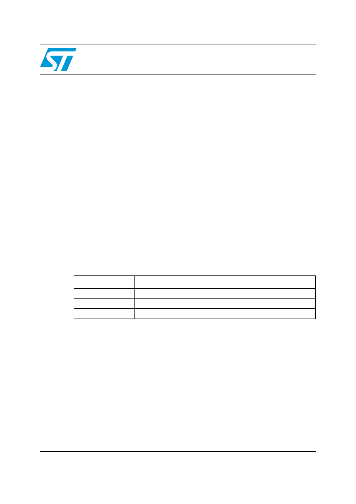
1 RC acquisition principle
The RC acquisition method is used to detect the human touch of any capacitive touch
sensor (key, wheel or slider) by measuring the small variation of the touch electrode
capacitance (C).
Electrode capacitance C is periodically charged and discharged through a fixed resistor (R).
The capacitance value depends on the following parameters: electrode area (A), relative
dielectric constant of the insulator (ε
between the two electrodes (d). The capacitance value is summarized with the formula:
Equation 1
Figure 1. Voltage applied on an RC network
), the relative permittivity of air (ε0) and the distance
R
A fixed voltage is applied on V
. The V
IN
voltage increases or decreases proportionally to
OUT
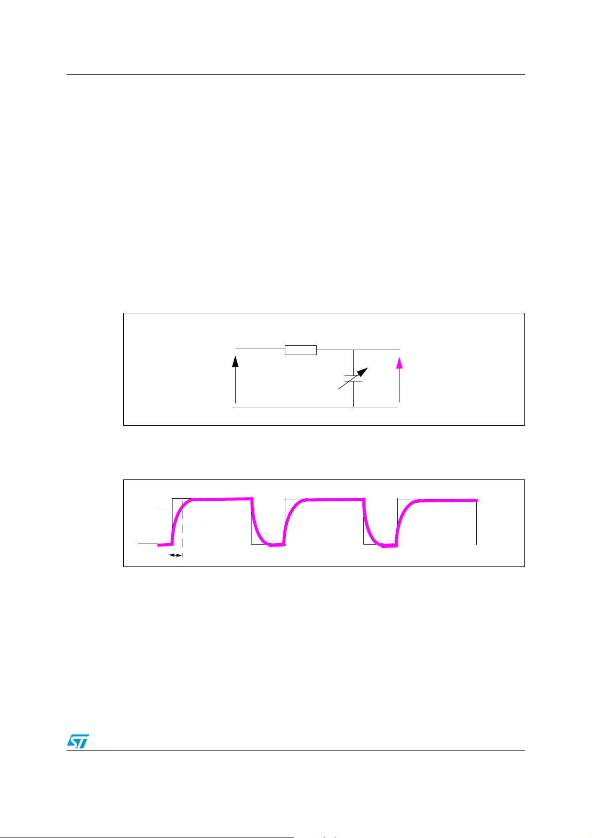
the capacitance value as shown in Figure 2.
Figure 2. Measuring the charge time
The capacitance value (C) is calculated by measuring the charge time (t
requires to reach the threshold V
TH
.
) the V
C
OUT
voltage
In touch sensing applications, the capacitance value (C) is the addition of a fixed
capacitance (electrode capacitance, C
(touch capacitance, C
) when it touches or is close to the electrode. The electrode
T
) and the capacitance added by the human finger
X
capacitance must be kept as low as possible to ensure touch detection which is only a
variation of a few picofarads (typically 5pF).
Using this acquisition principle, it is possible to determine if a finger is “touching” the
electrode or not.
3/12
Page 4
RC acquisition principle AN2927
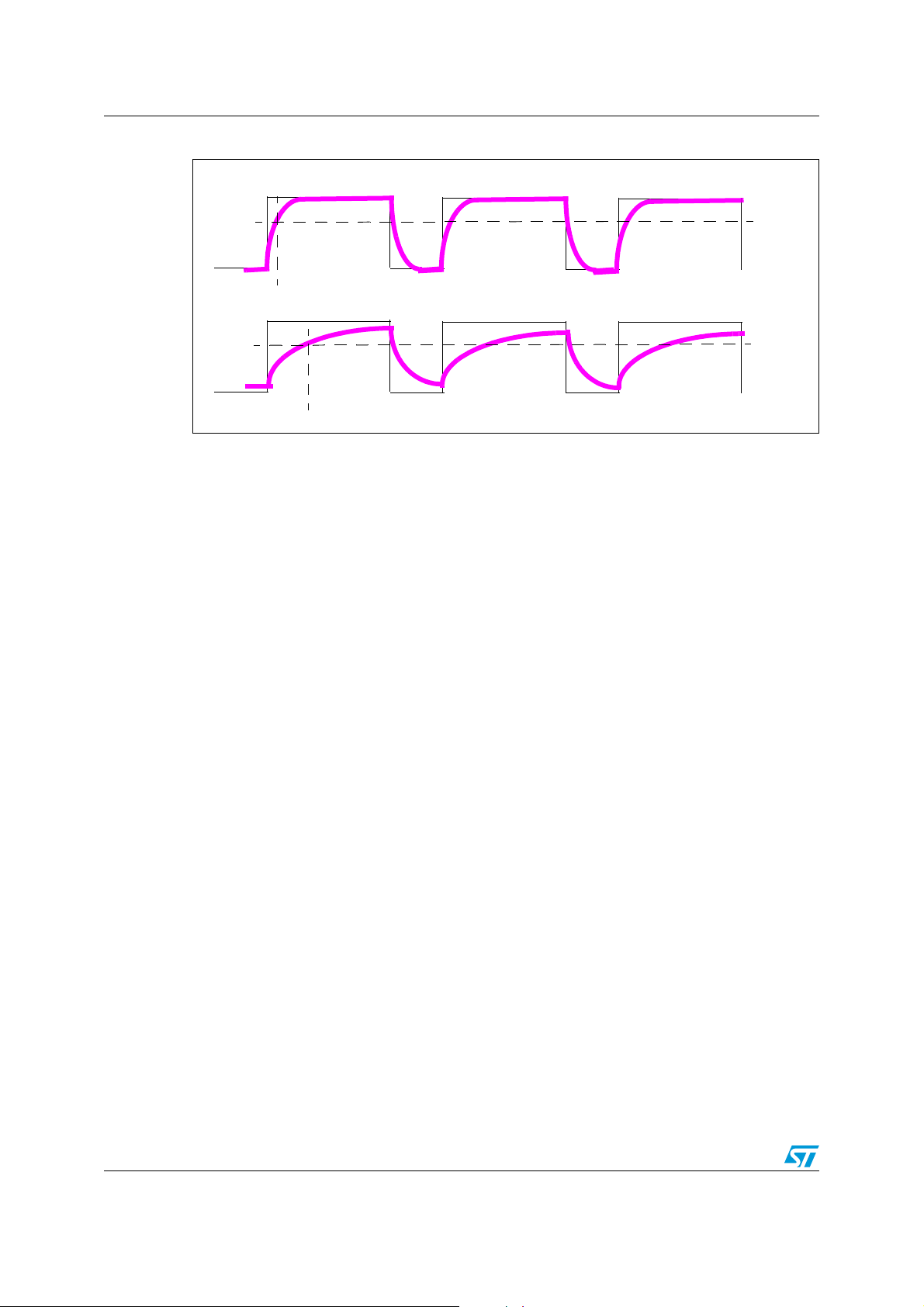
V
IN
V
OUT
t1
No touch
V
IN
V
OUT
t2
Human touch: the overall capacitance increases (t2 > t1)
Figure 3. Touch acquisition
This is the basic principle used in the acquisition layer of the touch sensing library to detect
a human touch.
4/12
Page 5

AN2927 Hardware implementation
MCU
GPIO
“Load I/O”
Electrode #1
R2
R1
CX (constant)
GPIO
“Acq I/O”
Electrode #2
Electrode #n
GPIO
GPIO
CT (variable)
Finger
C
X
(constant)
C
X
(constant)
2 Hardware implementation
Figure 4 illustrates an implementation example. The capacitive human touch is detected by
measuring the charge/discharge of the RC network composed of R1, R2 and electrode
capacitance (C
There is only one “Load I/O” pin for all the electrodes. Resistors R1 and R2 must be placed
as close as possible to the MCU. Resistor R1 (between hundreds Ohms to a few MOhms) is
the main resistor used to adjust the electrode sensitivity to touch. Resistor R2 (10kΩ) is
optional and is used to reduce noise sensitivity.
Figure 4. Capacitive touch sensing example implementation
) in parallel with the finger capacitance (CT) (approximately 5pF).
X
For more information please read Application Note AN2869 Guidelines for designing touch
sensing applications.
5/12
Page 6

Firmware implementation AN2927
Counter = start_value
Counter = stop_value
V
TH
3 Firmware implementation
This section describes the implementation of the RC acquisition principle in the ST touch
sensing firmware library.
3.1 Charge Time measurement principle
The charge time measurement must be accurate enough to ensure a robust capacitive
sensing application. There are two common ways to measure the charge time:
1. The first solution is using an input capture (IC) timer which is triggered when the
voltage reaches the threshold level. This approach offers a time measurement
resolution which is directly linked to the timer counter frequency. However, as one input
capture channel is required per electrode, standard MCUs are not compatible with this
type of capacitive sensing application.
2. The second solution uses both a simple timer (without IC capability) and a simple
software sequence which regularly checks if the voltage on the acquisition I/O has
reached the threshold level. In this case, the time resolution measurement is equal to
the number of CPU cycles used to execute a complete loop of the software sequence.
This measurement approach introduces some jitter which is not compatible with the
capacitive sensing acquisition. However, a large number of electrodes can be
implemented as there are no hardware constraints.
A variant of the second solution obtains a fixed measurement resolution equal to the CPU
frequency (f
ST touch sensing firmware library and is described below.
) by using an adaptive software sequence. This is the approach used in the
CPU
3.1.1 Basic measurement
A general purpose timer performs the charge time measurement. The timer counter start
value is saved (or reset) at the beginning of the capacitance charge. When the voltage on
the acquisition I/O (Acq I/O) reaches a certain threshold level (V
counter value is saved. The difference of the two time counter values gives the charge or
discharge time.
Figure 5. Timer counter values
), the current timer
TH
6/12
Page 7

AN2927 Firmware implementation
VIH crossing
V
IH
Detected here
CPU frequency
Sampling point
for eight
successive
measurements
Eight successive measurements are
delayed to sweep the crossing point area
t
V
IL
V
IH
V
DD
“Acq I/O” pin
“Load I/O” pin
1
2
3 4 5
1
GND
3.1.2 Oversampling
The purpose of oversampling is to provide a final measurement of the input voltage high and
low levels (V
Each successive V
span all the possible values.
The number of measurements necessary to span all the values are MCU core dependant.
For STM8 microcontrollers, this number is equal to 8.
Figure 6 illustrates this concept on an STM8 microcontroller
Figure 6. Input voltage measurements
and VIL) with the precision of the CPU clock.
IH
or VIL measurement is delayed by one CPU clock cycle in order to
IH
3.2 Input voltage measurement principle
In order to improve the robustness against voltage and temperature variations, two
measurements are performed consecutively on the electrodes: the first one measures the
capacitance charge until the V
discharge until the V
IL
detail on the acquisition electrode (Acq I/O) and on the Load I/O pin.
Figure 7. Capacitance charge/discharge measurements
level is reached. The second measures the capacitance
IH
level is reached. Figure 7 and table below illustrate what happens in
7/12
Page 8

Firmware implementation AN2927
t
V
IL
V
IH
V
DD
“Acq I/O” pin
“touched effect”
t2’t2t1’t1
Table 2. Capacitance charge/discharge measurement steps
Step Description
1. Load I/O pin is set in Output mode at V
1
2. Acq I/O pin is set in Output mode at VDD.
3. Timer counter V
Acq I/O pin is set in Input mode Hi-Z.
2
--> The electrode capacitance C
After the voltage on the Acq I/O pin reaches V
1. Timer counter V
3
calculated and saved (vih_stop – vih_start).
2. Acq I/O pin is set in Output mode at V
3. Load I/O pin is set in Output mode at GND.
4. Timer counter V
Acq I/O pin is set in Input mode Hi-Z.
4
--> The electrode capacitance C
After the voltage on the Acq I/O pin reaches V
1. Timer counter V
5
calculated and saved (vil_stop – vil_start).
2. The two measurements “vih_meas” and “vil_meas” are added and saved.
3. The process continues with Step 1.
3.3 Touched effect
.
DD
start value is saved (vih_start).
IH
is charging.
X
:
IH
stop value is saved (vih_stop) and the VIH measurement is
IH
.
DD
start value is saved (vil_start).
IL
is discharging.
X
:
IL
stop value is saved (vil_stop) and the VIL measurement is
IL
The electrode shape and size, the layout from the touch controller device to the electrode
(and more specifically the ground coupling) as well as the dielectric panel material and
thickness are the main parameters that define the value of the electrode capacitance (C
X
As a consequence, the RC charge and discharge values are directly dependant on this C
value. Figure 8 illustrates this “touched effect”.
The time <t1’> (where the V
same for the V
level with times t2’ and t2.
IL
level is reached) is greater than the time <t1>. This is the
IH
Figure 8. “Touched effect” example
).
X
8/12
Page 9

AN2927 Firmware implementation
t
“Touched effect”
Fixed number of VIH/VIL measurements
Configurable acquisition number (N)
Fixed (“burst group”)
Start electrode acquisition
Acquisition OK
BG1
Pass
BG3
Pass
BG2
Pass
BG4
Pass
3.4 Multi-acquisitions and HF noise rejection
To improve the measurement accuracy and reject high frequency (HF) noise, it is necessary
to perform these V
effectively “touched”. This number of acquisitions is calculated using one of two variables:
the first one is fixed and dependent on the MCU core and the other one is configurable
(through the configuration file of the TS library).
and VIL measurements several times before determining that the key is
IH
For information, the number of fixed acquisitions is set to ‘8’ for STM8 devices (8 V
measurements + 8 V
measurements).
IL
IH
Figure 9. Types of acquisitions
Note: The configurable acquisition number (N) can be set differently in the configuration file of the
TS Library for the single-channel keys and for the multi-channel keys.
The figures below illustrate examples of HF noise rejection. If the acquisition number (N) is
set to 4, a complete acquisition of one electrode will consist of 4 correct “burst groups”
(BGs). The word “correct” means that all measurements inside the group remain between a
minimum and a maximum limit.
These example show different scenarios depending on the level of noise. The green line
means that the V
V
measurement.
IH/VIL
measurement is correct, and the red line indicates an incorrect
IH/VIL
Figure 10 shows an example where there is no noise and no measurements are rejected.
In this example, all the measurements inside each burst group pass. The complete
acquisition is done quickly.
Figure 10. Example 1
9/12
Page 10

Firmware implementation AN2927
Acquisition OK
BG1
Pass
BG3
Fail
BG2
Pass
BG4
Pass
BG3
Fail
BG3
Pass
Remaining measurements
are skipped
r1
r2
Start
Acquisition stopped
BG1
Pass
BG2
Fail
BG2
Fail
BG3
Fail (max.)
BG2
Pass
BG3
Fail
Start
r1 r2 r3 r21
Figure 11 shows an example where there is a small amount of noise and some
measurements are rejected (i.e. r1 and r2).
In this example, the burst group 3 (BG3) is repeated until all measurements within this group
pass. More time is required for a complete acquisition.
Figure 11. Example 2
Figure 12 shows an example where there is a lot of noise and the maximum limit (i.e. 20) is
reached. In this case, the complete electrode acquisition is rejected.
In this example, the maximum number of rejected measurements is reached and the
acquisition is stopped on that electrode.
Figure 12. Example 3
Note: The maximum number of rejected measurements is set in the configuration file of the ST
touch sensing library.
Calculation of Min/Max limits
These two limits are calculated by applying a multiplication coefficient to the first VIH/VIL
measurement of each burst group. This multiplication factor is set inside the configuration
file of the ST touch sensing library. As a consequence the first V
each burst group is always “Pass”. In case the first measurement is “incorrect”, and the
consecutive ones are “correct”, the burst group will still be determined “Fail”.
measurements of
IH/VIL
10/12
Page 11

AN2927 Revision history
4 Revision history
Table 3. Document revision history
Date Revision Changes
30-Jan-2009 1 Initial release.
25-Mar-2009 2 Updated title and Figure 6: Input voltage measurements.
11/12
Page 12

AN2927
Please Read Carefully:
Information in this document is provided solely in connection with ST products. STMicroelectronics NV and its subsidiaries (“ST”) reserve the
right to make changes, corrections, modifications or improvements, to this document, and the products and services described herein at any
time, without notice.
All ST products are sold pursuant to ST’s terms and conditions of sale.
Purchasers are solely responsible for the choice, selection and use of the ST products and services described herein, and ST assumes no
liability whatsoever relating to the choice, selection or use of the ST products and services described herein.
No license, express or implied, by estoppel or otherwise, to any intellectual property rights is granted under this document. If any part of this
document refers to any third party products or services it shall not be deemed a license grant by ST for the use of such third party products
or services, or any intellectual property contained therein or considered as a warranty covering the use in any manner whatsoever of such
third party products or services or any intellectual property contained therein.
UNLESS OTHERWISE SET FORTH IN ST’S TERMS AND CONDITIONS OF SALE ST DISCLAIMS ANY EXPRESS OR IMPLIED
WARRANTY WITH RESPECT TO THE USE AND/OR SALE OF ST PRODUCTS INCLUDING WITHOUT LIMITATION IMPLIED
WARRANTIES OF MERCHANTABILITY, FITNESS FOR A PARTICULAR PURPOSE (AND THEIR EQUIVALENTS UNDER THE LAWS
OF ANY JURISDICTION), OR INFRINGEMENT OF ANY PATENT, COPYRIGHT OR OTHER INTELLECTUAL PROPERTY RIGHT.
UNLESS EXPRESSLY APPROVED IN WRITING BY AN AUTHORIZED ST REPRESENTATIVE, ST PRODUCTS ARE NOT
RECOMMENDED, AUTHORIZED OR WARRANTED FOR USE IN MILITARY, AIR CRAFT, SPACE, LIFE SAVING, OR LIFE SUSTAINING
APPLICATIONS, NOR IN PRODUCTS OR SYSTEMS WHERE FAILURE OR MALFUNCTION MAY RESULT IN PERSONAL INJURY,
DEATH, OR SEVERE PROPERTY OR ENVIRONMENTAL DAMAGE. ST PRODUCTS WHICH ARE NOT SPECIFIED AS "AUTOMOTIVE
GRADE" MAY ONLY BE USED IN AUTOMOTIVE APPLICATIONS AT USER’S OWN RISK.
Resale of ST products with provisions different from the statements and/or technical features set forth in this document shall immediately void
any warranty granted by ST for the ST product or service described herein and shall not create or extend in any manner whatsoever, any
liability of ST.
ST and the ST logo are trademarks or registered trademarks of ST in various countries.
Information in this document supersedes and replaces all information previously supplied.
The ST logo is a registered trademark of STMicroelectronics. All other names are the property of their respective owners.
© 2009 STMicroelectronics - All rights reserved
STMicroelectronics group of companies
Australia - Belgium - Brazil - Canada - China - Czech Republic - Finland - France - Germany - Hong Kong - India - Israel - Italy - Japan -
Malaysia - Malta - Morocco - Singapore - Spain - Sweden - Switzerland - United Kingdom - United States of America
www.st.com
12/12
 Loading...