

Page 1

AN2843
Application note
STEVAL-IHI002V1, capacitive touch-sensing
keyboard based on the STMPE1208S
Introduction
The STEVAL-IHI002V1 is a demonstration board designed to modernize, or even fully
replace, a conventional mechanical keyboard.
The demonstration board is based on the STMPE1208S 12-bit GPIO expander with an
additional 12-channel capacitive sensor, which is capable of interfacing a main MCU
through an I²C bus. The demonstration board is designed to work as a daughterboard for
the STEVAL-IHI001V1 demonstration board (washing machine user interface).
Once connected, the STEVAL-IHI002V1 will be automatically detected by the motherboard,
replacing the mechanical keys with a wheel, a slider and 5 buttons.
November 2009 Doc ID 15112 Rev 2 1/9
www.st.com
Page 2

Contents AN2843
Contents
1 STMPE1208S: 12-channel capacitive touchkey controller . . . . . . . . . . 3
2 Application schematic . . . . . . . . . . . . . . . . . . . . . . . . . . . . . . . . . . . . . . . 4
3 Bill of material . . . . . . . . . . . . . . . . . . . . . . . . . . . . . . . . . . . . . . . . . . . . . . 5
4 STEVAL-IHI002V1 demonstration board photos . . . . . . . . . . . . . . . . . . 6
5 Revision history . . . . . . . . . . . . . . . . . . . . . . . . . . . . . . . . . . . . . . . . . . . . 8
2/9 Doc ID 15112 Rev 2
Page 3
AN2843 STMPE1208S: 12-channel capacitive touchkey controller
1 STMPE1208S: 12-channel capacitive touchkey
controller
The STMPE1208S is a 12-bit GPIO device with additional 12-channel capacitive sensors,
which is capable of interfacing a main MCU through an I²C bus.
The sensors in the device detect finger contact through the additional capacitance
introduced to the sensor, providing fast and accurate results at very low power consumption.
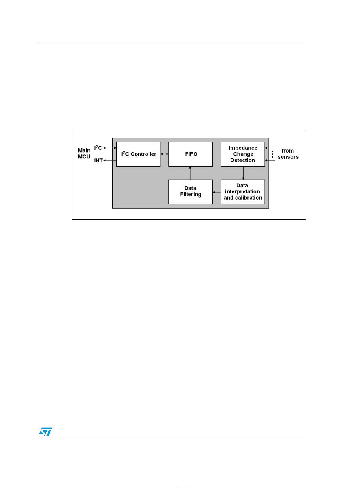
Figure 1. STMPE1208S block diagram
!-V
When a sensor is touched, the increase in capacitance causes a delay in the clock signal on
the relevant sensing pin. The signal is then compared with a reference clock. The difference
is a direct representation of the additional capacitance introduced by the finger touch.
Environment factors, such as temperature and humidity, can affect the measured
capacitance value. The calibration unit ensures consistent key sensitivity, even in the
presence of significant shifts in temperature, humidity, device lot and PCB characteristics.
The output from the calibration unit provides an instantaneous touch/no-touch status. This
signal is sent to the data filtering stage, which is made up of an integration unit, a filter unit
and a noise filtering unit.
The sensors can be affected by high-frequency noise if working near highly emissive circuits
such as a DC-DC converters or PWM controllers. The noise filtering helps the device
distinguish between a real touch or an emission-related false touch.
The STMPE1208S communicates with a main MCU through an I²C bus interface. It is
configured as a slave device, and supports both standard mode (up to 100 Kbps) and fast
mode (up to 400 Kbps), as well as 7-bit and 10-bit addressing modes.
The device can manage 2 types of interrupt events: a general interrupt related to the GPIO
ports, and a touch interrupt which occurs when touching a sensor.
Doc ID 15112 Rev 2 3/9
Page 4

Application schematic AN2843
2 Application schematic
The STEVAL-IHI002V1 is a daughterboard intended to be connected to the STEVALIHI001V1 demonstration board (please refer to user manual UM0557 for further
information). The +5 VDC (VDD) power supply is provided by the STEVAL-IHI001V1
demonstration board through connectors J1 and J2. The STMPE1208S needs only a few
capacitors to run properly: a decoupling capacitor (C1), a reference capacitor (C2), and a
capacitor to stabilize the internal voltage regulator (C3).
The reset pin is pulled up by a resistor and is directly controlled by the main MCU. The
STMPE1208S communicates with the main MCU via an I²C bus. ID_0 and ID_1 set the
device address. Interrupt events GINT and TINT are sent to the main MCU as well. The
slider is designed using 3 capacitive sensing pins (S-T0, S-T1, S-T2). The wheel is also
implemented using 3 capacitive sensing pins (S-T8, S-T9, S-T10). Each button is connected
to a single capacitive sensing pin, from S-T3 to S-T7, for a total of 5 buttons. The graphic
design of the slider, the wheel, and the 5 buttons is generated directly on the PCB surface
through modeling of the copper area. The corrective capacitors C5-C16 are optional. Their
values are in the range of very few pF. They are necessary in cases where the PCB routes
between the capacitive sensing keys and the STMPE1208S are too long and vary
significantly from one to the other. Such corrective capacitors have not been mounted in the
STEVAL-IHI002V1. The GPIO ports are set as outputs and connected to 12 LEDs through a
series resistor. Each LED is an image of the respective capacitive sensing pin. This means
the LED will turn-on as soon as a touch is detected. The demonstration board is equipped
with connector J3 to allow an external board other than the STEVAL-IHI001V1 to be
connected to the STMPE1208S via I²C bus.
Figure 2. Application schematic
+VDD
I2CD
I2CC
RST0
MD1 MD2
MD1
MD2
GINT
TIN T
PA2
PA3
PA4
RST0
+VDD
I2CD
I2CC
DL1
DL2
DL3
DL4
DL5
DL6
DL7
DL8
DL9
DL10
DL11
DL12
J3
CON10A
)#%XPANDER
J1
CON12
1
2
3
4
5
6
7
8
9
10
11
12
12
34
56
78
910
R1 510
R2 510
R3 510
R4 510
R5 510
R6 510
R7 510
R8 510
R9 510
R10 510
R11 510
R12 510
+VDD
TP2
LED0
LED1
LED2
LED3
LED4
LED5
LED6
LED7
LED8
LED9
LED10
LED11
LED0
LED1
LED2
LED3
LED4
LED5
LED6
LED7
LED8
LED9
LED10
LED11
I2CD
I2CC
GINT
TIN T
J2
CON10
1
2
3
4
5
6
7
8
9
10
U1
STMPE1208S
2
1
40
39
38
37
14
13
12
11
10
9
3
4
6
5
7
36
35
8
S-T3
S-T4
S-T5
S-T6
S-T7
GPIO_0
GPIO_1
GPIO_2
GPIO_3
GPIO_4
GPIO_5
GPIO_6
GPIO_7
GPIO_8
GPIO_9
GPIO_10
GPIO_11
SDATA
SCLK
GINT
TIN T
BEEP
ID_0
ID_1
TCLK
C5 1pF
S-T0
S_IN_0
S_IN_1
S_IN_2
S_IN_3
S_IN_4
S_IN_5
S_IN_6
S_IN_7
S_IN_8
S_IN_9
S_IN_10
S_IN_11
RESET
VREG
S_REF
P1
PAD
1
P2
PAD
1
P3
PAD
1
P4
PAD
1
P5
PAD
1
S-T9
S-T8
S-T10
S-T2
S-T1
S-T0
1
2
3
1
2
3
W1
WHEEL
S1
SLIDE
GND
GND
S-T1
32
S-T2
31
S-T3
30
S-T4
29
S-T5
28
S-T6
23
S-T7
22
S-T8
21
S-T9
20
S-T10
19
S-T11
18
27
VPH
15
VPH
RST0
34
26
25
V25
17
C2
4.7pF
24
16
R13 10K
C3
4.7uF
C1
100nF
+VDD
TP1
S-T0
33
S-T1
S-T2
S-T3
S-T4
S-T5
S-T6
S-T7
S-T8
S-T9
S-T10
S-T11
/PTIONAL
CAPACITORS
C6 1pF
C7 1pF
C8 1pF
C9 1pF
C10 1pF
C11 1pF
C12 1pF
C13 1pF
C14 1pF
C15 1pF
C16 1pF
!-V
4/9 Doc ID 15112 Rev 2
Page 5
AN2843 Bill of material
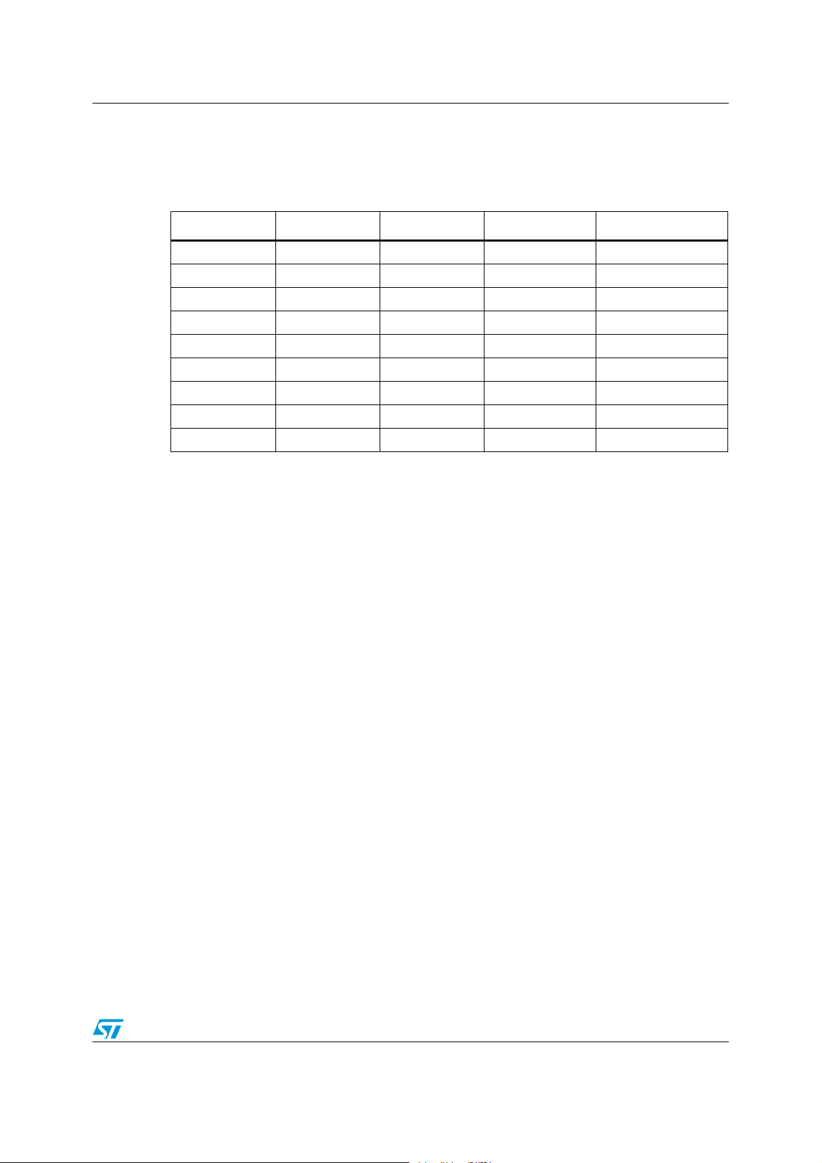
3 Bill of material
Table 1. Bill of material
Item Quantity Reference Part number Manufacturer
1 1 C1 100 nF 0805 SMD
2 1 C2 4.7 pF 0805 SMD
3 1 C3 4.7 µF 10 V SMD
4 12 DL1-DL12 LED 1206 - green
5 1 J1 PIN strip 12x
6 1 J2 PIN strip 10x
7 12 R1-R12 510 W 0805 SMD
8 1 R13 10 kW 0805 SMD
9 1 U1 STMPE1208S STMicroelectronics
Doc ID 15112 Rev 2 5/9
Page 6

STEVAL-IHI002V1 demonstration board photos AN2843
4 STEVAL-IHI002V1 demonstration board photos
Figure 3. Top view
AM01727v1
Figure 4. Bottom view
Figure 5. STEVAL-IHI002V1 connected to the STEVAL-IHI001V1
6/9 Doc ID 15112 Rev 2
AM01728v1
AM01729v1
Page 7

AN2843 STEVAL-IHI002V1 demonstration board photos
Figure 6. Angle view
AM01730v1
Doc ID 15112 Rev 2 7/9
Page 8

Revision history AN2843
5 Revision history
Table 2. Document revision history
Date Revision Changes
21-Jan-2009 1 Initial release
09-Nov-2009 2
Changed the title of Section 1 to “STMPE1208S: 12-channel
capacitive touchkey controller”
8/9 Doc ID 15112 Rev 2
Page 9

AN2843
Please Read Carefully:
Information in this document is provided solely in connection with ST products. STMicroelectronics NV and its subsidiaries (“ST”) reserve the
right to make changes, corrections, modifications or improvements, to this document, and the products and services described herein at any
time, without notice.
All ST products are sold pursuant to ST’s terms and conditions of sale.
Purchasers are solely responsible for the choice, selection and use of the ST products and services described herein, and ST assumes no
liability whatsoever relating to the choice, selection or use of the ST products and services described herein.
No license, express or implied, by estoppel or otherwise, to any intellectual property rights is granted under this document. If any part of this
document refers to any third party products or services it shall not be deemed a license grant by ST for the use of such third party products
or services, or any intellectual property contained therein or considered as a warranty covering the use in any manner whatsoever of such
third party products or services or any intellectual property contained therein.
UNLESS OTHERWISE SET FORTH IN ST’S TERMS AND CONDITIONS OF SALE ST DISCLAIMS ANY EXPRESS OR IMPLIED
WARRANTY WITH RESPECT TO THE USE AND/OR SALE OF ST PRODUCTS INCLUDING WITHOUT LIMITATION IMPLIED
WARRANTIES OF MERCHANTABILITY, FITNESS FOR A PARTICULAR PURPOSE (AND THEIR EQUIVALENTS UNDER THE LAWS
OF ANY JURISDICTION), OR INFRINGEMENT OF ANY PATENT, COPYRIGHT OR OTHER INTELLECTUAL PROPERTY RIGHT.
UNLESS EXPRESSLY APPROVED IN WRITING BY AN AUTHORIZED ST REPRESENTATIVE, ST PRODUCTS ARE NOT
RECOMMENDED, AUTHORIZED OR WARRANTED FOR USE IN MILITARY, AIR CRAFT, SPACE, LIFE SAVING, OR LIFE SUSTAINING
APPLICATIONS, NOR IN PRODUCTS OR SYSTEMS WHERE FAILURE OR MALFUNCTION MAY RESULT IN PERSONAL INJURY,
DEATH, OR SEVERE PROPERTY OR ENVIRONMENTAL DAMAGE. ST PRODUCTS WHICH ARE NOT SPECIFIED AS "AUTOMOTIVE
GRADE" MAY ONLY BE USED IN AUTOMOTIVE APPLICATIONS AT USER’S OWN RISK.
Resale of ST products with provisions different from the statements and/or technical features set forth in this document shall immediately void
any warranty granted by ST for the ST product or service described herein and shall not create or extend in any manner whatsoever, any
liability of ST.
ST and the ST logo are trademarks or registered trademarks of ST in various countries.
Information in this document supersedes and replaces all information previously supplied.
The ST logo is a registered trademark of STMicroelectronics. All other names are the property of their respective owners.
© 2009 STMicroelectronics - All rights reserved
STMicroelectronics group of companies
Australia - Belgium - Brazil - Canada - China - Czech Republic - Finland - France - Germany - Hong Kong - India - Israel - Italy - Japan -
Malaysia - Malta - Morocco - Philippines - Singapore - Spain - Sweden - Switzerland - United Kingdom - United States of America
www.st.com
Doc ID 15112 Rev 2 9/9
 Loading...