


AN2825
Application Note
S-Touch
STMPE811 resistive touchscreen controller advanced features
Introduction
This application note provides details on the advanced features of the S-Touch® STMPE811
touchscreen controllers.
In particular, the STMPE811 device is a GPIO (general purpose input/output) port expander
equipped with an advanced touchscreen controller which helps to reduce the load of the
host and simplify data processing.
The document is divided into three sections which respectively describe: touchscreen
advanced features, available touchscreen controller settings and basic guidelines on the use
of interrupts.
®
September 2011 Doc ID 15023 Rev 1 1/11
www.st.com

Contents AN2825
Contents
1 STMPE811 advanced features . . . . . . . . . . . . . . . . . . . . . . . . . . . . . . . . . 3
1.1 Autonomous operation . . . . . . . . . . . . . . . . . . . . . . . . . . . . . . . . . . . . . . . . 3
1.2 FIFO memory . . . . . . . . . . . . . . . . . . . . . . . . . . . . . . . . . . . . . . . . . . . . . . . 3
1.3 Movement tracking . . . . . . . . . . . . . . . . . . . . . . . . . . . . . . . . . . . . . . . . . . . 4
1.4 Averaging data to optimize noise cancellation . . . . . . . . . . . . . . . . . . . . . . 5
1.5 Window tracking . . . . . . . . . . . . . . . . . . . . . . . . . . . . . . . . . . . . . . . . . . . . . 6
2 Settings description . . . . . . . . . . . . . . . . . . . . . . . . . . . . . . . . . . . . . . . . . 7
2.1 ADC sample time . . . . . . . . . . . . . . . . . . . . . . . . . . . . . . . . . . . . . . . . . . . . 7
2.2 ADC bit mode . . . . . . . . . . . . . . . . . . . . . . . . . . . . . . . . . . . . . . . . . . . . . . . 7
2.3 ADC clock frequency . . . . . . . . . . . . . . . . . . . . . . . . . . . . . . . . . . . . . . . . . 7
2.4 TSC operating mode . . . . . . . . . . . . . . . . . . . . . . . . . . . . . . . . . . . . . . . . . 7
2.5 Tracking index . . . . . . . . . . . . . . . . . . . . . . . . . . . . . . . . . . . . . . . . . . . . . . . 7
2.6 Averaging . . . . . . . . . . . . . . . . . . . . . . . . . . . . . . . . . . . . . . . . . . . . . . . . . . 7
2.7 Touch detect delay . . . . . . . . . . . . . . . . . . . . . . . . . . . . . . . . . . . . . . . . . . . 8
2.8 Driver settling time delay . . . . . . . . . . . . . . . . . . . . . . . . . . . . . . . . . . . . . . 8
3 Interrupt user guide . . . . . . . . . . . . . . . . . . . . . . . . . . . . . . . . . . . . . . . . . 9
3.1 Touch detect interrupt . . . . . . . . . . . . . . . . . . . . . . . . . . . . . . . . . . . . . . . . . 9
3.2 FIFO interrupt . . . . . . . . . . . . . . . . . . . . . . . . . . . . . . . . . . . . . . . . . . . . . . . 9
4 Revision history . . . . . . . . . . . . . . . . . . . . . . . . . . . . . . . . . . . . . . . . . . . 10
2/11 Doc ID 15023 Rev 1
AN2825 STMPE811 advanced features
1 STMPE811 advanced features
The touchscreen advanced features such as autonomous operation, movement tracking
algorithm to avoid excessive data, a 128-depth FIFO buffer and a programmable active
window feature that may be used in applications without increasing the host load.
1.1 Autonomous operation
The STMPE811 device is integrated with a hard-wired touchscreen controller, for a 4-wire
resistive type touchscreen, able to operate in an autonomous way, and interrupts the
connected CPU only when a pre-defined event occurs.
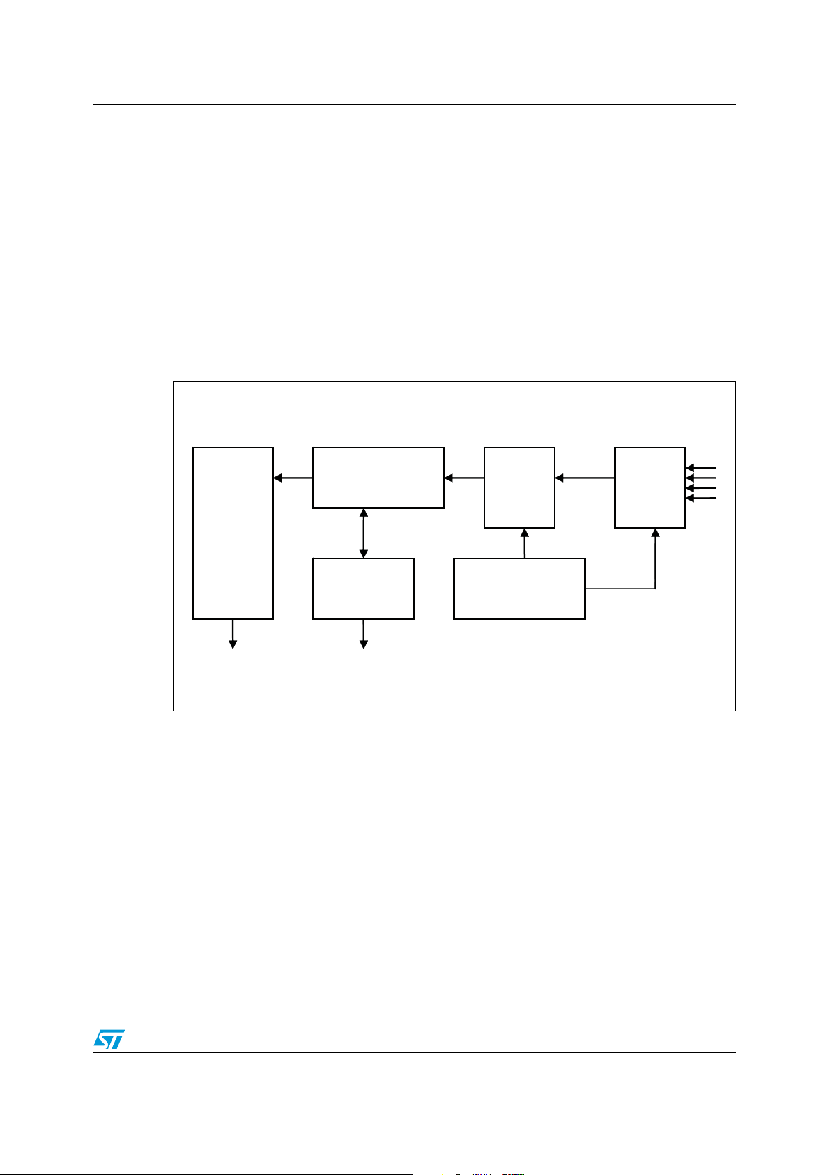
Figure 1. Touchscreen controller block diagram
FIFO
The STMPE811 touchscreen controller converts the ADC output into digital location data
(coordinates) and stores these in a FIFO for system access. This FIFO can be accessed
directly by the system as and when needed. This design reduces the system loading and
2
the I
C bus utilization.
1.2 FIFO memory
The FIFO memory has a depth of 128 sectors, enough for 128 sets of touch data at
maximum resolution (2 x 12 bits). The FIFO can be programmed to generate an interrupt
when it is filled to a pre-determined level.
Movement
and
window tracking
FIFO
and
interrupt control
10/12 bit
ADC
Driver
and
switch control
Switch
and
drivers
AM00745V1
The devices convert the data automatically when a touch is detected. The data is stored in
the FIFO memory for the host to read.
The FIFO memory is equipped with a control and status register where the host may refer to
it during its operation.
Doc ID 15023 Rev 1 3/11
STMPE811 advanced features AN2825
Below is a list of the various status of the FIFO memory reported in the control and status
registers (FIFO__CTRL_STA register, address 0x4B):
● FIFO overflow:
reports ‘1’ when FIFO memory is full and new data is coming.
● FIFO full:
reports ‘1’ when FIFO memory is full.
● FIFO empty:
reports ‘1’ when there is no data in FIFO memory.
● FIFO threshold trigger:
reports ‘1’ when the number of data in FIFO memory exceeds the number specified by
user in FIFO_SIZE register.
In the same register there is 1 bit for the user to put FIFO memory in reset mode by writing 1
to this bit. The data in the FIFO will be flushed when FIFO is in reset mode.
The host needs to read the data in the FIFO memory consistently. For example, in XYZ
mode, a single data consists of 3 bytes where X, Y and Z data is included. Hence, each data
read transaction must consist of multiples of 3 bytes in length to avoid confusion and data
loss.
Please refer to the STMPE811 datasheet for a detailed description of each register.
1.3 Movement tracking
The movement tracking feature reduces the number of samples generated by the
STMPE811 device. Using this feature, the device will receive only data that satisfies the
criteria set by the host.
The system host may select one of the 8 tracking index options: 0, 4, 8, 16, 32, 64, 92 and
127. The value of movement index refers to the native resolution of the ADC, which is 4096
points for full range.
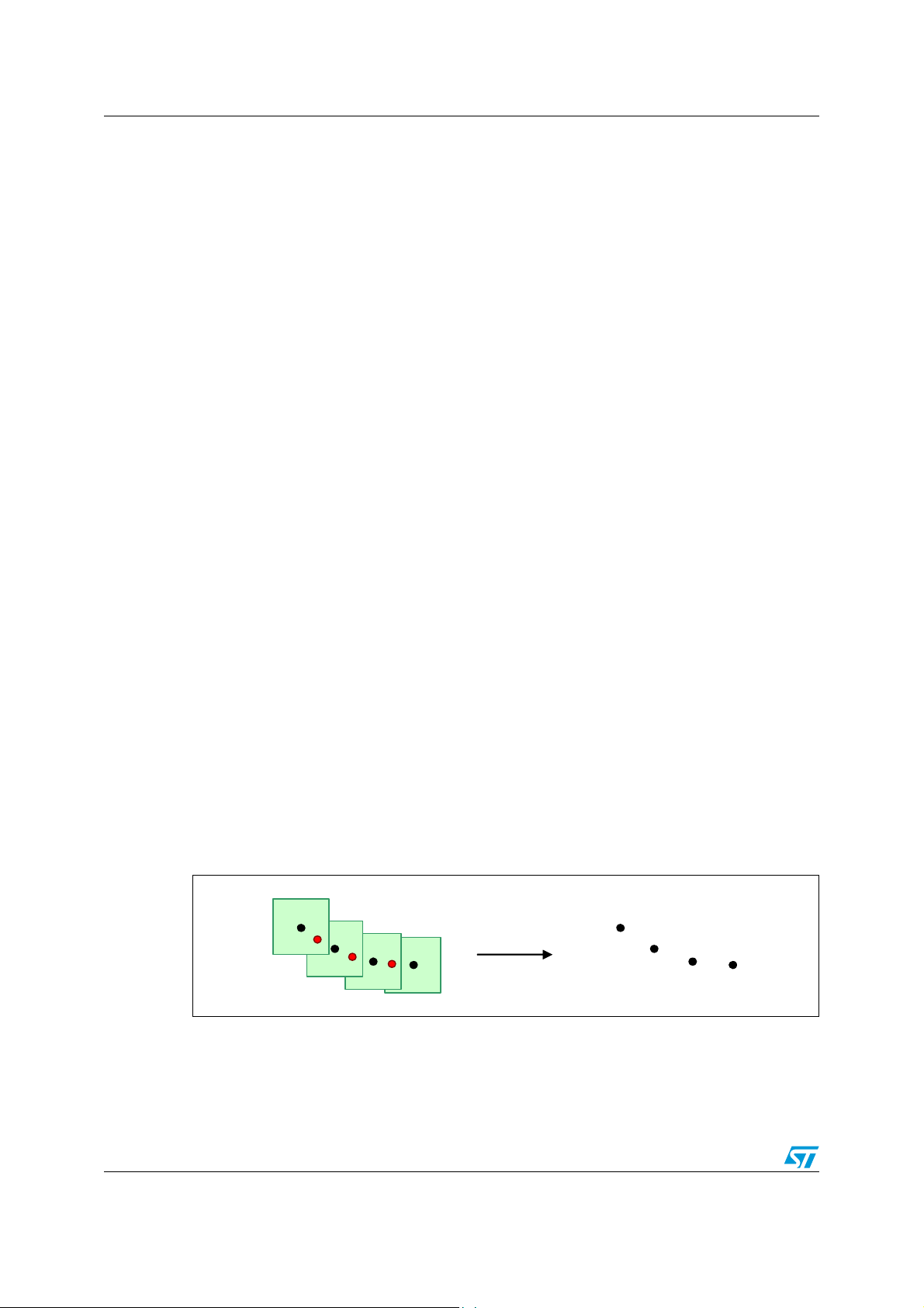
In XY mode, for example, the “127 points” option is selected, valid data form a square that is
127 points in size where the valid data being the center of the square. New data which is
inside this box is discarded (not stored in the FIFO memory). If new data is located outside
the square, the data is taken and used as the center of new square. This is illustrated in
Figure 2 which shows how the tracking index eliminates the data inside the tracking area
which is formed in the surrounding of valid data.
Figure 2. Tracking index
In XYZ mode, there is another factor that affects the tracking index function; the Z value. The
tracking index algorithm still considers new data inside the tracking area as valid data if the
Z value is lower than the previous valid data (pressure of new data is higher than previous
valid data).
4/11 Doc ID 15023 Rev 1

AN2825 STMPE811 advanced features
1.4 Averaging data to optimize noise cancellation
If the averaging feature is activated, the STMPE811 device samples more than 1 time to
produce a single data. The options for averaging are 1, 2, 4 and 8.
For example, if the “4 samples” averaging option is used, the device measures each X-, Yand Z- data 4 times and calculates the average before storing a data into the FIFO memory.
This feature helps to reduce the host load if the application requires averaging due to
random noise captured by the panel.
Doc ID 15023 Rev 1 5/11
STMPE811 advanced features AN2825
1.5 Window tracking
Window tracking is another interesting feature which allows the user to define an active area
including only the data that are considered to be valid. As a consequence, the data outside
the active area are discarded. The host only needs to write in the touchscreen controllers’
registers once to use this feature.
It must be ensured that the data written in the STMPE811 window tracking registers is in the
form of raw data (ADC data). Hence, the transfer function from raw data to display location
data needs to be used.
The transfer function from raw data to display coordinates is shown below:
Equation 1
YD0.5YR20–=
Where Y
= Y axis in display coordinates, and YR = raw data Y.
D
For example, if the user wants to set the Top Right Y as 1000 display’s Y axis, before writing
to the device’s register, the data needs to be transformed to an ADC scale using the transfer
function:
Equation 2
Y
2YD20+()=
R
Then the data may be written to the register.
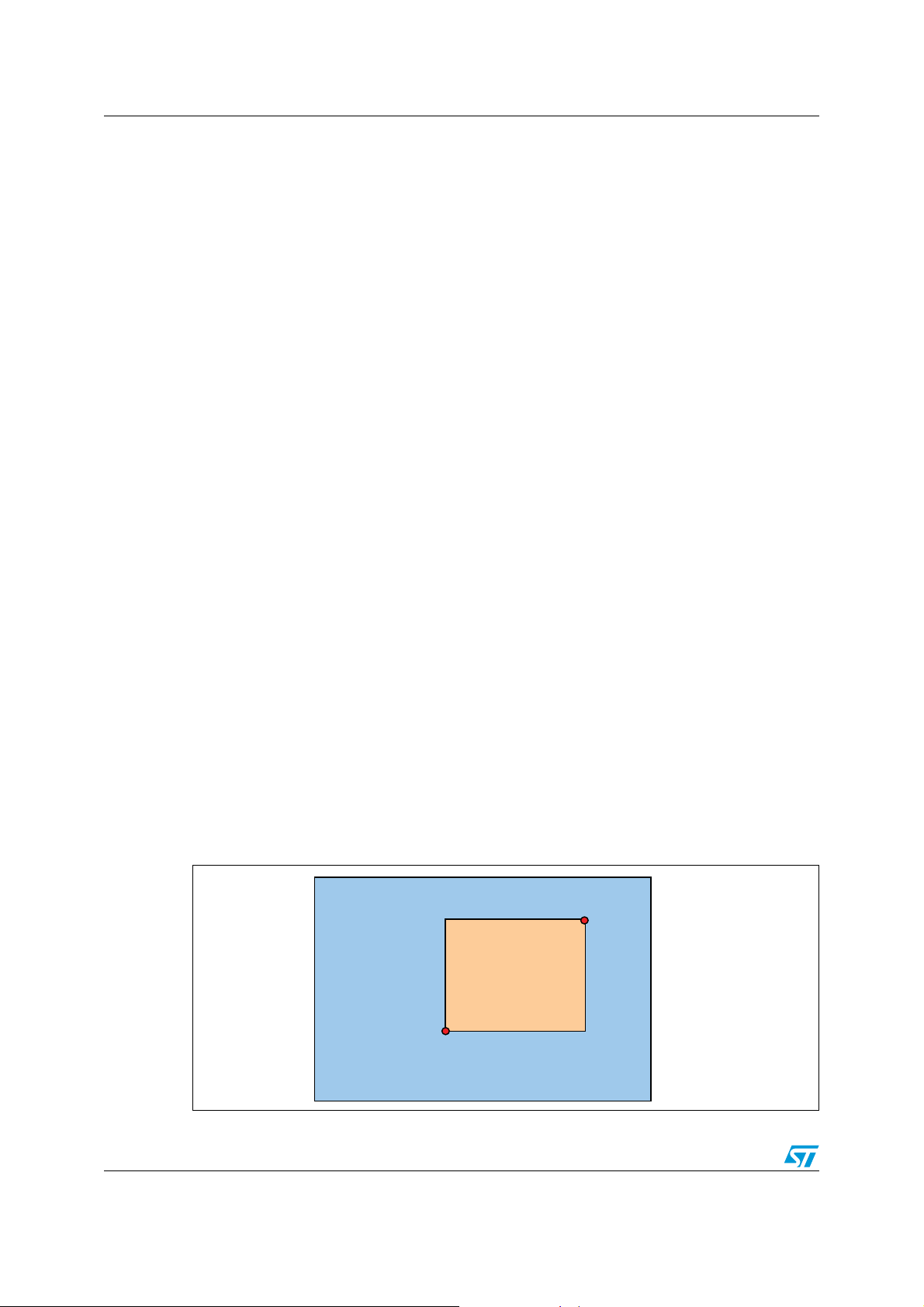
Two coordinates points need to be written to the STMPE811 registers: the top right and the
bottom left points. These two points form an active area where the data is considered valid
and stored in FIFO memory. The data outside the active area is discarded (Figure 3).
Figure 3. Active area definition
Display
Active area
Top Right
right (X,Y)
Bottom Left
left (X,Y)
6/11 Doc ID 15023 Rev 1

AN2825 Settings description
2 Settings description
In this section, the various settings available in the STMPE811 touchscreen controller are
described.
2.1 ADC sample time
The ADC sample time setting allows you to determine the time required by the ADC to
sample a single data in number of clock cycles. The shorter the time, the higher the
sampling rate that can be achieved but with less accuracy and vice-versa. The
recommended setting is 80 clock cycles as a compromise between speed and accuracy.
2.2 ADC bit mode
The ADC bit mode setting determines the ADC output resolution.
There are two options: 10 and 12 bits. The 10-bit ADC output is enough in most applications
using a small screen, such as 3.5” while for bigger screen applications, the 12-bit resolution
is recommended to achieve a sufficient touch resolution.
2.3 ADC clock frequency
The recommended setting for the ADC clock frequency is 3.25 MHz to get high a sampling
rate and at the same time accurate data. The accuracy of the measurement may be reduced
by selecting a higher clock speed.
2.4 TSC operating mode
Five options may be selected determining the type of output of the device’s conversion from
the touchscreen panel: XYZ, XY, X, Y and Z. Depending on the application, the user may
select different options.
2.5 Tracking index
The tracking index functionality has been explained in Section 1.5.
2.6 Averaging
The average setting has been explained in Section 1.4.
Doc ID 15023 Rev 1 7/11

Settings description AN2825
2.7 Touch detect delay
Touch detect delay is the delay time from the activation of the pull-up resistor in the X+ line
to the time the device performs the touch detection. In cases where a filter capacitor is
placed in the touchscreen lines, the pull-up resistor needs time to pull the X+ line high. This
implies that the user needs to choose enough “touch detect delay” for different values of the
filtering capacitor.
The STMPE811 touch detect pull-up resistor is 50 kΩ, hence the minimum touch detect
delay can be calculated by using the following formula:
Equation 3
t1.6094RCminarg+ 80470C m inarg+==
Where C is the value of the filtering capacitor.
It is good practice to allow around 50% as a margin for safety. If the touch detect delay is not
configured correctly, the device may senses false touches and prevent the device from
entering auto-sleep mode (more power consumption).
2.8 Driver settling time delay
The same rule described above applies to the conversion/measurement cycle when a touch
is detected.
The user needs to set enough settling time in order to get reliable accuracy. If a filtering
capacitor is placed, the settling time needs to be set longer. Otherwise, the device starts the
measurement when the signal is still in transient mode (not yet settled down), this may lead
to inaccuracy of the measurement.
As a general rule, 1-5 nF capacitors require around 500
around 1 ms. The exact value is recommended to be selected during prototype testing since
the capacitance of the touchscreen panel may vary.
µs settling time, and 5-10 nF need
8/11 Doc ID 15023 Rev 1

AN2825 Interrupt user guide
3 Interrupt user guide
The interrupt sources in the touchscreen controller are:
● Touch detect
● FIFO empty
● FIFO full
● FIFO overflow
● FIFO threshold.
3.1 Touch detect interrupt
A real-time touch detection can be monitored at bit 7 (TSC_STA) of the touchscreen control
register (TSC_CTRL). The transition of the status is latched at bit 1 (TOUCH_DET) of the
interrupt status register (INT_STA). For example, the transition from 0 to 1 in the TSC_STAbit of TSC_CTRL register will be captured as '1' in the TOUCH_DET-bit of the INT_STA
register. Similarly for transition from 1 to 0. Hence, both pen-down and pen-up events can
trigger interrupt signals. The TOUCH_DET-bit needs to be cleared after it is read, otherwise
the new status will not be latched.
3.2 FIFO interrupt
Similar to the touch detect, the real-time status of FIFO can be monitored from the
FIFO_CTRL_STA register. If any of the status becomes ‘1’, the value is latched to the
INT_STA register.
If the status in the interrupt status register is not cleared after it is read, the status is not
cleared automatically. This may be misleading for the user when reading the interrupt status
register (INT_STA) where FIFO_EMPTY and FIFO_FULL or FIFO_OVERFLOW may occur
simultaneously, since they are latched and in some operations it is not cleared.
It is recommended to read only the enabled bit status. For example, FIFO_THRESHOLD
and FIFO_OVERFLOW is enabled, when an interrupt is generated, the host needs only to
check these two bits, and clear them after doing all the necessary actions. The other bits
such as FIFO empty may be in ‘1’ state, but since it is not used, it can be ignored.
Doc ID 15023 Rev 1 9/11

Revision history AN2825
4 Revision history
Table 1. Document revision history
Date Revision Changes
13-Sep-2011 1 Initial release.
10/11 Doc ID 15023 Rev 1

AN2825
Please Read Carefully:
Information in this document is provided solely in connection with ST products. STMicroelectronics NV and its subsidiaries (“ST”) reserve the
right to make changes, corrections, modifications or improvements, to this document, and the products and services described herein at any
time, without notice.
All ST products are sold pursuant to ST’s terms and conditions of sale.
Purchasers are solely responsible for the choice, selection and use of the ST products and services described herein, and ST assumes no
liability whatsoever relating to the choice, selection or use of the ST products and services described herein.
No license, express or implied, by estoppel or otherwise, to any intellectual property rights is granted under this document. If any part of this
document refers to any third party products or services it shall not be deemed a license grant by ST for the use of such third party products
or services, or any intellectual property contained therein or considered as a warranty covering the use in any manner whatsoever of such
third party products or services or any intellectual property contained therein.
UNLESS OTHERWISE SET FORTH IN ST’S TERMS AND CONDITIONS OF SALE ST DISCLAIMS ANY EXPRESS OR IMPLIED
WARRANTY WITH RESPECT TO THE USE AND/OR SALE OF ST PRODUCTS INCLUDING WITHOUT LIMITATION IMPLIED
WARRANTIES OF MERCHANTABILITY, FITNESS FOR A PARTICULAR PURPOSE (AND THEIR EQUIVALENTS UNDER THE LAWS
OF ANY JURISDICTION), OR INFRINGEMENT OF ANY PATENT, COPYRIGHT OR OTHER INTELLECTUAL PROPERTY RIGHT.
UNLESS EXPRESSLY APPROVED IN WRITING BY TWO AUTHORIZED ST REPRESENTATIVES, ST PRODUCTS ARE NOT
RECOMMENDED, AUTHORIZED OR WARRANTED FOR USE IN MILITARY, AIR CRAFT, SPACE, LIFE SAVING, OR LIFE SUSTAINING
APPLICATIONS, NOR IN PRODUCTS OR SYSTEMS WHERE FAILURE OR MALFUNCTION MAY RESULT IN PERSONAL INJURY,
DEATH, OR SEVERE PROPERTY OR ENVIRONMENTAL DAMAGE. ST PRODUCTS WHICH ARE NOT SPECIFIED AS "AUTOMOTIVE
GRADE" MAY ONLY BE USED IN AUTOMOTIVE APPLICATIONS AT USER’S OWN RISK.
Resale of ST products with provisions different from the statements and/or technical features set forth in this document shall immediately void
any warranty granted by ST for the ST product or service described herein and shall not create or extend in any manner whatsoever, any
liability of ST.
ST and the ST logo are trademarks or registered trademarks of ST in various countries.
Information in this document supersedes and replaces all information previously supplied.
The ST logo is a registered trademark of STMicroelectronics. All other names are the property of their respective owners.
© 2011 STMicroelectronics - All rights reserved
STMicroelectronics group of companies
Australia - Belgium - Brazil - Canada - China - Czech Republic - Finland - France - Germany - Hong Kong - India - Israel - Italy - Japan -
Malaysia - Malta - Morocco - Philippines - Singapore - Spain - Sweden - Switzerland - United Kingdom - United States of America
www.st.com
Doc ID 15023 Rev 1 11/11
 Loading...