ST AN2813 APPLICATION NOTE

AN2813

Application note

TDE1708DFT in IO-Link applications

1 Introduction

This application note investigates the possibility of using a TDE1708DFT switch for the physical layer transmitter realization of 3-wire IO-Link sensors.

The TDE1708DFT is an integrated power switch especially dedicated to proximity detectors. It can deliver up to 250 mA, enables high-side and low-side configurations and includes

a number of protections.

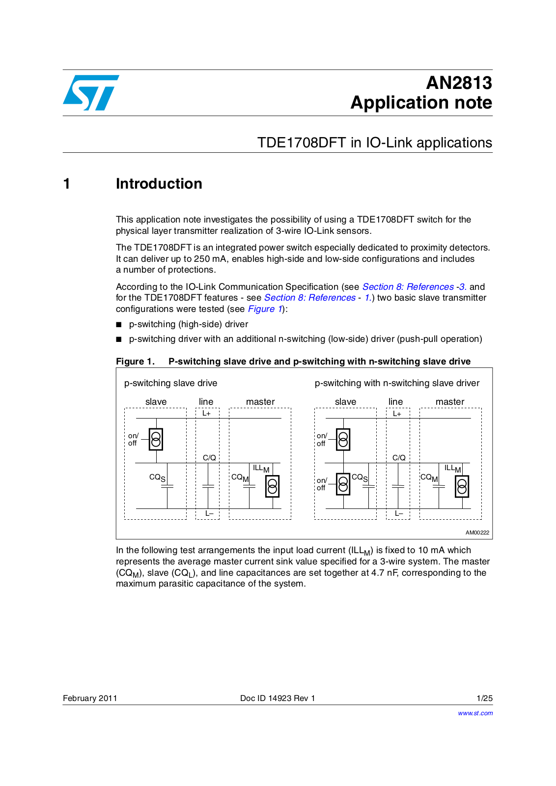
According to the IO-Link Communication Specification (see Section 8: References -3. and for the TDE1708DFT features - see Section 8: References - 1.) two basic slave transmitter configurations were tested (see Figure 1):

p-switching (high-side) driver

p-switching driver with an additional n-switching (low-side) driver (push-pull operation)

Figure 1. P-switching slave drive and p-switching with n-switching slave drive

P SWITCHING SLAVEEDRIVE


P SWITCHING WITHNN SWITCHING SLAVEEDRIVER

SLAVE

LINE

MASTER


SLAVE

LINE

MASTER


,


,


ON


ON


OFF


OFF


# 1


# 1


#13


),,-


),,-


#1-

ON

#13


#1-


OFF


,n


,n


!-

In the following test arrangements the input load current (ILLM) is fixed to 10 mA which represents the average master current sink value specified for a 3-wire system. The master (CQM), slave (CQL), and line capacitances are set together at 4.7 nF, corresponding to the maximum parasitic capacitance of the system.

February 2011

Doc ID 14923 Rev 1

1/25

www.st.com

Contents

AN2813


Contents

1

Introduction . . . . . . . . . . . . . . . . . . . . . . . . . . . . . . . . . . . . . . . . . . . . . . .

. 1

2

TDE1708DFT in high-side configuration . . . . . . . . . . . . . . . . . . . . . . . . .

5


2.1

High-side configuration . . . . . . . . . . . . . . . . . . . . . . . . . . . . . . . . . . . . . . . .

5


2.2

High-side configuration with a capacitive load . . . . . . . . . . . . . . . . . . . . . .

7

3

TDE1708DFT in low-side configuration . . . . . . . . . . . . . . . . . . . . . . . . . .

9


3.1

Low-side configuration . . . . . . . . . . . . . . . . . . . . . . . . . . . . . . . . . . . . . . . .

9


3.2

Low-side configuration with a capacitive load . . . . . . . . . . . . . . . . . . . . .

11

4

Push-pull configuration with TDE1708DFT . . . . . . . . . . . . . . . . . . . . . .

13

5

Performance characteristics . . . . . . . . . . . . . . . . . . . . . . . . . . . . . . . . .

18


5.1

Dynamic information . . . . . . . . . . . . . . . . . . . . . . . . . . . . . . . . . . . . . . . . .

18


5.2

Temperature characteristics . . . . . . . . . . . . . . . . . . . . . . . . . . . . . . . . . . .

18

6

Alternative driving . . . . . . . . . . . . . . . . . . . . . . . . . . . . . . . . . . . . . . . . . .

19


6.1

Temperature characteristics . . . . . . . . . . . . . . . . . . . . . . . . . . . . . . . . . . .

22

7

Conclusion . . . . . . . . . . . . . . . . . . . . . . . . . . . . . . . . . . . . . . . . . . . . . . . .

24

8

References . . . . . . . . . . . . . . . . . . . . . . . . . . . . . . . . . . . . . . . . . . . . . . . .

24

9

Revision history . . . . . . . . . . . . . . . . . . . . . . . . . . . . . . . . . . . . . . . . . . .

24

2/25

Doc ID 14923 Rev 1

AN2813

List of tables


List of tables

Table 1. Push-pull configuration dynamic information

(VCC = 24 V; TJ = 25 °C; CL = 4.7 nF) . . . . . . . . . . . . . . . . . . . . . . . . . . . . . . . . . . . . . . . . 15 Table 2. Dynamic information (VCC = 24 V; TJ = 25 °C; IL = 10 mA) . . . . . . . . . . . . . . . . . . . . . . . . 18 Table 3. Document revision history . . . . . . . . . . . . . . . . . . . . . . . . . . . . . . . . . . . . . . . . . . . . . . . . . 24

Doc ID 14923 Rev 1

3/25

List of figures

AN2813


List of figures

Figure 1.

P-switching slave drive and p-switching with n-switching slave drive. . . . . . . . . . . . . . . . .

. 1

Figure 2.

High-side switch test configuration schematic . . . . . . . . . . . . . . . . . . . . . . . . . . . . . . . . . .

. 5

Figure 3.

High-side switch configuration turn-on behavior . . . . . . . . . . . . . . . . . . . . . . . . . . . . . . . .

. 6

Figure 4.

High-side switch configuration turn-off behavior . . . . . . . . . . . . . . . . . . . . . . . . . . . . . . . .

. 6

Figure 5.

High-side switch test configuration schematic with a capacitive load . . . . . . . . . . . . . . . . .

. 7

Figure 6.

High-side switch configuration with a capacitive load turn-on behavior . . . . . . . . . . . . . . .

. 8

Figure 7.

High-side switch configuration with a capacitive load turn-off behavior . . . . . . . . . . . . . . .

. 8

Figure 8.

Low-side switch test configuration schematic . . . . . . . . . . . . . . . . . . . . . . . . . . . . . . . . . . .

. 9

Figure 9.

Low-side switch configuration turn-on behavior . . . . . . . . . . . . . . . . . . . . . . . . . . . . . . . . .

10

Figure 10.

Low-side switch configuration turn-off behavior . . . . . . . . . . . . . . . . . . . . . . . . . . . . . . . . .

10

Figure 11.

Low-side switch test configuration schematic with a capacitive load . . . . . . . . . . . . . . . . .

11

Figure 12.

Low-side switch configuration with a capacitive load turn-on behavior . . . . . . . . . . . . . . .

12

Figure 13.

Low-side switch configuration with capacitive load turn-off behavior . . . . . . . . . . . . . . . . .

12

Figure 14.

Push-pull test configuration schematic . . . . . . . . . . . . . . . . . . . . . . . . . . . . . . . . . . . . . . . .

14

Figure 15.

Push-pull configuration with capacitive load rising edge . . . . . . . . . . . . . . . . . . . . . . . . . .

15

Figure 16.

Push-pull configuration with capacitive load falling edge . . . . . . . . . . . . . . . . . . . . . . . . . .

16

Figure 17.

Software timing example . . . . . . . . . . . . . . . . . . . . . . . . . . . . . . . . . . . . . . . . . . . . . . . . . .

17

Figure 18.

Propagation turn-on time vs. temperature . . . . . . . . . . . . . . . . . . . . . . . . . . . . . . . . . . . . .

18

Figure 19.

Propagation turn-off time vs. temperature . . . . . . . . . . . . . . . . . . . . . . . . . . . . . . . . . . . . .

18

Figure 20.

Alternative driving schematics . . . . . . . . . . . . . . . . . . . . . . . . . . . . . . . . . . . . . . . . . . . . . .

20

Figure 21.

Alternative driving timings. . . . . . . . . . . . . . . . . . . . . . . . . . . . . . . . . . . . . . . . . . . . . . . . . .

21

Figure 22.

Delay propagation turn-on time vs. temperature (H. S. configuration) . . . . . . . . . . . . . . . .

22

Figure 23.

Delay propagation turn-on time vs. temperature (L. S. configuration) . . . . . . . . . . . . . . . .

22

Figure 24.

Propagation turn-off time vs. temperature (H. S. configuration) . . . . . . . . . . . . . . . . . . . . .

23

Figure 25.

Propagation turn-off time vs. temperature (L. S. configuration) . . . . . . . . . . . . . . . . . . . . .

23

4/25

Doc ID 14923 Rev 1

1 Rev 14923 ID Doc

5/25

GENERATOR

VOLTAGE LEVEL 6 PULSEL WIDTHD FREQUENCYU K(Z


HIGH SIDE DRIVER


5


$4$%&4


62%' 6

6S


, 3 /54

).054


). ,%$$$2)6%2


(3/54

#


$%,!9


'.$


N&


'.$

'.$

'.$


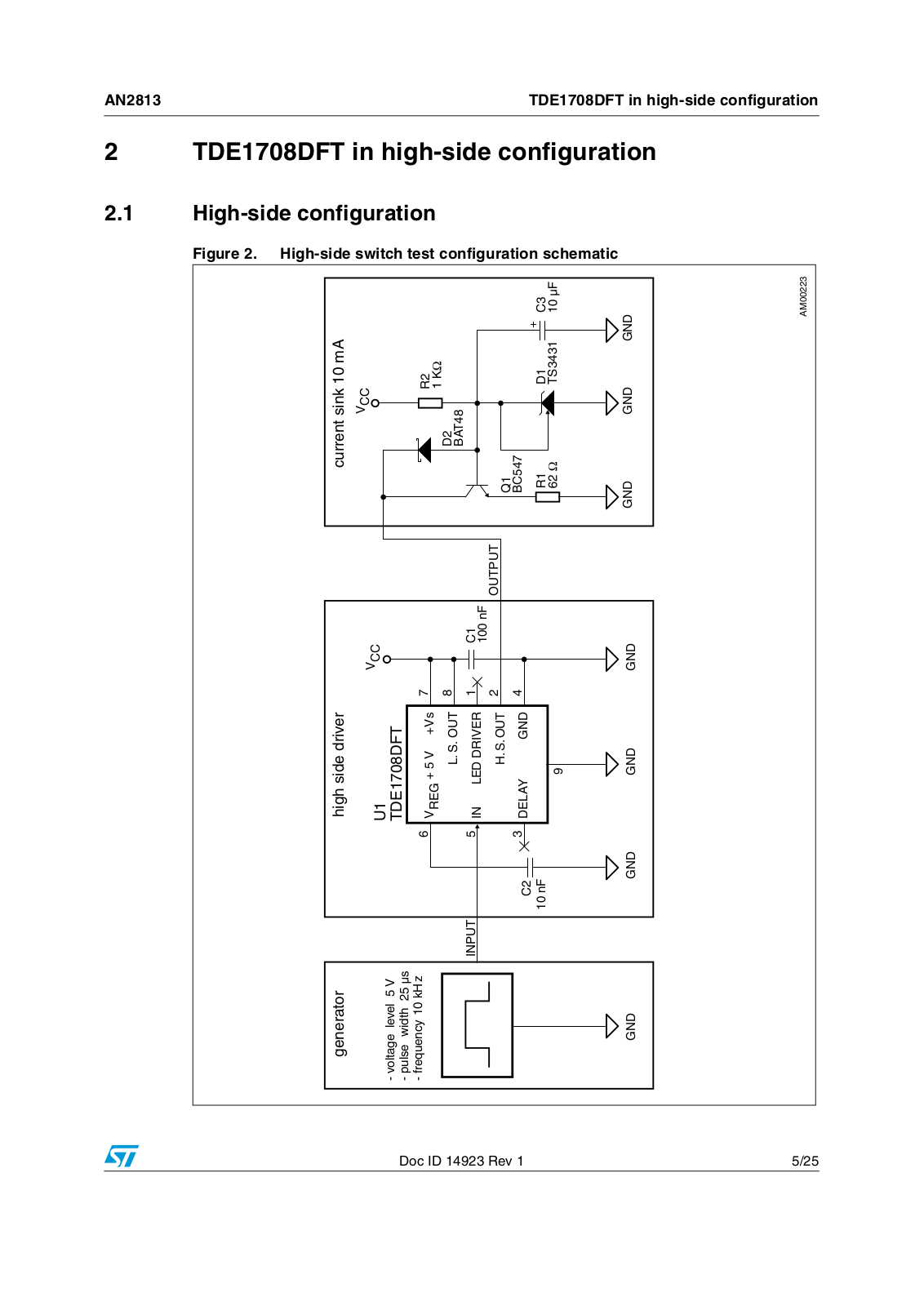
schematicconfigurationtestswitchside-High .2 Figure

1.2

2

AN2813


CURRENTRSINK M!

configurationside-High

configurationside-highinTDE1708DFT

highinTDE1708DFT


6##


6##


2


$


#


"!4


N&

/54054


1


"#


$

#


43


'.$

'.$

'.$

'.$


side-


!-


configuration

TDE1708DFT in high-side configuration

AN2813


Figure 3. High-side switch configuration turn-on behavior(1)

1. CH1: input voltage, CH2: output voltage, CH4: output current (x10).

Figure 4. High-side switch configuration turn-off behavior(1)

1. CH1: input voltage, CH2: output voltage, CH4: output current (x10).

6/25

Doc ID 14923 Rev 1


2.2

AN2813

7/25 1 Rev 14923 ID Doc


Figure

High

configurationside-highinTDE1708DFT

GENERATOR


HIGH SIDE DRIVER


#1


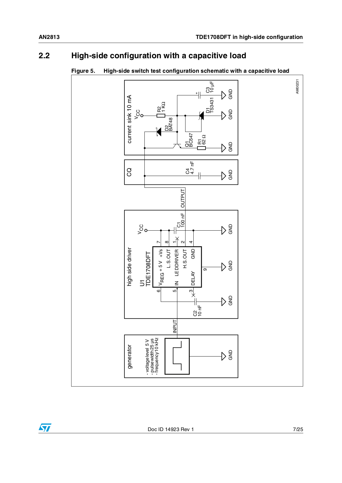
loadcapacitiveawithschematicconfiguration test switch side-High .5

loadcapacitivea with configuration side-


CURRENTRSINK KM!


5


6##


6##


VOLTAGELEVEL 6


4$$%&4


PULSELWIDTHD


FREQUENCYU K(Z


62%' 6 6S


2


,3/54


$


).054


"!4


). ,%$$$2)6%2

#


(3/54


N&

/54054

1


#


$%,!9

'.$


N&

"#


#


N&


2


$

#


43 &


'.$

'.$


'.$


'.$

'.$

'.$

'.$

'.$


!-


ST AN2813 APPLICATION NOTE

TDE1708DFT in high-side configuration

AN2813


Figure 6. High-side switch configuration with a capacitive load turn-on behavior(1)

1. CH1: input voltage, CH2: output voltage, CH4: output current (x10).

Figure 7. High-side switch configuration with a capacitive load turn-off behavior(1)

1. CH1: input voltage, CH2: output voltage, CH4: output current (x10).

8/25

Doc ID 14923 Rev 1

Loading...
+ 17 hidden pages