

Page 1

1 Introduction
This application note describes the easy programmer which is a low cost solution allowing
the content of the STM8A Flash program memory to be updated when the chip is already
soldered on the application board. The easy programmer works by calling the functions of
the bootloader, an IAP application embedded in the system memory of the device (the ROM
memory). Through the bootloader firmware, the device memory can be erased and
programmed using one of the standard communication interfaces present on the particular
device. The easy programmer interfaces the bootloader using a serial port (USART
protocol) with the application board for the upload.
Section 2 of this document gives a brief introduction to the STM8A bootloader. Section 3,
Section 4, and Section 5 describe the easy programmer procedure and its software and
hardware requirements.
For further information on the STM8A family features, pinout, electrical characteristics,
mechanical data and ordering information, please refer to the STM8A128 Kbyte and STM8A
32 Kbyte datasheets. For more details on the bootloader, please refer to the bootloader user
manual (UM0500). All documents are available on st.com.
AN2792
Application note
STM8A easy programmer
This document, its associated firmware, and other such application notes are written to
accompany the STM8S firmware library which is available on st.com.
November 2008 Rev 1 1/12
www.st.com
Page 2

Contents AN2792
Contents
1 Introduction . . . . . . . . . . . . . . . . . . . . . . . . . . . . . . . . . . . . . . . . . . . . . . . . 1
2 Bootloader description . . . . . . . . . . . . . . . . . . . . . . . . . . . . . . . . . . . . . . . 3
2.1 Bootloader flowchart description . . . . . . . . . . . . . . . . . . . . . . . . . . . . . . . . 3
2.2 Peripheral settings . . . . . . . . . . . . . . . . . . . . . . . . . . . . . . . . . . . . . . . . . . . 6
3 Transferring the .s19 file to the easy programmer . . . . . . . . . . . . . . . . . 7
4 Transfering the .s19 file to the STM8A application board . . . . . . . . . . . 8
5 Software and hardware requirements . . . . . . . . . . . . . . . . . . . . . . . . . . . 9
5.1 Batch file . . . . . . . . . . . . . . . . . . . . . . . . . . . . . . . . . . . . . . . . . . . . . . . . . . 9
5.2 Application software . . . . . . . . . . . . . . . . . . . . . . . . . . . . . . . . . . . . . . . . . . 9
5.3 Easy programmer board . . . . . . . . . . . . . . . . . . . . . . . . . . . . . . . . . . . . . . 10
5.4 Application hardware . . . . . . . . . . . . . . . . . . . . . . . . . . . . . . . . . . . . . . . . 10
6 Revision history . . . . . . . . . . . . . . . . . . . . . . . . . . . . . . . . . . . . . . . . . . . 11
2/12
Page 3

AN2792 Bootloader description
2 Bootloader description
The bootloader code is stored in the internal boot ROM memory. Its main task is to
download the application program into the internal memories through the USART, LINUART,
SPI, or CAN peripherals.
The main features of the bootloader are:
● Polling the serial interface (USART and LINUART are both configured as a normal
UART, SPI or CAN) to check which peripheral is used
● Programming code, data, option bytes and/or the vector table at the address(es)
received from the host.
The STM8A reset vector is located at the beginning of the boot ROM (6000h), while the
other vectors are in the Flash program memory starting at address 8004h.
The device jumps inside the boot ROM area and after checking certain address locations
(see Table 1: Initial checking on page 6), it jumps to the reset vector in the Flash program
memory (8000h).
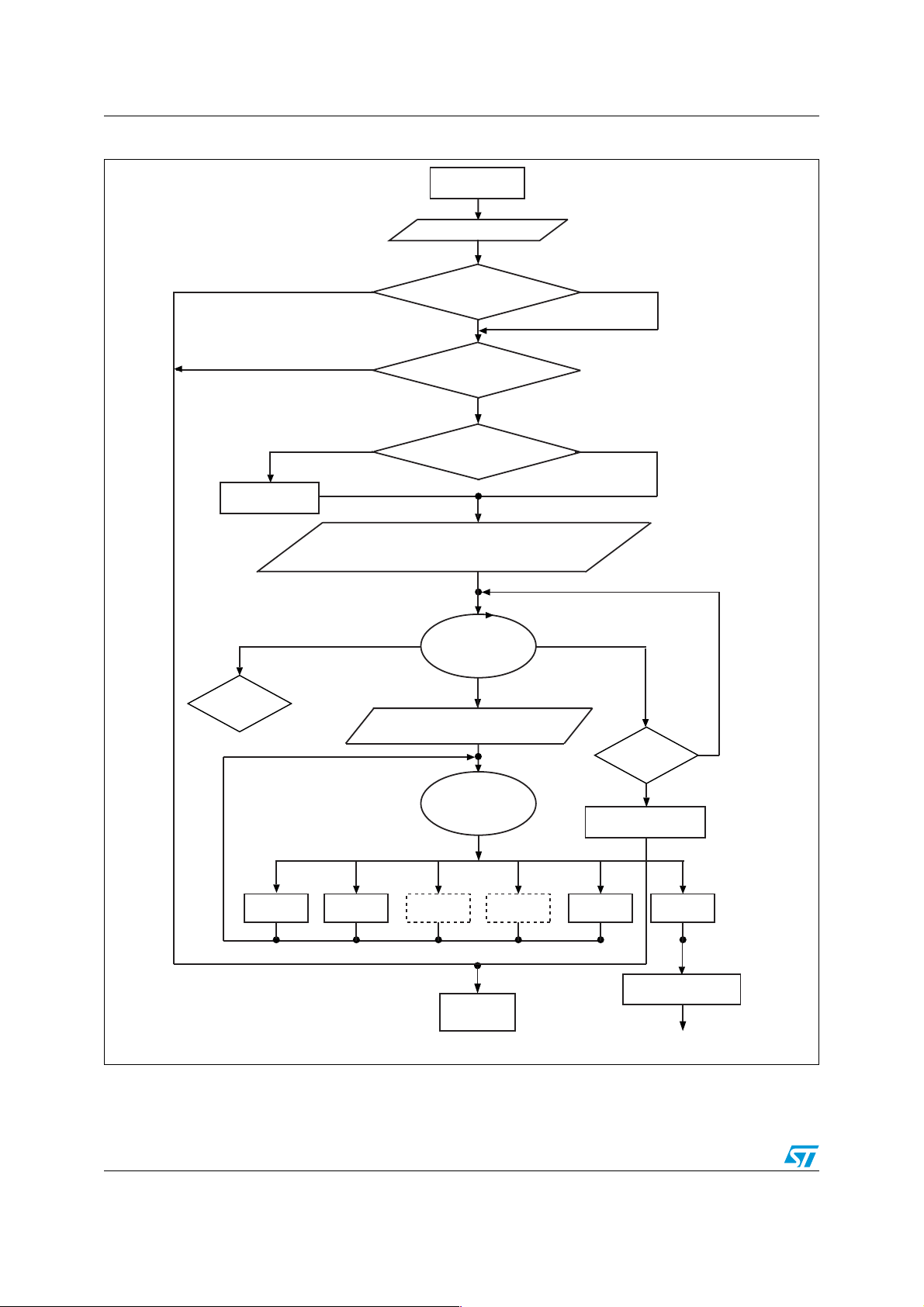
2.1 Bootloader flowchart description
The bootloader activation flowchart is shown in Figure 1 on page 4. The basic steps are
described below.
3/12
Page 4
Bootloader description AN2792
GET cmd
Figure 1. Bootloader activation flowchart
ROM reset
(6000h)
1
Disable all interrupt sources
2
3rd condition verified
Checks according to
Table 1
2nd condition verified
1st condition verified
Yes (memory read out protected)
Ye s No
4
Initializes CAN at
125 kbps
Configure HSI and initialize RX-LINUART pin (PD6) and
RX-USART pin (PDA) in GPIO mofe (pull-up state).
Received a byte/message! = SYNCHR
6
SYNCHR
failed
RM cmd EM cmd
GET cmd
routine
RM cmd
routine
Is ROP active?
No (memory not read out protected)
Is an external clock present?
Configure SPI in slave mode
6
Wait for SYNCHR
SYNCHR received
Send ACK byte and disable unused
peripherals. Execute RASS KEYs
Wait for a command
Command received
EM cmd
routine
Timeout (1 s)
8
WM cmd GO cmd
WM cmd
routine
3
4
7
Is Flash virgin?
Recover the registers
SD cmd
SD cmd
routine
5
No
reset status
6
Ye s
6
GO cmd
routine
Remove EM and WM
Flash reset
(8000h)
routines from the RAM
Jump to host address
ai15000b
1. See flowchart description below for explanation of points 1 to 8.
2. Dotted routines are loaded in RAM by the host. They are removed by the go command before jumping to the Flash program
memory to execute an application.
4/12
Page 5

AN2792 Bootloader description
1. Disable all interrupt sources (any peripheral managed by polling).
2. The host can reprogram the Flash program memory and the bootloader option byte
values as shown in Tab l e 1 according to the content of the first Flash program memory
location (8000h).
3. When read out protection (ROP) is equal to AAh (ROP active), the Flash program
memory is read out protected. In this case, the bootloader stops and the user
application starts. If ROP is not equal to AAh, the bootloader continues to be executed.
4. The CAN peripheral can only be used if an external clock (8 MHz, 16 MHz, or 24 MHz)
is present. It is initialized at 125 kbps. The USART, LINUART, and SPI peripherals do
not require an external clock.
5. Set the high speed internal RC oscillator (HSI) to 16 MHz and initialize the USART and
LINUART receiver pins in input pull-up mode in the GPIO registers. Initialize the SPI in
slave mode.
6. Interface polling: The bootloader polls the peripherals waiting for a synchronization
byte/message (SYNCHR) within a timeout of 1 s. If a timeout occurs, either the Flash
program memory is virgin in which case it waits for a synchronization byte/message in
an infinite loop, or the Flash program memory is not virgin and the bootloader restores
the registers’ reset status before going to the Flash program memory reset vector at
8000h.
Note: When synchronization fails and the bootloader receives a byte/message different
to ‘SYNCHR’, two different situations can be distinguished according to the peripheral:
With USART or LINUART, a device reset or power-down is necessary before
synchronization can be tried again.
With CAN or SPI, the user can continue to poll the interfaces until a synchronization or
a timeout occurs.
7. If the synchronization message is received by the USART or LINUART, the bootloader
detects the baud rate and initializes the USART or LINUART respectively and goes to
step 8 below. If the synchronization message is received by the CAN or SPI, the
bootloader goes directly to step 8 below.
Note: Once one of the available interfaces receives the synchronization message, all
others are disabled.
8. Waiting for commands: Commands are checked in an infinite loop and executed. To exit
from the bootloader, the host has to send a ‘go’ command. When this is done, the
bootloader removes the EM and WM routines from the RAM memory before jumping to
the address selected by the host.
5/12
Page 6

Bootloader description AN2792
Table 1. Initial checking
Checks
st
1
nd
2
rd
3
1. After interface initialization, a write protection test is performed to avoid non-authorised reading of the
Flash program memory/data EEPROM,
Program memory
location 8000h
XXh! = (82h or ACh) XXh XXh
XXh = (82h or ACh) 55h AAh
XXh = (82h or ACh) XXh! = 55h XXh! = AAh
2.2 Peripheral settings
This section describes the hardware setting of the STM8A USART communication
peripheral.
(1)
Bootloader
check
opt_byte 487Eh
Bootloader
check
opt_byteN
487Fh
Actual Flash program
memory status
-> Flash action
Flash program memory
virgin
-> jump to bootloader
Flash program memory
already written
-> jump to bootloader
Flash program memory
already written
-> jump to Flash program
memory reset
Note: LINUART, SPI and CAN peripherals may also be used during bootloading, however, only
one peripheral is enabled at a time; all others are disabled.
Table 2. Serial interfaces associated with STM8A devices
Device Serial interface
128 Kbyte, 96 Kbyte, 64 Kbyte, 48 Kbyte USART, LINUART, CAN
32 Kbyte, 16 Kbyte LINUART, SPI
The USART settings are:
● Data frame: 1 start bit, 8 data bit, 1 parity bit even, 1 stop bit
● Baud rate: The baud rate is autodetected by the bootloader. When the user sends
synchronization byte, 7Fh, the bootloader automatically detects the baud rate and sets
the USART to the same baud rate. Maximum baud rate = 1 Mbps; minimum baud rate
= 4800 bps.
Mandatory: To perform the automatic speed detection, the RX line (PA4) has to be stable in
the application board.
Note: The USART peripheral is accessible via pins PA4 (RX) and PA5 (TX).
6/12
Page 7

AN2792 Transferring the .s19 file to the easy programmer
3 Transferring the .s19 file to the easy programmer
The .s19 file is the application file which the user needs to download to the microcontroller of
the device application board. To do this, it is loaded into the micro SD memory card using
the ‘STxx boatloader tester’ tool.
Synchronizing the easy programmer with the bootloader:
1. Connect the easy programmer board (the STM8A evaluation board USART1 can be
used) to a PC using a cross-serial cable.
2. Switch on /apply power to the easy programmer, press the reset button, press the key
button, and release the reset button until the message ‘start synchronization’ appears
on the display screen.
3. Execute the STxx bootloader tester and set the following configuration in the menu
‘settings’ -> ‘base settings’:
– Port name: Depends on the port of the PC being used
– Baud rate: 115200
– Data bits: 8
– Parity: Even
– Stop bits: 1
4. Press ‘connect’ to send the synchronization character to the microcontroller which
starts the connection. The message ‘connection opened’ in the log window indicates
that the microcontroller is in boot mode and is ready to receive the service requests
from the USART. If this message is not received, steps 1 to 4 should be repeated. The
USART service requests are as follows:
– 00h ? Get
– 11h ? Read memory
– 21h ? Go
– 31h ? Write memory
– 43h ? Erase
Sending .s19 application firmware to the micro SD memory card:
5. Click on ‘open file’ and select the .s19 file (the application file to be transferred).
6. Set the following in the buffer selection window:
– Start address: 00008000h
– End address: The end address of the application (depending on its dimensions).
–Transfer size : 128
7. Select ‘write data/start address’ as 00008000h and press ‘OK’.
8. The message ‘79h’ in the log window indicates that the .s19 file is loaded in the micro
SD memory card of the easy programmer.
9. Click on ‘read data’, set the start address as 8000, and press ‘OK’. An error message is
received, which is normal.
10. If the LCD display message does not read ‘write block finished’, steps 1 to 9 should be
repeated.
11. Press the reset button of the easy programmer.
7/12
Page 8

Transfering the .s19 file to the STM8A application board AN2792
4 Transfering the .s19 file to the STM8A application
board
During this phase the .s19 file is downloaded to the application board of the STM8A. If the
device is virgin, it is already in boot mode, and, the easy programmer can start to read
blocks of 128 bytes from the micro SD memory card and write them in the STM8A memory
using the boot service routine.
If the device is not virgin, and, the easy programmer has not succeeded in synchronizing
with the STM8A after three attempts, the easy programmer sends a pulse on the PH4 pin.
This pulse is captured by the STM8A application board firmware using an external I/O
interrupt. The interrupt routine (see Section 5.2: Application software on page 9) writes two
option bytes (487Eh and 487Fh) and the device is forced into boot mode. Once in boot
mode, the device starts reading and writing blocks, as described above, using the boot
service routine.
The steps are as follows:
1. Connect the easy programmer to the STM8A application board using the connector
described in Section 5.4: Application hardware on page 10.
2. Reset the easy programmer and wait for the LCD to display the message ‘press key to
start transfer’.
3. Press the ‘key’ button of the easy programmer and wait until the LCD displays the
message ‘transfer OK press key’.
4. If no errors occur, the easy programmer is ready to program another device. Otherwise,
if the LCD displays the message ‘ERROR! Boot Mode’, check the connections and
ensure the application firmware contains the interrupt routine described in Section 5.2:
Application software on page 9.
8/12
Page 9

AN2792 Software and hardware requirements
5 Software and hardware requirements
5.1 Batch file
The STxx boot loader tester tool, used to load files into the application board, manages .s19
files in a standard format. There are 16 bytes for single string and increase addresses
options (option -m16 and -s respectively). To produce a .s19 file with both these options, the
following check option must be added:
Es.
"%COS_PATH%\chex" -m16 -s ".\%PRJ_PATH%\%PRJ_NAME%.st7" >
".\PRJ_PATH\%PRJ_NAME%.s19"
COS_PATH is the COSMIC compiler path
PRJ_NAME is the name of the project
5.2 Application software
To program the application board of the STM8A, the device must be in boot mode (see
Section 4: Transfering the .s19 file to the STM8A application board on page 8). If the device
is not in boot mode, the easy programmer must write two option bytes (487Eh and 487Fh).
This is done by the easy programmer sending a pulse on the PH4 pin which is connected to
the external interrupt pin of the application board (PORTx/pin). This external interrupt forces
the application code to execute the interrupt routine that writes the option bytes and resets
the device (the option bytes are updated with the new values only after reset). The interrupt
routine code is as follows:
@interrupt void EXTI_PORTx_IRQHandler (void)
{
volatile u8 opt @0x487E;
volatile u8 nopt @0x487F;
if ( GPIOx.IDR & 0xPin )
{
/* Enable write to EEProm Data */
FLASH.DUNPR = 0xAE;
FLASH.DUNPR = 0x56;
/* Enable write to option byte */
FLASH.CR2 |= 0x80;
FLASH.NCR2 &= 0x7F;
/* Write option byte */
opt = 0x55;
nopt = 0xAA;
/* Reset micro with LSWDG */
IWDG.KR = 0xCC;
IWDG.KR = 0x55;
}
return;
}
‘PORTx’ and ‘pin’ indicate any pin of PORTx with external interrupts. Pins can be chosen
from any available I/0 pin of the application board.
9/12
Page 10

Software and hardware requirements AN2792
5.3 Easy programmer board
The easy programmer is based on firmware, but, to run the code, a hardware platform must
be used where the STM8A microcontroller is interfaced with a USART port, a micro SD
memory card and the easy programmer connector (see Section 5.4: Application hardware
on page 10). In this application note, the STM8A evaluation board is used as an easy
programmer board because all hardware requirements are satisfied. The USART1 is used
to transfer the data, the firmware to be downloaded in the application board microcontroller
is loaded in the Micro SD memory card (64 Mbytes), and the LCD is used to display
messages to control the flow of operations.
5.4 Application hardware
The STM8A device must be uploaded with the easy programmer connection so that data
can be transferred and stimuli sent. Figure 2 shows the easy programmer connections and
Ta bl e 3 gives a description of each of the easy programmer signals.
Figure 2. Easy programmer connections
Easy programmer
U
RX RX
S
A
TX
R
PORTH
PH4 GND
Table 3. Description of the easy programmer signals
T
TX
STM8A application board
U
S
A
R
T
GND Pin
Easy programmer STM8A application board
Pin name Description Pin name Description
RX USART receive TX USART transmit
TX USART transmit RX USART receive
PH4 Stimulus to write option bytes PORTx/pin
External interrupt pin which forces
option bytes to be written
PORTx
GND Ground GND Ground
10/12
Page 11

AN2792 Revision history
6 Revision history
Table 4. Document revision history
Date Revision Changes
03-Nov-2008 1 Initial release
11/12
Page 12

AN2792
Please Read Carefully:
Information in this document is provided solely in connection with ST products. STMicroelectronics NV and its subsidiaries (“ST”) reserve the
right to make changes, corrections, modifications or improvements, to this document, and the products and services described herein at any
time, without notice.
All ST products are sold pursuant to ST’s terms and conditions of sale.
Purchasers are solely responsible for the choice, selection and use of the ST products and services described herein, and ST assumes no
liability whatsoever relating to the choice, selection or use of the ST products and services described herein.
No license, express or implied, by estoppel or otherwise, to any intellectual property rights is granted under this document. If any part of this
document refers to any third party products or services it shall not be deemed a license grant by ST for the use of such third party products
or services, or any intellectual property contained therein or considered as a warranty covering the use in any manner whatsoever of such
third party products or services or any intellectual property contained therein.
UNLESS OTHERWISE SET FORTH IN ST’S TERMS AND CONDITIONS OF SALE ST DISCLAIMS ANY EXPRESS OR IMPLIED
WARRANTY WITH RESPECT TO THE USE AND/OR SALE OF ST PRODUCTS INCLUDING WITHOUT LIMITATION IMPLIED
WARRANTIES OF MERCHANTABILITY, FITNESS FOR A PARTICULAR PURPOSE (AND THEIR EQUIVALENTS UNDER THE LAWS
OF ANY JURISDICTION), OR INFRINGEMENT OF ANY PATENT, COPYRIGHT OR OTHER INTELLECTUAL PROPERTY RIGHT.
UNLESS EXPRESSLY APPROVED IN WRITING BY AN AUTHORIZED ST REPRESENTATIVE, ST PRODUCTS ARE NOT
RECOMMENDED, AUTHORIZED OR WARRANTED FOR USE IN MILITARY, AIR CRAFT, SPACE, LIFE SAVING, OR LIFE SUSTAINING
APPLICATIONS, NOR IN PRODUCTS OR SYSTEMS WHERE FAILURE OR MALFUNCTION MAY RESULT IN PERSONAL INJURY,
DEATH, OR SEVERE PROPERTY OR ENVIRONMENTAL DAMAGE. ST PRODUCTS WHICH ARE NOT SPECIFIED AS "AUTOMOTIVE
GRADE" MAY ONLY BE USED IN AUTOMOTIVE APPLICATIONS AT USER’S OWN RISK.
Resale of ST products with provisions different from the statements and/or technical features set forth in this document shall immediately void
any warranty granted by ST for the ST product or service described herein and shall not create or extend in any manner whatsoever, any
liability of ST.
ST and the ST logo are trademarks or registered trademarks of ST in various countries.
Information in this document supersedes and replaces all information previously supplied.
The ST logo is a registered trademark of STMicroelectronics. All other names are the property of their respective owners.
© 2008 STMicroelectronics - All rights reserved
STMicroelectronics group of companies
Australia - Belgium - Brazil - Canada - China - Czech Republic - Finland - France - Germany - Hong Kong - India - Israel - Italy - Japan -
Malaysia - Malta - Morocco - Singapore - Spain - Sweden - Switzerland - United Kingdom - United States of America
www.st.com
12/12
 Loading...