

Page 1

AN2791
Application note
L9352B coil driver for ABS/ESP applications:
current regulated channel analysis
Introduction
This document describes a detailed analysis on the current regulated channels of the ST
coil driver L9352B. This intelligent quad-low side switch is typically used to drive inductive
loads such as on-off valves of the hydraulic modulator of ABS
(a)
/ESP
(b)
control unit.
a. Antilock Brake System (ABS).
b. Electronic Stability Program (ESP).
June 2008 Rev 1 1/18
www.st.com
Page 2

Contents AN2791
Contents
1 L9352B overview . . . . . . . . . . . . . . . . . . . . . . . . . . . . . . . . . . . . . . . . . . . . 5
2 Test bench layout . . . . . . . . . . . . . . . . . . . . . . . . . . . . . . . . . . . . . . . . . . . 7
3 Linearity relationship test . . . . . . . . . . . . . . . . . . . . . . . . . . . . . . . . . . . . . 8
4 Opening/closing time of the INLET valves versus duty-cycle of the
hold-phase . . . . . . . . . . . . . . . . . . . . . . . . . . . . . . . . . . . . . . . . . . . . . . . . 11
5 Virtual current control loop on the Q1, Q2 channels of L9352B . . . . . 13
6 Revision history . . . . . . . . . . . . . . . . . . . . . . . . . . . . . . . . . . . . . . . . . . . 17
2/18
Page 3

AN2791 List of tables
List of tables
Table 1. INLET valve opening/closing time versus duty-cycle strategy . . . . . . . . . . . . . . . . . . . . . . 12
Table 2. Results of the first operative condition under test. . . . . . . . . . . . . . . . . . . . . . . . . . . . . . . . 14
Table 3. Results of the second operative condition under test . . . . . . . . . . . . . . . . . . . . . . . . . . . . . 14
Table 4. Comparison between the current on loadsdrien by reg. channels and unreg.
channels before and after the VCCL . . . . . . . . . . . . . . . . . . . . . . . . . . . . . . . . . . . . . . . . . 15
Table 5. Results of the last operative condition under test . . . . . . . . . . . . . . . . . . . . . . . . . . . . . . . . 16
Table 6. Document revision history . . . . . . . . . . . . . . . . . . . . . . . . . . . . . . . . . . . . . . . . . . . . . . . . . 17
3/18
Page 4

List of figures AN2791
List of figures
Figure 1. L9352B application diagram . . . . . . . . . . . . . . . . . . . . . . . . . . . . . . . . . . . . . . . . . . . . . . . . . 5
Figure 2. Comparison between the "ideal" linear relationship and the experimental data. . . . . . . . . . 6
Figure 3. Test bench layout used to characterize current control channels of L9352B. . . . . . . . . . . . 7
Figure 4. Current waveform produced on the load by the test coil energizing strategy . . . . . . . . . . . . 8
Figure 5. Comparison between the "ideal" linear relationship and the experimental data
for two different load conditions . . . . . . . . . . . . . . . . . . . . . . . . . . . . . . . . . . . . . . . . . . . . . . 9
Figure 6. Coil current driven by means of L9352B in a typical ABS mission profile: coils on valves . . 9
Figure 7. Coil current driven by means of L9352B in a typical ABS mission profile: stand-alone coils. 10
Figure 8. "Pull-in"- "hold" phase duty-cycle strategy traditionally adopted to drive on-off valves. . . . 11
Figure 9. Evaluation of the VCCL on the L9352B unregulated channels:
first test condition block scheme. . . . . . . . . . . . . . . . . . . . . . . . . . . . . . . . . . . . . . . . . . . . . 13
Figure 10. Evaluation of the VCCL on the L9352B unregulated channels:
last test condition block scheme. . . . . . . . . . . . . . . . . . . . . . . . . . . . . . . . . . . . . . . . . . . . . 15
4/18
Page 5
AN2791 L9352B overview
1 L9352B overview
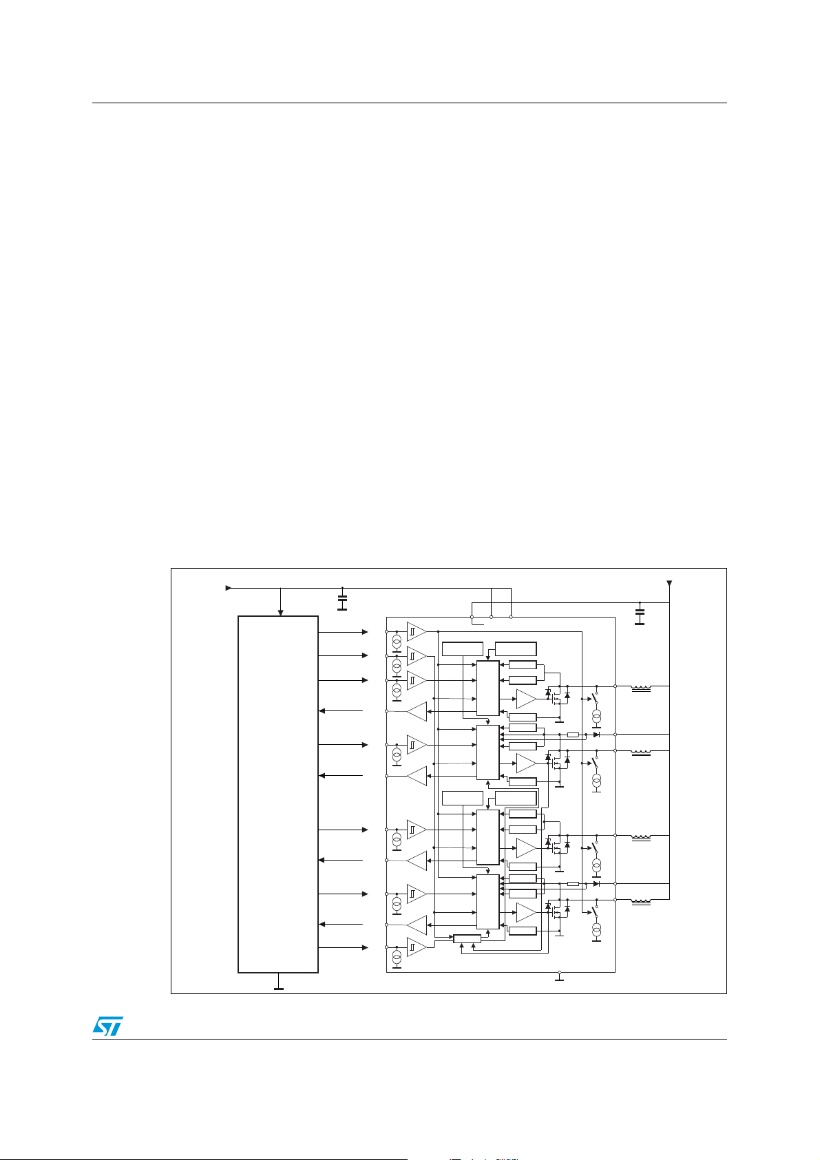
The L9352B (see Figure 1) is designed to drive inductive loads (e.g. relays, electromagnetic
valves, etc.) in low side configuration. Integrated active Zener-clamp, for channels 1 and 2,
or free wheeling diodes, for channels 3 and 4, allow the recirculation of the current of the
inductive loads during the off-state of the DMOS.
All four channels are monitored with a status output. All wiring to the loads and supply pins
of the device are controlled.
The device is self-protected against short circuit at the outputs and over-temperature.
Channels 3 and 4 work as current regulator.
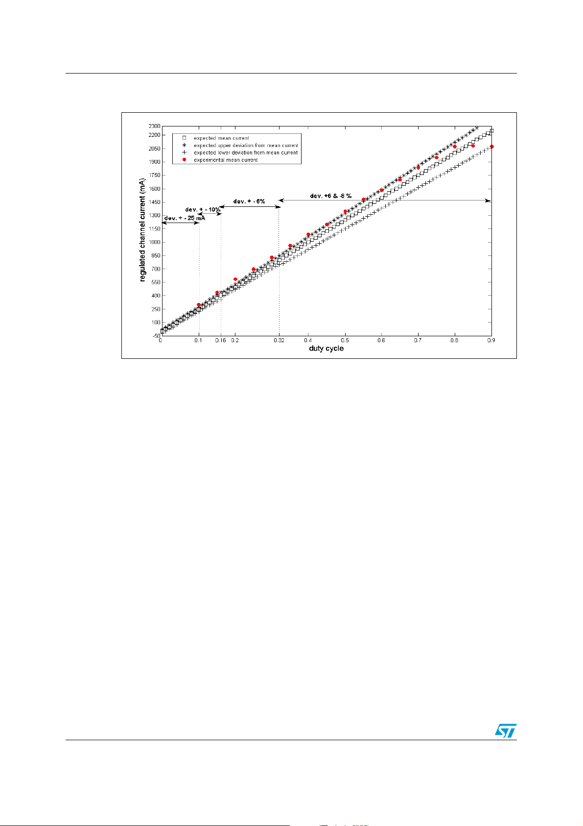
A PWM signal, with a 2 kHz frequency, on the input defines the target for the output current,
in particular, there is a linear relationship between the duty-cycle of the PWM input signal
and the target value of the current (see Figure 2).
The current is measured during recirculation phase of the load, that is, during the off-state of
the DMOS. A sensing resistor, integrated in the IC and placed on the drain of the DMOS and
of the free-wheeling diode, is devoted to measure the current.
The benefit of the current regulation is an optimization of the PWM duty-cycle strategy
against changes in the load conditions (e.g. temperature gradient and as a consequence
coil resistor increases). Moreover, a test mode compares the differences between the two
regulators. This "drift" test compares the output PWM of the regulators. Using this feature a
drift of the load during lifetime can be detected.
Figure 1. L9352B application diagram
5 V logic supply
EN
CLK
IN1
ST1
IN4
ST4
Microcontroller
IN2
ST2
IN3
ST3
TEST
VS VCC VDD
Overtemperature
Channel 4
LOGIC
LOGIC
Overtemperature
Channel 3
LOGIC
LOGIC
drift-det.
Internal Supply
Overtemperature
Channel 1
&
DA
Overtemperature
Channel 2
&
DA
Open Load
Overload
GND-det.
Open Load
Overload
GND-det.
Open Load
Overload
GND-det.
Open Load
Overload
GND-det.
Vbatt
Q1
Free wheeling valve
IPD
D4
Q4
Regulated valve
IPD
Q2
Free wheeling valve
IPD
D3
Q3
Regulated valve
IPD
GND
5/18
Page 6
L9352B overview AN2791
Figure 2. Comparison between the "ideal" linear relationship and the experimental
data
6/18
Page 7

AN2791 Test bench layout
2 Test bench layout
As shown in the Figure 2, the accuracy in the current control of the L9352B depends on the
range of values of the PWM input signal duty-cycle. Basically, for duty-cycle greater than
16% it is possible to consider a current control accuracy of 6 %. The experimental data
shown in the Figure 2 (i.e. red point) are related to the following test layout (see Figure 3):
● dSPACE Microautobox
● LEM Sensor LAH 25-NP
● INLET valves of the 8.0 ABS/ESP Bosch control unit
● coils with a resistor of 4.6 Ohm
● coil energizing frequency (i.e. valve opening/closing frequency) of 5 Hz
● coil energizing strategy:
– for the first 20 ms, duty-cycle = 0.1 %
– for the next 30 ms, duty-cycle = 90 %
– for the last 150 ms, duty-cycle = [5:5:90] %
The current waveform produced by this coil energizing strategy is shown in the Figure 4.
Figure 3. Test bench layout used to characterize current control channels of
L9352B.
7/18
Page 8

Linearity relationship test AN2791
3 Linearity relationship test
The measurements of the values of the mean current to compare with the "ideal" linear
relationship of the L9352B current control channels have been carried out on the "hold-
phase" of the current waveform. The Figure 5 describes a comparison between the results
obtained on two different loads:
● stand-alone coils (i.e. blue stars, crosses and balls);
● coils on the valves (i.e. red stars, crosses and balls);
The main difference between the two considered different load conditions is that for the coils
stand alone you have an equivalent R-L circuit with a fixed inductance.
On the other hand, when as load you consider a coil on a valve, from the point of view of the
equivalent R-L circuit there is an inductance changing with the opening/closing dynamics of
the valve.
As the results of our analysis show in the Figure 5, 6 and 7 the current control loop of the Q3
and Q4 channels has been conceived in order to drive variable inductance loads, in fact, the
spread between maximum and minimum values of the current for a fixed duty-cycle value of
the PWM input signal is minimum in the case of a variable inductance load.
Figure 4. Current waveform produced on the load by the test coil energizing
strategy
8/18
Page 9

AN2791 Linearity relationship test
Figure 5. Comparison between the "ideal" linear relationship and the experimental
data for two different load conditions
Blue stars, crosses and balls indicate minimum, maximum and mean value of the target current for
stand-alone coils. Red stars, crosses and balls indicate minimum, maximum and mean value of the
target current for coils on valves.
Figure 6. Coil current driven by means of L9352B in a typical ABS mission profile:
coils on valves
9/18
Page 10

Linearity relationship test AN2791
Figure 7. Coil current driven by means of L9352B in a typical ABS mission profile:
stand-alone coils
10/18
Page 11

AN2791 Opening/closing time of the INLET valves versus duty-cycle of the hold-phase
4 Opening/closing time of the INLET
duty-cycle of the hold-phase
The conventional strategy adopted to drive on-off valves used in the hydraulic modulator of
ABS/ESP control unit is described in the Figure 8. The "pull-in" phase corresponds to the
maximum values of duty-cycle applied for the first part of the valve opening/closing time.
This phase guarantees the opening/closing of the valve against stiction phenomena due, for
example, to the aging of the valve, to the dirt into the brake fluid, to the stiffness change of
the valve spring and so on.
The "hold" phase corresponds to the duty-cycle value that is necessary to maintain the valve
opened/closed. Clearly this value is less than that used for the "pull-in" phase, because the
force required to overcome the static friction is greater than the force required to overcome
the dynamic one. Obviously, this kind of duty-cycle strategy is power saving too.
Figure 8. "Pull-in"- "hold" phase duty-cycle strategy traditionally adopted to drive
on-off valves
(a)
valves versus
Several tests have been carried out fixing the coil energizing frequency at 5 Hz and the time
strategy at:
● for the first 20 ms, duty-cycle = 0.1 %
● for the next 30 ms, duty-cycle = 90 %
● for the last 150 ms, duty-cycle = [5:5:90] %
The different duty-cycle configurations considered are summarized on the first column of the
Tab l e 1 . In these tests, we measured the opening and closing time of the INLET valve, and,
in addition, the time in which armature-piston of the valve starts its motion. An interesting
result comes out. While the armature-piston motion and the closing time of the INLET valve
are not affected by the duty-cycle configurations, the opening time is affected. In particular,
this increases of 0.5 ms for each 5 % of duty-cycle increase of the "hold" phase.
a. Take into account that the INLET valves of an ABS/ESP hydraulic modulator are on-off valves normally opened and
normally controlled by a current control loop. On the hydraulic modulator there are also OUTLET valves. These valves
normally closed do not require a current control loop but conventional low-side switch.
11/18
Page 12

Opening/closing time of the INLET valves versus duty-cycle of the hold-phase AN2791
Table 1. INLET valve opening/closing time versus duty-cycle strategy
Duty-cycle strategy
[“pull-in”_”hold”]
Armature-piston
motion [ms]
Closing time [ms] Opening time [ms]
20_75 1.5 7 5
20_80 1.5 6.5 5
20_85 1.5 6 5
20_90 1.5 6 5
25_75 1.5 7 5.5
25_80 1.5 6.5 5.5
25_85 1.5 6 5.5
25_90 1.5 6 5.5
30_75 1.5 7 6
30_80 1.5 6.5 6
30_85 1.5 6 6
30_90 1.5 6 6
35_75 1.5 7 6.5
35_80 1.5 6.5 6.5
35_85 1.5 6 6.5
35_90 1.5 6 6.5
12/18
Page 13

AN2791 Virtual current control loop on the Q1, Q2 channels of L9352B
5 Virtual current control loop on the Q1, Q2 channels of
L9352B
In this section we describe an analysis, done on the unregulated channels Q1, Q2 of the
L9352B, aimed to understand the limits of a virtual current control loop on the same
channels. The idea is to tune the duty-cycle of the Q
the duty-cycle observed on the regulated channels Q
load conditions, that is, for both the regulated and unregulated channels of the L9352B, we
considered same coils, same INLET valves. Furthermore, to balance the difference of PWM
signal frequency on the L9352B channels, the unregulated ones (i.e. Q
driven with a frequency of 3.9 kHz
off-state of the Q
, Q2 channels, external free-wheeling diodes have been used to link the
1
(b)
. In order to allow the current recirculation during the
channel output and Vbat. As free-wheeling diode we have considered the ST power Shottky
diodes 1N5817.
Figure 9. Evaluation of the VCCL on the L9352B unregulated channels: first test
condition block scheme
, Q2 channels on a measurement of
1
, Q4. Clearly, we considered same
3
, Q2) have been
1
As first operative condition for our tests (see Figure 9) we can refer to the following data:
● INLET valve opening/closing frequency of 1Hz
● for the first 450 ms, duty-cycle = 0.1 %
● for the next 50 ms, duty-cycle = 90 %
● for the last 500 ms, duty-cycle =[ 15:10:75] %
The Tab l e 2 shows the results related to this first operative condition that we considered for
our tests. As we can see in the last four columns, the difference between the mean current
on the load driven by the unregulated channel and the mean current on the load driven by
the regulated channel reduces as the set-point, that is, the duty of the hold phase increases.
b. Take into account that the ideal frequency of the output PWM signal of the current regulated channels (i.e. Q3,
Q4) is the (clock frequency)/64, that is, 3.9 kHz for a clock frequency of 250 kHz.
13/18
Page 14

Virtual current control loop on the Q1, Q2 channels of L9352B AN2791
Similar results have been observed considering another operative condition, characterized
by a different duty-cycle strategy (see Tab l e 3). Clearly, the duty-cycle applied on the
unregulated channels in both the operative conditions under test is the same measured on
the regulated channel. See columns 2, 3 of the following tables to understand the difference
between the two duty-cycles applied on the unregulated and regulated channels of the
L9352B on the same load conditions.
As second operative condition for our tests (see Figure 9) we can refer to the following data:
● INLET valve opening/closing frequency of 1 Hz
● for the first 500 ms, duty-cycle = 0.1 %
● for the last 500 ms, duty-cycle = [15:10:75] %
The Tabl e 2 and 3 show the results of a comparison between the mean current on the loads
driven by the regulated channels of L9352B and the unregulated ones. These last have
been trained on the output duty-cycle of the regulated channels.
Table 2. Results of the first operative condition under test
Input duty
(hold phase)
Unreg. ch.
output duty
(before the
regulation)
manual
Reg. ch.
output duty
Unreg. ch.
mean current
[mA]
Unreg. ch.
pk-to-pk
current [mA]
Reg. ch.
mean current
[mA]
Reg. ch.
pk-to-pk
current [mA]
0.15 0.83 0.75 520 280 390 360
0.25 0.73 0.65 749 360 660 360
0.35 0.64 0.53 990 400 920 480
0.45 0.55 0.41 1200 480 1200 480
0.55 0.44 0.26 1480 480 1480 480
0.65 0.35 0.1 1700 480 1740 440
0.75 0.23 0.09 1780 520 1760 480
Table 3. Results of the second operative condition under test
Unreg. ch.
Input duty
(hold phase)
output duty
(before the
manual
Reg. ch.
output duty
Unreg. ch.
mean current
[mA]
Unreg. ch.
pk-to-pk
current [mA]
Reg. ch.
mean current
[mA]
regulation)
0.15 0.83 0.75 530 320 390 360
0.25 0.73 0.65 780 400 660 360
0.35 0.64 0.53 980 440 920 440
0.45 0.53 0.39 1240 480 1200 480
0.55 0.44 0.25 1460 560 1480 520
Reg. ch.
pk-to-pk
current [mA]
0.65 0.34 0.09 1630 440 1740 480
0.75 0.25 0.09 1630 440 1820 480
Just to highlight the results obtained by this analysis, it is important to summarize the
difference in the coil current of the unregulated channels of L9352B before and after the
14/18
Page 15

AN2791 Virtual current control loop on the Q1, Q2 channels of L9352B
regulation inspired to the duty-cycle value carried out by the regulated channels of the same
device.
In Ta b l e 4 we can see the results of a comparison between the mean current on the loads,
driven by the L9352B regulated channels and L9352B unregulated channels before and
after the VCCL regulation.
Table 4. Comparison between the current on loadsdrien by reg. channels and unreg. channels
before and after the VCCL
Mean current on the
Hold phase duty
0.35 530 450 560
0.45 660 550 670
cycle-time for the reg. ch.
[mA]
Mean current on the cycle-
time for the unreg. ch. –-
before the regulation -- [mA]
Mean current on the cycle-
after the regulation -- [mA]
As last operative condition considered in our tests we can refer to the following data and the
Figure 10:
● INLET valve opening/closing frequency of 1 Hz
● for the first 450 ms, duty-cycle = 0.1 %
● for the next 50 ms, duty-cycle = 90 %
● for the last 500 ms, duty-cycle = [15:10:75] %
The main idea is to increase the resistance of the loads of about the 15 %. The initial value
of 4.8 Ohm, that is, 4.6 Ohm of the coil resistor plus 0.2 Ohm of Rds-ON of the DMOS has
been increased of 0.6 Ohm. So doing, we simulated a gradient temperature of about 35°.
For this calculation we referred to the formula of the resistance of the chopper versus the
temperature:
R
last
= R
(1 + 0.004ΔT)
initial
From the results shown in the table 7-4, it comes out that the unregulated channels
maintains a satisfactory tracking capability of the current values driven on the loads also in
simulated conditions of temperature gradient.
time for the unreg. ch. –-
Figure 10. Evaluation of the VCCL on the L9352B unregulated channels: last test
condition block scheme
15/18
Page 16

Virtual current control loop on the Q1, Q2 channels of L9352B AN2791
In Ta b l e 5 comparison between the mean current on the loads driven by the regulated
channels of L9352B and the unregulated ones. These last have been trained on the output
duty-cycle of the regulated channels.
Table 5. Results of the last operative condition under test
Input duty
(hold phase)
0.15 0.83 0.73 500 220 400 260
0.25 0.73 0.6 730 280 670 300
0.35 0.64 0.46 1000 380 945 360
0.45 0.54 0.32 1180 440 1220 400
0.55 0.44 0.09 1400 480 1480 400
0.65 0.35 0.09 1400 480 1620 440
0.75 0.23 0.09 1400 480 1600 400
Unreg. ch.
output duty
(before the
regulation)
manual
Reg. ch.
output duty
Unreg. ch.
mean current
[mA]
Unreg. ch.
pk-to-pk
current [mA]
Reg. ch.
mean current
[mA]
Reg. ch.
pk-to-pk
current [mA]
16/18
Page 17

AN2791 Revision history
6 Revision history
Table 6. Document revision history
Date Revision Changes
25-Jun-2008 1 Initial release.
17/18
Page 18

AN2791
Please Read Carefully:
Information in this document is provided solely in connection with ST products. STMicroelectronics NV and its subsidiaries (“ST”) reserve the
right to make changes, corrections, modifications or improvements, to this document, and the products and services described herein at any
time, without notice.
All ST products are sold pursuant to ST’s terms and conditions of sale.
Purchasers are solely responsible for the choice, selection and use of the ST products and services described herein, and ST assumes no
liability whatsoever relating to the choice, selection or use of the ST products and services described herein.
No license, express or implied, by estoppel or otherwise, to any intellectual property rights is granted under this document. If any part of this
document refers to any third party products or services it shall not be deemed a license grant by ST for the use of such third party products
or services, or any intellectual property contained therein or considered as a warranty covering the use in any manner whatsoever of such
third party products or services or any intellectual property contained therein.
UNLESS OTHERWISE SET FORTH IN ST’S TERMS AND CONDITIONS OF SALE ST DISCLAIMS ANY EXPRESS OR IMPLIED
WARRANTY WITH RESPECT TO THE USE AND/OR SALE OF ST PRODUCTS INCLUDING WITHOUT LIMITATION IMPLIED
WARRANTIES OF MERCHANTABILITY, FITNESS FOR A PARTICULAR PURPOSE (AND THEIR EQUIVALENTS UNDER THE LAWS
OF ANY JURISDICTION), OR INFRINGEMENT OF ANY PATENT, COPYRIGHT OR OTHER INTELLECTUAL PROPERTY RIGHT.
UNLESS EXPRESSLY APPROVED IN WRITING BY AN AUTHORIZED ST REPRESENTATIVE, ST PRODUCTS ARE NOT
RECOMMENDED, AUTHORIZED OR WARRANTED FOR USE IN MILITARY, AIR CRAFT, SPACE, LIFE SAVING, OR LIFE SUSTAINING
APPLICATIONS, NOR IN PRODUCTS OR SYSTEMS WHERE FAILURE OR MALFUNCTION MAY RESULT IN PERSONAL INJURY,
DEATH, OR SEVERE PROPERTY OR ENVIRONMENTAL DAMAGE. ST PRODUCTS WHICH ARE NOT SPECIFIED AS "AUTOMOTIVE
GRADE" MAY ONLY BE USED IN AUTOMOTIVE APPLICATIONS AT USER’S OWN RISK.
Resale of ST products with provisions different from the statements and/or technical features set forth in this document shall immediately void
any warranty granted by ST for the ST product or service described herein and shall not create or extend in any manner whatsoever, any
liability of ST.
ST and the ST logo are trademarks or registered trademarks of ST in various countries.
Information in this document supersedes and replaces all information previously supplied.
The ST logo is a registered trademark of STMicroelectronics. All other names are the property of their respective owners.
© 2008 STMicroelectronics - All rights reserved
STMicroelectronics group of companies
Australia - Belgium - Brazil - Canada - China - Czech Republic - Finland - France - Germany - Hong Kong - India - Israel - Italy - Japan -
Malaysia - Malta - Morocco - Singapore - Spain - Sweden - Switzerland - United Kingdom - United States of America
www.st.com
18/18
 Loading...