

Page 1

AN2786
Application note
STEVAL-IHI001V1 demonstration board: washing machine
user interface based on the ST7LITE49M and STLED316S
Introduction
The STEVAL-IHI001V1 is a demonstration board designed to simulate the user interface of
a modern washing machine.
The board is based on the low-cost 8-bit ST7LITE49M microcontroller equipped with an I²C
bus interface, and the STLED316S serial interfaced 6-digit LED controller with key-scan.
The demonstration board is designed to work as a stand-alone application, or as a
motherboard for the STEVAL-IHI002V1 daughter board, which features the STMPE1208S
capacitive sensing device and can be plugged into the STEVAL-IHI001V1 to operate as a
capacitive single touch keyboard.
June 2008 Rev 1 1/10
www.st.com
Page 2

Contents AN2786
Contents
1 STLED316S: serial interfaced LED controller with key-scan . . . . . . . . 3
2 Demonstration board application schematic . . . . . . . . . . . . . . . . . . . . . 4
3 Bill of material . . . . . . . . . . . . . . . . . . . . . . . . . . . . . . . . . . . . . . . . . . . . . . 6
4 STEVAL-IHI001V1 demonstration board photos . . . . . . . . . . . . . . . . . . 7
5 References and related materials . . . . . . . . . . . . . . . . . . . . . . . . . . . . . . 8
6 Revision history . . . . . . . . . . . . . . . . . . . . . . . . . . . . . . . . . . . . . . . . . . . . 9
2/10
Page 3
AN2786 STLED316S: serial interfaced LED controller with key-scan
1 STLED316S: serial interfaced LED controller with
key-scan
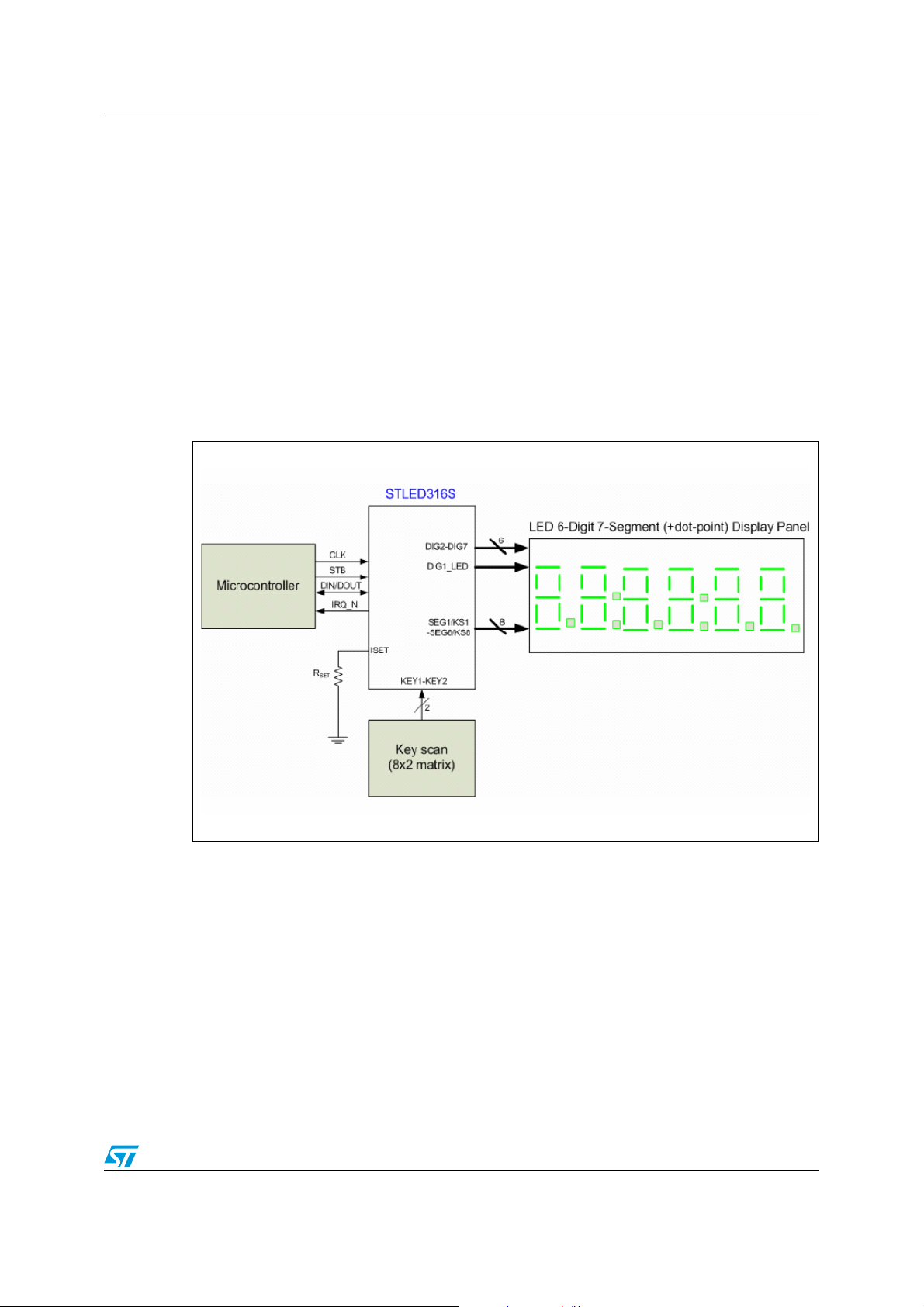
The device used for the washing machine user interface is a compact LED controller and
driver. It interfaces with the MCU through a simple 3-wire serial interface.
The STLED316S drives up to 56 LEDs connected in a common anode configuration.
Individual digits may be addressed and updated directly, without re-writing the entire display
panel.
The maximum segment current is set through a single external resistor (R
Additionally, the STLED316S includes key scanning for an 8x2 key matrix, which
automatically scans a matrix of up to 16 keys.
Figure 1. Product application diagram example
SET
).
The STLED316S is equipped with an internal display RAM memory to store the data
transmitted from the MCU through the serial interface.
The device is programmed through a variety of read/write commands that permit the user to
set the display panel and manage the keyboard.
To avoid scanning the keyboard repeatedly searching for a pressed key, an additional IRQ
signal can be connected to the MCU. An interrupt is generated whenever a key is pressed.
3/10
Page 4

Demonstration board application schematic AN2786
2 Demonstration board application schematic
The demonstration board power supply is designed using a L5970D step-down switching
regulator. The input supply voltage may vary in the range of 5 V to 30 VDC, allowing the
user to connect a standard AC notebook computer power supply. The input is reversepolarity protected (D6), and over-voltage protected (TR1).
The power supply output voltage is set at 5 VDC by mean of 2 resistors (R2, R3).
The ST7LITE49M MCU (U2) runs at 8 MHz by means of an internal oscillator, avoiding the
need for any external components. Pull-up resistors R10 and R11 are used for the I²C bus,
while R12 and R13 prevent the MCU from entering the programming mode unintentionally.
Finally, R14 and R15 set the working mode (MD1, MD2 at logic 1 is "standalone mode").
The LEDs, display and keyboard are entirely managed through U3, (STLED316S). 8
segment lines are multiplexed with 7 digit lines, allowing a total of 56 LEDs (in a common
anode configuration) to be controlled by a single STLED316S device. R4 sets the LED peak
current.
Communication between the MCU and the STLED316S is achieved by means of 3 pins:
data input/output (DIO), clock (CLK) and strobe (STB). An extra IRQ pin generates an
interrupt request any time a key on the keyboard is pressed.
The demonstration board is equipped with connectors J3 and J4 to allow connection to the
STEVAL-IHI002V1 daughter demonstration board. The board is also equipped with ICC
programming connector J2 to program the MCU in-circuit. An extra I²C bus connector (J5) is
foreseen to eventually connect other boards or devices via I²C bus.
4/10
Page 5

AN2786 Demonstration board application schematic
Figure 2. Demonstration board application schematic
2
6
10
1
8
f
e
g
dp
A2
DIG4
DY3
Comm on Anode
d9c7b5a
DIG3
3
A1
DY2
Common Anode
A2
8
DIG3
10
e
DY1
Common Anode
d9c7b5a
SEG8
SEG7
SEG6
SEG5
SEG4
SEG3
SEG2
SEG1
A1
4
3
4
d9c7b5a
e10f2g1dp
6
2
1
6
8
f
g
dp
A2
DIG2
A1
4
3
DL24
R4
DL23
DL21
DL19
DL17
DL15
DL13
DL11
DL9
DL7
DL5
DL3
DL1
390 1%
DL22
DL20
DL18
DL16
DL14
DL12
DL10
24
ISET
DIG7
DIN/DOUT1CLK2STB3IRQ_N4DIG1/LED5DIG26DIG37DIG4
U3
STLED316S
DIO
DIG6
DL8
DL6
DL4
DL2
DIG5
R15
10K
5%
R14
10K
5%
R13
10K
5%
+VDD
R12
10K
5%
MD1
MD2
22
PC1/AI N923PC0/AI N8
VSS9OSC1/CLKIN
C7
+
C5
C8
D1 1N4148
1
2
1
2
1
2
1
2
1
2
10
100nF
10uF
10nF
SEG1
BUZ
DIO
CLK
STB
IRQ
18
17
PB7/AIN721PB6/AIN620PB5/AIN519PB4/AIN4
OSC211VSSA12VDDA13AIN0/PB014CKIN/AIN1/PB1
+VDD
16V
SEG2
D2 1N4148
P1
TACT-2
4
3
P2
TACT-2
4
3
P3
TACT-2
4
3
P4
TACT- 2
4
3
P5
TACT- 2
4
3
R5
10K
5%
PB3/AIN3
GINT
ICCC
ICCD
TINT
PA2
24
25
27
26
29
32
30
31
PC628PC5
PA0(HS)
PC4/LTIC
PC7/BREAK
PC3/ICCC LK
PA1(HS)/ATIC
PA2(HS)/ATPWM
ATPWM1/PA3(HS)1ATPWM2/MCO/PA4(HS)2ATPWM3/PA5(HA)3I2CDATA/PA6(HS)4I2CCLK/PA7(H S)5RESET6NC7VDD
U2
ST7FLI49MK1T6
RST0
PA4
PA3
R11
4K7
5%
+VDD
R10
4K7
5%
SEG1
SEG2
SEG3
SEG4
SEG1/KS121SEG2/KS220SEG3/KS319SEG4/KS4
DIG1
DIG2
QST
DL25
SEG5
17
18
16
GND
VCC9DIG5
8
DIG4
DIG3
+VDD
DL31
STAND ALONE
DL29
DL27
KEY1
KEY2
22
KEY123KEY2
IRQ
STB
CLK
SEG8
SEG7
SEG6
SEG5
SEG4
SEG3
SEG2
SEG1
PC2/ICCDATA
8
I2CD
I2CC
RST
+VDD
SEG6
SEG7
SEG8
15
SEG8/KS813SEG7/KS714SEG6/KS6
SEG5/KS5
DIG611DIG7
12
10
DIG5
DIG6
DIG7
C6
100nF
DL32
S-TOUCH
DL30
DL28
DL26
KEY1
DIG1
J4
CON10
123456789
+VDD
TP3
J3
CON15
123456789
+VDD
AIN2/PB2
15
16
SEG3
SEG4
SEG5
D3 1N4148
D4 1N4148
D5 1N4148
P6
1
2
P7
1
2
P8
1
2
P9
1
2
P10
1
2
R6
10
TP4
1011121314
15
PA4
I2CC
I2CD
RST0
PA3
PA2
MD1
TINT
GINT
MD2
+VDD
TP2
TP1
+VDD
BZ1
+VDD
MD2
12345678910
J5
CON10A
TACT-2
4
3
TACT-2
4
3
TACT-2
4
3
TACT- 2
4
3
TACT- 2
4
3
10K
5%
I2C Expander
I2CD
I2CC
RST0
MD1
RST
+VDD
21
L1
33uH
1
OUT
VCC8VREF
U4
L5970D
6
D6
1N4007
123
KEY2
J1
CON3
BUZ
R9
4K7 5%
R8
10K
5%
Q1
1
2
BC337
Buzzer
+VDD
12345678910
J2
CON10A
R2
15K
1%
5
FB
GND
7
INH
3
SYNC2COMP
4
C3
C2
5V-30V
INPUT
ICCD
22nF
220pF
TR1
ICC Programmer
RST
ICCC
C4
100uF
16V
+
R3
4K7
1%
D7
STPS340U
R1
4K7
C1
10uF
35V
SMAJ33A-TR
5/10
Page 6

Bill of material AN2786
3 Bill of material
Table 1. Bill of material
Item Qty Reference Part Manufacturer
1 1 BZ1 Buzzer KPE242
2 1 C1 10 µF 35 V SMD EPCOS
3 1 C5 10 µF 10 V SMD EPCOS
4 1 C2 220 pF 0805 SMD
5 1 C3 22 nF 0805 SMD
6 1 C4 100 µF 16 V SMD EPCOS
7 2 C6, C7 100 nF 0805 SMD
8 1 C8 10 nF 0805 SMD
9 32 DL1-DL32 L-LTL4231N
10 3 DY1, DY2, DY3 HD-A552RD common anode
11 5 D1, D2, D3, D4, D5 1N4148 DO-35
12 1 D6 1N4007 DO-41
13 1 D7 STPS340U STMicroelectronics
14 1 J1 K375A connector
15 2 J2, J5 MLW10G 10 pin connector
16 1 J3 BL815G 15 pin connector
17 1 J4 BL810G 10 pin connector
18 1 L1 DO3316P-333MLB 33 µH Coilcraft
19 10 P1-P10 P-B1720C push-button
20 1 Q1 BC337 TO-92
21 3 R1, R10, R11 4K7 0805 SMD
22 2 R3, R9 4K7 1206 SMD
23 1 R2 15 kΩ 1206 SMD
24 1 R4 390 1206 SMD
25 3 R5, R6, R8 10 kΩ 1206 SMD
26 4 R12, R13, R14, R15 10 kΩ 0805 SMD
27 1 TR1 SMAJ33A-TR Transil
28 1 U2 ST7FLI49MK1T6 STMicroelectronics
29 1 U3 STLED316SMTR STMicroelectronics
TM
STMicroelectronics
30 1 U4 L5970D STMicroelectronics
6/10
Page 7

AN2786 STEVAL-IHI001V1 demonstration board photos
4 STEVAL-IHI001V1 demonstration board photos
Figure 3. Front view
Figure 4. Angle view
7/10
Page 8

References and related materials AN2786
5 References and related materials
For further information related to the functionality of the devices mentioned in this
application note, please refer to the following documents:
1. ST7LITE49M datasheet
2. STLED316S datasheet
3. L5970D datasheet
8/10
Page 9

AN2786 Revision history
6 Revision history
Table 2. Document revision history
Date Revision Changes
16-Jun-2008 1 Initial release.
9/10
Page 10

AN2786
Please Read Carefully:
Information in this document is provided solely in connection with ST products. STMicroelectronics NV and its subsidiaries (“ST”) reserve the
right to make changes, corrections, modifications or improvements, to this document, and the products and services described herein at any
time, without notice.
All ST products are sold pursuant to ST’s terms and conditions of sale.
Purchasers are solely responsible for the choice, selection and use of the ST products and services described herein, and ST assumes no
liability whatsoever relating to the choice, selection or use of the ST products and services described herein.
No license, express or implied, by estoppel or otherwise, to any intellectual property rights is granted under this document. If any part of this
document refers to any third party products or services it shall not be deemed a license grant by ST for the use of such third party products
or services, or any intellectual property contained therein or considered as a warranty covering the use in any manner whatsoever of such
third party products or services or any intellectual property contained therein.
UNLESS OTHERWISE SET FORTH IN ST’S TERMS AND CONDITIONS OF SALE ST DISCLAIMS ANY EXPRESS OR IMPLIED
WARRANTY WITH RESPECT TO THE USE AND/OR SALE OF ST PRODUCTS INCLUDING WITHOUT LIMITATION IMPLIED
WARRANTIES OF MERCHANTABILITY, FITNESS FOR A PARTICULAR PURPOSE (AND THEIR EQUIVALENTS UNDER THE LAWS
OF ANY JURISDICTION), OR INFRINGEMENT OF ANY PATENT, COPYRIGHT OR OTHER INTELLECTUAL PROPERTY RIGHT.
UNLESS EXPRESSLY APPROVED IN WRITING BY AN AUTHORIZED ST REPRESENTATIVE, ST PRODUCTS ARE NOT
RECOMMENDED, AUTHORIZED OR WARRANTED FOR USE IN MILITARY, AIR CRAFT, SPACE, LIFE SAVING, OR LIFE SUSTAINING
APPLICATIONS, NOR IN PRODUCTS OR SYSTEMS WHERE FAILURE OR MALFUNCTION MAY RESULT IN PERSONAL INJURY,
DEATH, OR SEVERE PROPERTY OR ENVIRONMENTAL DAMAGE. ST PRODUCTS WHICH ARE NOT SPECIFIED AS "AUTOMOTIVE
GRADE" MAY ONLY BE USED IN AUTOMOTIVE APPLICATIONS AT USER’S OWN RISK.
Resale of ST products with provisions different from the statements and/or technical features set forth in this document shall immediately void
any warranty granted by ST for the ST product or service described herein and shall not create or extend in any manner whatsoever, any
liability of ST.
ST and the ST logo are trademarks or registered trademarks of ST in various countries.
Information in this document supersedes and replaces all information previously supplied.
The ST logo is a registered trademark of STMicroelectronics. All other names are the property of their respective owners.
© 2008 STMicroelectronics - All rights reserved
STMicroelectronics group of companies
Australia - Belgium - Brazil - Canada - China - Czech Republic - Finland - France - Germany - Hong Kong - India - Israel - Italy - Japan -
Malaysia - Malta - Morocco - Singapore - Spain - Sweden - Switzerland - United Kingdom - United States of America
www.st.com
10/10
 Loading...