

Page 1

AN2780
Application note
Real-time keeping on STM8S and STM8A devices
and usage of auto-wakeup unit (AWU) and beeper
Introduction
The purpose of this application note is to explain how to keep real-time information on a
STM8S or STM8A device maintained in low power mode.
Only simple solutions which do not require any additional hardware are described in this
application note. They are suitable for applications which do not need a very accurate realtime measurement.
To benefit fully from the information in this application note, the user should be familiar with
the STM8S and STM8A microcontroller architecture and with the basics of C language.
For further information on the STM8S and STM8A family features, pinout and electrical
characteristics, please refer to the STM8S and STM8A datasheets.
An STM8S and STM8A firmware package is delivered with this application note. It contains
the complete C source code of an example described in this application note, so that the
user can compile, link or modify it as necessary.
This document and its associated firmware package, are written to accompany the STM8S
and STM8A firmware library. It includes many examples describing how to use the STM8S
and STM8A timers, the clock system, the beeper and the auto-wakeup unit mentioned in
this application note.
Related documents (available for download from www.st.com):
AN2780 associated firmware package
STM8S and STM8A firmware library
AN2822 “STM8S and STM8A high speed internal oscillator calibration”
AN2857 “STM8S and STM8A family power management”
AN2645 “Migration and compatibility guidelines for STM8S and STM8A microcontroller
applications”
August 2011 Doc ID 14759 Rev 2 1/20
www.st.com
Page 2

Contents AN2780
Contents
1 Real-time measurement capability . . . . . . . . . . . . . . . . . . . . . . . . . . . . . 5
1.1 Time base common to auto-wakeup unit and beeper . . . . . . . . . . . . . . . . 5
1.2 Solution using the auto-wakeup unit in Active-halt mode . . . . . . . . . . . . . . 6
1.2.1 Introduction . . . . . . . . . . . . . . . . . . . . . . . . . . . . . . . . . . . . . . . . . . . . . . . 6
1.2.2 Description . . . . . . . . . . . . . . . . . . . . . . . . . . . . . . . . . . . . . . . . . . . . . . . . 6
1.3 Solution using the beeper . . . . . . . . . . . . . . . . . . . . . . . . . . . . . . . . . . . . . . 9
1.3.1 Introduction . . . . . . . . . . . . . . . . . . . . . . . . . . . . . . . . . . . . . . . . . . . . . . . 9
1.3.2 Beeper solution implementation . . . . . . . . . . . . . . . . . . . . . . . . . . . . . . . 9
1.4 Other solutions . . . . . . . . . . . . . . . . . . . . . . . . . . . . . . . . . . . . . . . . . . . . . 10
2 Associated software example description . . . . . . . . . . . . . . . . . . . . . . 11
2.1 Main variables, definitions and constants used by the software . . . . . . . . 11
2.1.1 Variables defined in main.c file . . . . . . . . . . . . . . . . . . . . . . . . . . . . . . . 11
2.1.2 Configuration definitions in rtc.h file . . . . . . . . . . . . . . . . . . . . . . . . . . . . 11
2.1.3 Configuration constants defined in STM8S and STM8A firmware
library . . . . . . . . . . . . . . . . . . . . . . . . . . . . . . . . . . . . . . . . . . . . . . . . . . . 12
2.2 Initialization procedures . . . . . . . . . . . . . . . . . . . . . . . . . . . . . . . . . . . . . . 12
2.3 Application interrupt routine . . . . . . . . . . . . . . . . . . . . . . . . . . . . . . . . . . . 12
2.4 Application interface - real-time conversions . . . . . . . . . . . . . . . . . . . . . . 13
2.4.1 First alternative solution: real-time kept continuously . . . . . . . . . . . . . . 14
2.4.2 Second alternative solution: real-time converted on request . . . . . . . . . 14
3 Firmware environment . . . . . . . . . . . . . . . . . . . . . . . . . . . . . . . . . . . . . . 16
4 Test environment . . . . . . . . . . . . . . . . . . . . . . . . . . . . . . . . . . . . . . . . . . . 17
5 Accuracy of the used method . . . . . . . . . . . . . . . . . . . . . . . . . . . . . . . . 18
5.1 Conclusion . . . . . . . . . . . . . . . . . . . . . . . . . . . . . . . . . . . . . . . . . . . . . . . . 18
6 Revision history . . . . . . . . . . . . . . . . . . . . . . . . . . . . . . . . . . . . . . . . . . . 19
2/20 Doc ID 14759 Rev 2
Page 3

AN2780 List of tables
List of tables
Table 1. List of files included in the STM8S and STM8A firmware package . . . . . . . . . . . . . . . . . . 16
Table 2. Revision history . . . . . . . . . . . . . . . . . . . . . . . . . . . . . . . . . . . . . . . . . . . . . . . . . . . . . . . . . 19
Doc ID 14759 Rev 2 3/20
Page 4

List of figures AN2780
List of figures
Figure 1. Time base block diagram for AWU and beeper . . . . . . . . . . . . . . . . . . . . . . . . . . . . . . . . . . 5
Figure 2. AWU block diagram . . . . . . . . . . . . . . . . . . . . . . . . . . . . . . . . . . . . . . . . . . . . . . . . . . . . . . . 6
Figure 3. AWU operation in applications using only AWU interrupts . . . . . . . . . . . . . . . . . . . . . . . . . . 7
Figure 4. AWU operation in applications using the AWU interrupt and other
interrupt source . . . . . . . . . . . . . . . . . . . . . . . . . . . . . . . . . . . . . . . . . . . . . . . . . . . . . . . . . . . 8
Figure 5. Beeper block diagram example . . . . . . . . . . . . . . . . . . . . . . . . . . . . . . . . . . . . . . . . . . . . . . 9
Figure 6. BEEP signal edge external interrupt - example of increment & compare
cycle performed on pair of registers of fx_time structure . . . . . . . . . . . . . . . . . . . . . . . . . . 13
Figure 7. Main loop service checking the one-second events . . . . . . . . . . . . . . . . . . . . . . . . . . . . . . 14
Figure 8. Main loop service checking the real-time update request. . . . . . . . . . . . . . . . . . . . . . . . . . 15
4/20 Doc ID 14759 Rev 2
Page 5
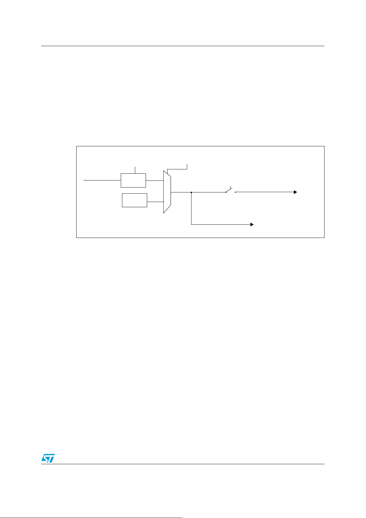
AN2780 Real-time measurement capability
LSI RC
128 kHz
MSR
Prescaler
~ 128 kHz LS clock
option bit
HSE clock
option bits
PRSC[1:0]
(for measurement)
CKAWUSEL
(1 - 24 MHz)
f
LS
to timer input capture
AWU, beeper
1 Real-time measurement capability
1.1 Time base common to auto-wakeup unit and beeper
This application note focuses on solutions using one of the following STM8S and STM8A
peripherals: auto-wakeup unit or beeper. These peripherals share a common 128 kHz clock
(LS clock) which can be driven either by a low speed internal RC oscillator (LSI) or by a high
speed external crystal/ceramic resonator (HSE), depending on the CLKAWUSEL option bit
(see Figure below).
Figure 1. Time base block diagram for AWU and beeper
The HSE and LSI clock sources have different characteristics:
● The HSE source has the advantage of performing more accurate measurements but
the power consumption is higher (increased by about 0.5 mA) as the system must keep
the HSE clock running while it stays in low power mode. The HSE clock can be divided
by setting the PRSC option bits to get a LS clock frequency close to 128 kHz or a lower
frequency.
● The LSI clock system guarantees a much lower power consumption (consumption of
about 5 µA) but it has the disadvantage of being less accurate and highly temperaturedependent (about ±12.5% within the whole temperature range).
The time interval measurement accuracy can be improved by measuring the LSI
frequency internally. This can be performed by connecting the LSI clock to a given timer
input capture through the switch controlled by the MSR bit in the AWU_CSR register
and by setting properly the timer system for input capture capability. TIM3 is the
dedicated timer for this LSI measurement in most STM8S and STM8A devices. TIM1 is
used if TIM3 is not present. Some examples of input capture setting can be found in the
STM8S and STM8A firmware library.
Note: If the LSI clock frequency is measured while the microcontroller is driven by the HSI clock
(internal high speed oscillator), it is possible to achieve a greater accuracy by calibrating the
HSI clock before measuring the LSI frequency. The user can find further information on HSI
calibration in the AN2822 application note
(STM8S and STM8A high speed internal
oscillator calibration).
Doc ID 14759 Rev 2 5/20
Page 6
Real-time measurement capability AN2780
counter
AWU counters
6-bit prog
AWUTB[3:0]
15 time bases
AWU interrupt
AWUEN & HALT/WAIT
APR[5:0]
~ 128 kHz LS clock
1.2 Solution using the auto-wakeup unit in Active-halt mode
1.2.1 Introduction
The basic software principle is to keep track of the number of elapsed time intervals
detected by the AWU. The accumulated time can easily be converted from this data by
loading a structure keeping real-time information either on request or at regular intervals.
1.2.2 Description
The auto-wakeup unit (AWU) provides an internal wakeup time base that is used when the
MCU goes into Active-halt mode. The measurement of this wakeup time can be used to
keep real-time information but some limitations must be considered, as described in the
following sections.
Figure 2. AWU block diagram
Note: As the AL bit in the CFG_GCR register cannot be used in low power mode, when the device
6/20 Doc ID 14759 Rev 2
The AWU time intervals depend on the prescaler value defined in the APR bits of the
AWU_APR register and on the AWUTB bits programmed in the AWU_TBR register. To enter
Active-halt mode, the auto-wakeup unit must be enabled by setting the AWUEN bit in the
AWU_CSR register before HALT instruction execution.
The AWU counters are running and counting only when the device is in Active-halt mode.
They are stopped when the CPU is in Run mode and initialized again when the
microcontroller enters Active-halt mode. This means that the total period is the sum of the
AWU interval (AWU timeout) and the duration of the AWU interrupt routine.
goes back from an interrupt, the user must handle by software the device return to Halt
mode.
Page 7

AN2780 Real-time measurement capability
ai15340
AWU
interrupt
service
AWU
timeout
AWU interrupt
Active-halt mode
entry
AWU
interrupt service
Corrected
AWU
timeout
AWU
period
Halt
Halt
Several cases can be considered (refer to the following sections):
The AWU interrupt is the only interrupt used by the application
1. Constant AWU interrupt service times:
When wakeup events rise at almost equidistant periods, real-time data can be
computed as a simple sum of the AWU periods. Two time measurement methods are
possible in this case:
a) The interrupt service time can be disregarded if it is negligible compared to the
AWU interval.
Time = sum of AWU intervals
b) A small constant correction can be applied to the AWU interval to compensate for
the time spent in AWU interrupt service.
Time = sum of corrected AWU intervals
2. Irregular AWU interrupt service times
Two time measurement methods are also possible in this case:
a) When most AWU services have the same duration, coincidental interrupt services
with significantly different durations can be corrected by changing the duration of
the next AWU interval in order to keep equidistant periods. This is done by
modifying the APR bits in the AWU_APR register and the AWUTB bits in the
AWU_TBR register for the next AWU interval. Time can then be computed like in
case 1.
b) When AWU services always have different durations, the time the microcontroller
spends in Run mode must be measured, registered and summarized. The realtime data can be computed as a sum of all AWU wakeup intervals plus this
summarized Run time.
Time= sum of AWU intervals + sum of all run time procedures
(refer to Figure 3)
Figure 3. AWU operation in applications using only AWU interrupts
Doc ID 14759 Rev 2 7/20
Page 8

Real-time measurement capability AN2780
ai15321
AWU
interrupt
service
AWU
timeout
(Active-halt mode)
Unidentifiable
interval
AWU interrupt
Active-halt mode
entry
Other
interrupt service
AWU
timeout
The AWU interrupt service routine is not the only interrupt service and the
system has to service other interrupt sources
Refer to Figure 4.
This is the most common situation for many applications. As the content of the AWU
counters can never be read, time intervals cannot continue being measured when the
microcontroller has been woken up by a source other than the AWU interrupt source. Then,
there is always an unidentifiable interval between the last entry into Active-halt mode and
the rise of the other interrupt. The time continuity of AWU interrupts is then lost. This is the
main limitation when using AWU for real-time measurement purposes because most
applications need to control several interrupt sources.This limitation restricts the use of the
AWU for real-time measurement in applications where the frequency of interrupts from other
sources is negligible compared to the frequency of AWU wakeup interrupts.
Figure 4. AWU operation in applications using the AWU interrupt and other
interrupt source
8/20 Doc ID 14759 Rev 2
Page 9

AN2780 Real-time measurement capability
BEEPEN
BEEP pin
5-BIT BEEPER PROG
COUNTER
~4 kHz
3-BIT COUNTER
500 Hz
128 kHz LS clock
BEEPDIV[4:0] bits
BEEPSEL[1:0] bits
1.3 Solution using the beeper
1.3.1 Introduction
This section provides a procedure using the BEEP signal for measuring real-time in systems
entering low power modes. The basic software principle is very similar to the procedure
using the AWU. This method uses the output of a low beeper frequency feeding an external
interrupt enabled on the same I/O pin.
The application can easily derive a time base from the beeper frequency, because the
beeper, when activated, is always running regardless of the mode in which the system stays
(low power or run mode).
1.3.2 Beeper solution implementation
The 128 kHz LS clock divided by the beeper divider system is used as a low speed clock
source running permanently. This clock signal acts then as an external interrupt to wake up
the microcontroller from a low power mode. The BEEP output signal and external interrupt
capability can be enabled simultaneously on the BEEP pin (the PD4 pin in STM8S and
STM8A devices) so that no external connection or additional GPIO pin generating external
interrupts is required.
● To enable the BEEP frequency output:
– The proper option byte must be programmed in devices where the BEEP pin is an
optional alternate function.
– The BEEPEN bit in the BEEP_CSR register must be set.
● To enable the interrupt input capability:
– The BEEP pin must be configured as an input with interrupt.
– The external interrupt sensitivity for the BEEP pin port must be set as either “
rising edge only” or “falling edge only”.
– The appropriate interrupt service routine must be called from the corresponding
location in the interrupt vector table.
For low-power systems, it is important to minimize the time spent in run mode and,
consequently, to maximize the time interval between two consecutive beeper interrupts.
Clearing the BEEPSEL[1:0] bits in the BEEP_CSR register while the BEEPDIV bits are set
to 0x1E gives the lowest possible BEEP output frequency (about 500 Hz for 128 kHz LSI LS clock input is first divided by 32 and then by 8), as shown in Figure 5.
Figure 5. Beeper block diagram example
As explained in Section 1.1, the lower accuracy of the LSI source can be compensated by
measuring internally its frequency. When the LS clock signal is measured internally by the
Doc ID 14759 Rev 2 9/20
Page 10

Real-time measurement capability AN2780
dedicated timer, the following formula can be used for calculating the BEEP signal frequency
in case the beeper dividers are selected to provide the lowest output frequency:
f
= f
BEEP
/ (32*8) = (f
LS
/ n) / (32*8)
CNT
where
f
= BEEP signal frequency [Hz].
BEEP
f
= timer counter input frequency [Hz].
CNT
n= number of timer counter counts within LS signal period.
Then the rounded frequency f
counted on the BEEP pin to get the one-second period time base.
The LS measurement accuracy can be increased by setting the input capture prescaler of
the timer to its maximum value (bits ICxPSC = 11 in the TIMx_CCMR register) while the
timer counter is running at a maximum frequency (HSIDIV and CPUDIV bits cleared in the
CLK_CKDIVR register and PSC bits cleared in the TIMx_PSCR register), as described in
the example given in the associated firmware package. Then the number of timer counter
counts matches eight consecutive LS signal periods. The upper formula is simplified in this
case as follows:
f
= f
BEEP
/ (32*8) = (f
LS
where
N = number of timer counter counts during eight consecutive LS signal periods.
1.4 Other solutions
The solutions given in Section 1.2 and Section 1.3 are suitable for applications where realtime is used only as an approximate indication (to track the usage or running time of some
devices, or to record error occurrences for instance). They should not be used for
applications requiring precise real-time measurement.
To keep real-time information more accurately or with consistent measurement in the whole
operating temperature range, another solution should be chosen using an external low
speed crystal oscillator. The user can select a member of the STM8L subfamily where a
real-time clock with low speed external clock source connectivity is included. A wide range
of external components keeping real-time autonomously can also be found. They can easily
be connected to the STM8S or STM8A in most cases via peripherals like I2C (e.g.
M41ST85) or SPI (e.g. M41ST95).
BEEP
*8 / N) / (32*8) = f
CNT
in Hertz is equal to the number of external interrupts
/ (N*32)
CNT
10/20 Doc ID 14759 Rev 2
Page 11

AN2780 Associated software example description
2 Associated software example description
This section describes a software method using the Beeper function as described in
Chapter 1.3. The solution is based on STM8S and STM8A firmware library routines. The
sections below describe the structure of the software example and how it works:
– Variables are listed in Section 2.1.
– The initialization process is described in Section 2.2.
– The interrupt system registering beeper pulses is described in Section 2.3.
– Two alternative examples of how the real-time can be converted from registered
pulses are listed in Section 2.4.1 and Section 2.4.2. The first one keeps real-time
information continuously and the second one calculates it on request only.
The application does not require any external connection. The only hardware limitation
consists in reserving the external connectivity of the BEEP pin for beeper signal output and
external interrupt input purposes.
2.1 Main variables, definitions and constants used by the software
2.1.1 Variables defined in main.c file
● lsi_fqcy ... variable keeping the result of internal measurement of LS clock frequency
[Hz],
● beep_fqcy ... variable keeping result of internal computation of beeper output
frequency used as a one second interval compare limit [Hz],
● edge_day_overflow_limit ... variable keeping computed number of external events
within one day period used as a one day interval compare limit,
● fx_time ... structure filled with the interrupt service registering number of external
events together with the number of overflows of predefined one-second and one-day
limits (edge_second_counter & second_overflow_counter are used for “second”
intervals, edge_day_counter & day_overflow_counter for “day” intervals),
● real_time ... structure keeping converted real-time information (seconds, minutes,
hours and days). The update of this structure is performed in main loop and is based on
the content of the registers in the fx_time structure.
2.1.2 Configuration definitions in rtc.h file
● KEEP_RT ... SW software selection between two alternative solutions.
– If the KEEP_RT constant is defined: real-time information is kept continuously
(updated in one-second intervals) in real_time structure
– If KEEP_RT constant is not defined: it is converted into the structure on request
only (in this case, the request is simulated by key press event)
● MEASURE_ON_HSE ... SW software selection between two alternative solutions.
– If the MEASURE_ON_HSE constant is defined: LSI is measured using the HSE
frequency.
– If the MEASURE_ON_HSE constant is not defined, the HSI frequency is used.
Doc ID 14759 Rev 2 11/20
Page 12

Associated software example description AN2780
2.1.3 Configuration constants defined in STM8S and STM8A firmware library
HSI_VALUE & HSE_VALUE ... constants to determine values of HSI and HSE frequencies.
Note: The accuracy of the LSI value measurement is highly dependent on the difference between
the real value of the HSI or HSE clock frequency and the HSI_VALUE or HSE_VALUE
constant entered as a parameter for calculation (see Section 5: Accuracy of the used
method).
2.2 Initialization procedures
Just after the start of the program, software performs LS clock frequency measurement and
stores the result into the lsi_fqcy variable.
The computed LSI frequency is used as a base for calculating internal compare limits stored
into the beep_fqcy and edge_day_overflow_limit variables. These limits are compared
with internal counters counting the number of external interrupts from the BEEP pin signal
edges.
● The first limit can be used for measuring a one-second interval (in case real time is
continuously updated) and it is equal to the beeper signal frequency in Hz.
● The second one is always used for measuring a one-day interval.
2.3 Application interrupt routine
The main task of the software is to count and register the number of interrupts generated by
each falling edge of the BEEP pin signal. The interrupt service routine performs a very short
increment & compare cycle on the pair of variables included in the fx_time structure
registering elapsed one-day intervals (the next cycle is performed by registering one-second
intervals when real-time is kept continuously). Refer to the following simplified flowchart.
12/20 Doc ID 14759 Rev 2
Page 13

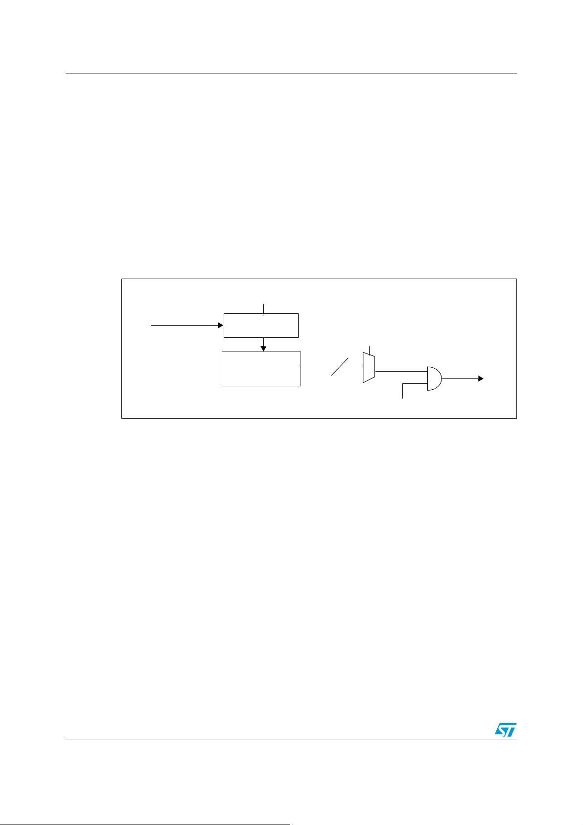
AN2780 Associated software example description
ai15324
falling edge interruptEXTI
Edge counter +1
Edge counter
> Edge counter limit ?
Return
Ye s
No
Edge limit overflow counter +1
Edge counter = 0
Figure 6. BEEP signal edge external interrupt - example of increment & compare
cycle performed on pair of registers of fx_time structure
This cycle first increments a counter. Then the counter value is compared with the
predefined limit and number of the limit overflows is stored into the next variable. It mainly
acts as a prescaler. The number of overflows is used by the main program to define the
number of time interval cycles elapsed when real-time information is processed and
real_time structure content is updated.
2.4 Application interface - real-time conversions
The two alternative methods of recalculation mentioned above are described in more details
in this section. Both methods use the information stored in the fx_time structure and convert
this time information into the real_time structure. The only difference is how often and in
which way real-time information is recalculated by main loop and how many increment &
compare cycles are performed by interrupt service. The main loop always checks the state
of overflow registers in the fx_time structure either continuously or on application request
and converts this information into the real_time structure. The result of every conversion
reflects the number of detected elapsed intervals and it is stored in the real_time structure
registers keeping seconds, minutes, hours and etc.
These methods are given as examples only. The user can modify the fx_time and/or
real_time structures. Some other recalculation methods can also be used.
One of these two methods is always selected through the definition control of the KEEP_RT
parameter as it is described in Section 2.1.2: Configuration definitions in rtc.h file.
Doc ID 14759 Rev 2 13/20
Page 14

Associated software example description AN2780
2.4.1 First alternative solution: real-time kept continuously
Keeping real-time information continuously is suitable in case the information is permanently
used by the application (e.g. actual time must be displayed or sent).
In this case, an additional increment & compare cycle is added for one-second interval
measurements into the interrupt service. The elapsed one-second intervals are then
checked in the main loop. Real-time incremental routine rt_increment() is called from the
main loop to process every new elapsed one-second interval detected by interrupt routine. It
ensures the actual real-time information is kept continuously in the real_time data structure.
Note: As a one-second increment & compare cycle is short and the beeper frequency may not
exactly match the one-second interval, a measurement error for this interval can be
relatively high (up to 0.1% when the beeper frequency is 500 Hz). The one-second time
interval is rounded to the closest integer number of beeper signal pulses. Due to this short
measurement interval, a significant error is cumulated when a longer real-time interval is
evaluated from this measurement.
Figure 7. Main loop service checking the one-second events
Main loop task keeping
real-time information
ai15325
Next one-second interval
elapsed?
No
Return
Real-time structure 1s increment
Ye s
A more accurate “real_time” data structure update calculation can also be performed in this
mode at any time, as described in the following section.
2.4.2 Second alternative solution: real-time converted on request
Converting real-time information on request is suitable for low-power systems where the
information is needed occasionally (e.g. when errors occur or in specific cases) and when
saving power is a priority. Then the interrupt service duration is reduced to a minimum and
the recalculation routine from the main loop is called only in case the information is
requested. The main loop service then calls the rt_update() conversion function only on
update request from application. This function updates the content of the user real_time
14/20 Doc ID 14759 Rev 2
Page 15

AN2780 Associated software example description
ai15326
Main loop task keeping
real-time information
Real-time structure updater
One-second event register = 0
Day overflow register = 0
Real time information
needed?
Ye s
No
Halt
data structure to the current state depending on the content of the internal counters in the
fx_time structure.
Note: Drawback: the conversion is much more complicated in this case, because a few divisions
must be performed to obtain values of the seconds, minutes and hours from the current
edge_day_counter counter content.
Advantage: the measured interval is much longer, so the calculation is more precise when
this method is used.
Figure 8. Main loop service checking the real-time update request
Doc ID 14759 Rev 2 15/20
Page 16

Firmware environment AN2780
3 Firmware environment
A complete project is included in the STM8S and STM8A firmware package. This project is
designed for the ST Visual Develop (STVD) development environment.
Two projects are contained in the associated software package: one for Cosmic compiler
and one for the Raisonance compiler. Both projects have been tested using the STM8/128EVAL evaluation board. To run the proper project example, you must have installed STVD
(at least version 3.5.0) and the Cosmic or Raisonance C compiler for STM8 family. All tools
are free for download from STMicroelectronics, Cosmic and Raisonance web sites.
Ta bl e 1 gives the list of the files included in the package.
Table 1. List of files included in the STM8S and STM8A firmware package
File name File contents
main.c RTC routines & example of how to handle them
stm8s_it.c User interrupt services
stm8s_interrupt_vector.c STM8S interrupt vector table
stm8s_awu.c Peripheral file
stm8s_beep.c Peripheral file
stm8s_clk.c Peripheral file
stm8s_exti.c Peripheral file
stm8s_gpio.c Peripheral file
stm8s_tim3.c Peripheral file
rtc.h User header file
stm8s_awu.h Peripheral header file
stm8s_beep.h Peripheral header file
stm8s_clk.h Peripheral header file
stm8s_exti.h Peripheral header file
stm8s_gpio.h Peripheral header file
stm8s_tim3.h Peripheral header file
stm8s_config.h STM8 hardware configuration header
stm8s_map.h STM8 hardware mapping header
stm8s_type.h Common data type header
stm8s_it.h Interrupt declaration header
stm8s_lib.h Library peripheral headers including control
mods0.h Memory model control header
16/20 Doc ID 14759 Rev 2
Page 17

AN2780 Test environment
4 Test environment
The functionality of the interface has been tested on STM8/128-EVAL evaluation board. The
main.c file of the included project contains simple examples of how to keep real-time
information.
● In case real-time data is kept continuously (KEEP_RT is defined), the one-second
events are checked in main loop and real-time registers are updated in intervals of one
second.
● In case real-time data is not kept continuously, real-time registers are updated only on
external interrupt service request. This simulation is performed by pressing the “Key”
button on the evaluation board. The user can check the current content of real-time
structure registers by using the STVD “Read on the fly” debug feature.
Both the BEEP output frequency and the LS clock frequency can be monitored by
connecting an oscilloscope to the BEEP pin (PD4) and CLK_CCO pin (PE0). The outputs of
these signals are enabled in the initialization phase.
Doc ID 14759 Rev 2 17/20
Page 18

Accuracy of the used method AN2780
5 Accuracy of the used method
As described in this document, the time measurement accuracy of the methods used in
these examples is mainly dependent on LSI measurement accuracy. Consequently, the user
must also take into account the fact that the LSI clock frequency varies with temperature and
voltage.
In case of a low-power application where consumption is a critical point and often no
external frequency signal is available, only the method using internal LSI measurement by
HSI frequency can be used.
When the HSI clock feeds the internal timers with a maximal rate and its value is precisely
known, the LSI value can be determined from the measurement of 8 consecutive periods
with an accuracy of 128 KHz / 16 MHz / 8 ~ 0.1% steps. This means the best theoretical
accuracy would be almost equal to 4 seconds per hour.
It is in fact difficult to determine precisely the HSI frequency without any external reference
frequency. As the HSI_VALUE constant entered as a parameter for calculation can differ
from the real HSI frequency, the LSI result accuracy is significantly reduced.
The default 16 MHz value cannot be used because there is a big tolera?nce for shipped
devices in this case (up to +1.3%/-2.5% at 5 V/25 °C, but up to +3%/-4% in a wider range of
supply voltage or temperature).
The HSI can be trimmed internally within an interval of +3/-4% of the frequency range to get
a value as near as possible to the 16 MHz nominal value.
Note that the frequency change between two trimming steps is 0.5% of the range (even 1%
in some STM8S and STM8A devices), so the difference after trimming can remain too
significant.
Much better accuracy can be achieved when the HSI frequency (and, consequently, the LSI)
can be measured and/or compared using an exact external reference frequency (e.g. by net
frequency). These comparative measurements must be performed at adequate intervals to
detect any significant temperature and power supply voltage changes so as to compensate
for them.
In addition, the LSI clock frequency also depends on temperature and supply voltage.
Temperature and voltage conditions can change this value in the similar range as the HSI in
the same conditions. That is why real-time measurement accuracy can be partly improved
by repeating periodically the LSI measurement to compensate for possible condition
changes.
Note: Finding an accurate external frequency source which can precisely state the value of
internal frequency sources is especially a problem for low-cost and battery-supplied
applications as a crystal oscillator is a rather expensive solution and battery-supplied
devices cannot have a stable net frequency that could be used as a reference.
5.1 Conclusion
The level of accuracy of real-time measurement based on LSI is only suitable for
applications working in stable conditions where real-time information is used only as an
approximate indication. It is strongly recommended to use an external low frequency signal
source or special components keeping real-time information with much better accuracy in
any other cases.
18/20 Doc ID 14759 Rev 2
Page 19

AN2780 Revision history
6 Revision history
Table 2. Revision history
Date Revision Description of changes
18-Mar-2010 1 Initial release
31-Aug-2011 2 Updated to refer to STM8S and STM8A.
Doc ID 14759 Rev 2 19/20
Page 20

AN2780
Please Read Carefully:
Information in this document is provided solely in connection with ST products. STMicroelectronics NV and its subsidiaries (“ST”) reserve the
right to make changes, corrections, modifications or improvements, to this document, and the products and services described herein at any
time, without notice.
All ST products are sold pursuant to ST’s terms and conditions of sale.
Purchasers are solely responsible for the choice, selection and use of the ST products and services described herein, and ST assumes no
liability whatsoever relating to the choice, selection or use of the ST products and services described herein.
No license, express or implied, by estoppel or otherwise, to any intellectual property rights is granted under this document. If any part of this
document refers to any third party products or services it shall not be deemed a license grant by ST for the use of such third party products
or services, or any intellectual property contained therein or considered as a warranty covering the use in any manner whatsoever of such
third party products or services or any intellectual property contained therein.
UNLESS OTHERWISE SET FORTH IN ST’S TERMS AND CONDITIONS OF SALE ST DISCLAIMS ANY EXPRESS OR IMPLIED
WARRANTY WITH RESPECT TO THE USE AND/OR SALE OF ST PRODUCTS INCLUDING WITHOUT LIMITATION IMPLIED
WARRANTIES OF MERCHANTABILITY, FITNESS FOR A PARTICULAR PURPOSE (AND THEIR EQUIVALENTS UNDER THE LAWS
OF ANY JURISDICTION), OR INFRINGEMENT OF ANY PATENT, COPYRIGHT OR OTHER INTELLECTUAL PROPERTY RIGHT.
UNLESS EXPRESSLY APPROVED IN WRITING BY TWO AUTHORIZED ST REPRESENTATIVES, ST PRODUCTS ARE NOT
RECOMMENDED, AUTHORIZED OR WARRANTED FOR USE IN MILITARY, AIR CRAFT, SPACE, LIFE SAVING, OR LIFE SUSTAINING
APPLICATIONS, NOR IN PRODUCTS OR SYSTEMS WHERE FAILURE OR MALFUNCTION MAY RESULT IN PERSONAL INJURY,
DEATH, OR SEVERE PROPERTY OR ENVIRONMENTAL DAMAGE. ST PRODUCTS WHICH ARE NOT SPECIFIED AS "AUTOMOTIVE
GRADE" MAY ONLY BE USED IN AUTOMOTIVE APPLICATIONS AT USER’S OWN RISK.
Resale of ST products with provisions different from the statements and/or technical features set forth in this document shall immediately void
any warranty granted by ST for the ST product or service described herein and shall not create or extend in any manner whatsoever, any
liability of ST.
ST and the ST logo are trademarks or registered trademarks of ST in various countries.
Information in this document supersedes and replaces all information previously supplied.
The ST logo is a registered trademark of STMicroelectronics. All other names are the property of their respective owners.
© 2011 STMicroelectronics - All rights reserved
STMicroelectronics group of companies
Australia - Belgium - Brazil - Canada - China - Czech Republic - Finland - France - Germany - Hong Kong - India - Israel - Italy - Japan -
Malaysia - Malta - Morocco - Philippines - Singapore - Spain - Sweden - Switzerland - United Kingdom - United States of America
www.st.com
20/20 Doc ID 14759 Rev 2
 Loading...