

Page 1

AN2777
Application note
New high-temperature, high-performance TRIACs for
optimized vacuum cleaner designs
Introduction
A new high-temperature TRIAC family, able to work up to a 150 °C junction temperature in
steady-state, has been introduced. This family helps to reduce the bulk of the required
heatsink. These TRIACs are particularly suitable for hot or limited environments found in
home appliances, such as vacuum cleaners.
One key parameter in the design of TRIACs operating at high temperature is the turn-off
capability. We explain here briefly how to optimize this parameter and present the
performances of a new 12 A, 600 V device.
Test results are also presented to compare these performances to other high-temperature
TRIACs available on the market today. These tests are performed in extremely severe
temperature conditions as can appear in vacuum cleaners.
April 2009 Doc ID 14748 Rev 1 1/13
www.st.com
Page 2

Contents AN2777
Contents
1 TRIAC turn-off behavior . . . . . . . . . . . . . . . . . . . . . . . . . . . . . . . . . . . . . . 3
2 Improvement of turn-off capability for new high-temperature TRIACs 6
3 Vacuum cleaner requirements . . . . . . . . . . . . . . . . . . . . . . . . . . . . . . . . . 8
3.1 Steady state thermal design . . . . . . . . . . . . . . . . . . . . . . . . . . . . . . . . . . . . 8
3.2 Inrush current . . . . . . . . . . . . . . . . . . . . . . . . . . . . . . . . . . . . . . . . . . . . . . . 9
3.3 Turn-off requirement . . . . . . . . . . . . . . . . . . . . . . . . . . . . . . . . . . . . . . . . . . 9
3.4 Jammed nozzle operation . . . . . . . . . . . . . . . . . . . . . . . . . . . . . . . . . . . . 11
4 Conclusion . . . . . . . . . . . . . . . . . . . . . . . . . . . . . . . . . . . . . . . . . . . . . . . . 12
5 References . . . . . . . . . . . . . . . . . . . . . . . . . . . . . . . . . . . . . . . . . . . . . . . . 12
6 Revision history . . . . . . . . . . . . . . . . . . . . . . . . . . . . . . . . . . . . . . . . . . . 12
2/13 Doc ID 14748 Rev 1
Page 3

AN2777 TRIAC turn-off behavior
N4
1 TRIAC turn-off behavior
When a TRIAC switches from on-state to off-state, the current passes through zero, and the
line voltage is rapidly reapplied across the structure. This voltage level is higher for inductive
loads with low power factor, such as pumps or motors. Indeed, for such loads, the phase
shift between current and voltage is high, and a voltage in the range of 50 to 200 V can be
applied for applications running on a 230 V rms line.
Under certain conditions, the component is not able to block this voltage, and so turns on
spontaneously [see References 1.] Indeed, a TRIAC can be compared to two thyristors
mounted in back-to-back association and coupled with a single control area. To trigger the
two thyristors, the control area overlaps the two conduction areas (see Figure 1).
During conduction, a certain quantity of charges is injected into the structure. These
charges disappear by recombination during current decrease, and by extraction with the
reverse recovery current after the turn-off. Figure 3 shows this recombination current with a
230 V, 50 Hz, 25 W pump (see Figure 2 for test schematics).
Figure 1. Simplified TRIAC silicon structure
A1 G
I
-
N1
P1
N4
P1
Gates
N2
P2
Ctrl
I
+
A2
N2
P2
N3
Figure 2. Simplified test schematic
Load
C
V
L
V
R
T
I
T
The recombination of the charges takes place particularly in the neighboring regions of the
gate. These charges can induce the triggering of the other conduction area when the mains
voltage is reapplied across the TRIAC. Figure 4 shows this kind of behavior with the same
load as given in Figure 3, but with a TRIAC with a lower turn-off capability.
Doc ID 14748 Rev 1 3/13
Page 4

TRIAC turn-off behavior AN2777
Figure 3. TRIAC turn-off with pump
V
Mains
(100 V/div)
VT(100 V/div)
Recovery current
IT(10 mA/div)
Figure 4. Charge recombination induces wrong TRIAC turn-on during turn-off
dV/dt
dV/dt
OFF
OFF
VT(50 V/div)
VT(50 V/div)
dI/dt
dI/dt
To characterize the TRIAC turn-off capability, semiconductor manufacturers use a circuit
where the rate of current decrease can be adjusted. In addition, the slope of the reapplied
voltage can be controlled by using a circuit of resistors and capacitors connected across the
TRIAC [see References 1.] For a given dV/dt
increase the dI/dt
(a)
to reach TRIAC spontaneous re-triggering. This is the critical point
OFF
that the TRIAC is able to withstand. The rate levels of this point are called (dI/dt)c and
4/13 Doc ID 14748 Rev 1
(dV/dt)c in TRIAC datasheets.
a. The expressions dV/dt
the load.
OFF
and dI/dt
refer to the slopes induced by the “natural” current and voltage across
OFF
OFF
OFF
IT(10 mA/div)
IT(10 mA/div)
(a)
(see Figure 4), we progressively
OFF
Page 5

AN2777 TRIAC turn-off behavior
The value of (dI/dt)c decreases if the reapplied (dV/dt)c is increasing. The value of (dI/dt)c
also strongly decreases if the junction temperature is increasing. Figure 5 gives the (dI/dt)c
relative variation according to the junction temperature for a Snubberless TRIAC from
STMicroelectronics. This device is the BTB12-600CW (12 A, 600 V, 35 mA I
). Snubberless
gt
means that the specified (dI/dt)c has been chosen so that it is guaranteed whatever the
reapplied (dV/dt)c [see References 1.] Thus there is no need to add an R-C snubber circuit
across the TRIAC to help it to turn-off [see References 2.]
Figure 5. BTB12-600CW (dI/dt)c variation with junction temperature
(dI/dt)c[Tj]/(dI/dt)
5
4
3
2
1
0
25 50 75 100 125 150
c
=125°C]
[T
j
Tj(°C)
Doc ID 14748 Rev 1 5/13
Page 6

Improvement of turn-off capability for new high-temperature TRIACs AN2777
2 Improvement of turn-off capability for new high-
temperature TRIACs
As shown previously (for example in Figure 5), (dI/dt)c drastically decreases with the die
temperature. For example, the BTB12-600CW capability would be 35% lower at 150 °C
compared to 125 °C. This 35% decrease is quite usual for all TRIACs. As dI/dt
depends on the rms load current (as given in the equation below), the TRIAC at 150 °C
would be able to drive loads with 35% lower power.
Equation 1
3
-
RMS)ms/A(OFF
π=
Of course, such a load power derating cannot be accepted. Compensating for this derating
would lead appliance designers to use a higher current TRIAC, if they wanted to increase
the working temperature. STMicroelectronics has improved the design of the device to
improve the TRIAC turn-off capability.
The following simulation indicates the results that can be obtained with the design
improvements. Figure 6 gives the simulation result of two different devices. One is able to
turn-off, the other one not.
10F22Idt/dI ····
)Hz()A(
OFF
only
Figure 6. Simulation results for two different TRIACs
IT (A)
0.3
0.2
0.1
0
9.970E-04 9.990E-04 1.001E-03 1.003E-03 1.005E-03 1.007E-03
-0.1
-0.2
-0.3
-0.4
-0.5
1 2 3
-0.6
time (s)
Improved structure
Reference structure
This breakthrough design has strongly improved device performance for high temperature
applications.
The new high-temperature TRIAC family features very high commutation capabilities. For
example, Figure 7 compares the BTB12-600CW with a new high-temperature T1235H-6
device. This figure shows that the turn-off capability is approximately four times higher with
the new device over the whole temperature range.
6/13 Doc ID 14748 Rev 1
Page 7

AN2777 Improvement of turn-off capability for new high-temperature TRIACs
Figure 7. (dI/dt)c variation versus temperature for new and old device
(dI/dt)
[Tj](A/ms)
140
120
c
100
BTB12-600CW
80
T1235-6H
60
40
20
0
25 50 75 100 125 150
T
(°C)
j
Doc ID 14748 Rev 1 7/13
Page 8

Vacuum cleaner requirements AN2777
3 Vacuum cleaner requirements
3.1 Steady state thermal design
As for all power semiconductor applications, one main point to check is the thermal design.
It has to be checked to ensure the working junction temperature is below the maximum
allowed temperature (T
For this purpose, the heatsink thermal resistance (R
dissipated power (P) and maximum ambient temperature (T
References 3.)
Equation 2
T
≤
jmax-Tamax
P
R
thHS
In vacuum cleaners an efficient way to decrease the heatsink size is to put it in the air flow.
However, it is quite difficult to evaluate the required heat-sink size. A good way to check the
thermal design is then to measure the case temperature and check if this value is lower than
the specified value (see Figure 8, from T1235H-6 datasheet). This figure shows that for a
10 A rms current, the case temperature can reach 116 °C.
j max
).
) has to be chosen according to
thHS
) (see Equation 2 and
a max
Experimental tests have been performed on a 2000 W vacuum cleaner. The maximum
dissipated power occurs for the maximum speed (delay between line zero voltage and
TRIAC turn-on is 0.75 ms, refer to Table 1 and Figure 12). The rms load current equals 10 A.
With a 20 cm² white aluminum plate (2 mm width), the case temperature reaches only
100 °C. This means that there is almost a 16 °C safety margin.
Figure 8. Maximum allowed current versus case temperature for T1235H-6
I
(A)
T(RMS)
14
12
10
8
6
4
2
TC(°C)
0
0 25 50 75 100 125 150
-TO 220AB
Insulated
TO-220AB/D²PAK
8/13 Doc ID 14748 Rev 1
Page 9

AN2777 Vacuum cleaner requirements
3.2 Inrush current
Inrush current also causes significant stress on TRIACs, especially if the motor is turned on
in full wave mode. Today, with the electromagnetic standard applied to limit light flickering
due to appliance inrush currents (IEC 61000-3-3 standard), most vacuum cleaners feature a
microcontroller which implements a soft-start function. A full-cycle start-up thus occurs only
with wrong triggering by the microcontroller.
Figure 9 gives the measured inrush current of a 2000 W motor started in full-cycle mode,
with a 264 V rms line voltage (worst case for a 220-240 V line). The inrush current can reach
up to 70 A. This level is well below the maximum peak current allowed for the T1235H-6
device (I
Figure 9 also gives the calculated junction temperature for this device in a TO220AB
insulated package. The initial device temperature is 60 °C, as it could occur in the
application if the motor has already operated before a new start-up. Dissipated power is
calculated with max V
thermal impedance taken into account is given in our datasheet (R
be seen that the junction temperature remains below 150 °C during this start-up. The
operation is then totally safe for the device.
Figure 9. Junction temperature and current at start-up (2000 W, 230 V motor,
= 120 A for a 20 ms pulse).
TSM
and Rd parameters given in our datasheet [see References 4.] The
to
T1235H-6I TRIAC)
= 3.3 °C/W). It can
th(j-c)
Current (A)
200
150
100
50
0
-50
-100
-0.05 0 0.05 0.1 0.15 0.2 0.25 0.3 0.35
3.3 Turn-off requirement
As explained above, the dI/dt
TRIACs working at high temperatures. Furthermore, universal motors impose high dI/dt
rates due to the brush commutations. Figure 10, for example, shows that the dI/dt
(➀) can be approximately 50% higher than the value due to the 50 Hz wave shape (dI/dt
➁, as defined in Equation 1).
OFF
Temperature (°C)
and
IT
Tj
time (s)
constraint is one of the main points to check, especially for
OFF
rate
OFF
OFF
Doc ID 14748 Rev 1 9/13
Page 10

Vacuum cleaner requirements AN2777
Figure 10. Turn-off constraint (2000 W - 230 V motor)
1
1
V
V
T
T
2
2
I
I
T
T
dI/dt
dI/dt
OFF
OFF
As the motor speed in vacuum cleaners is set by changing the TRIAC turn-on delay (t
the back emf varies also with this delay. The worst dI/dt
can then occur for a different
OFF
ON
),
setting than the maximum speed. Ta bl e 1 gives some measurements performed on the
same 2000 W, 230 V motor. It shows that even if the load rms current increases when the
turn-on delay decreases, dI/dt
increases. The worst case occurs then for the minimum
OFF
speed, with a 7.3 A/ms rate. Such a rate is less than half the level that the T1235H can
withstand at a 150 °C junction temperature (16 A/ms).
Figure 11. Turn-on delay definition
V
V
L
L
I
I
T
T
V
V
T
T
t
t
ON
ON
Table 1. Measurements with 2000 W, 230 V motor
tON (ms) 6 5 0.75
I
(A) 46.710
RMS
dI/dt
OFF
7.3 5.9 4.5
10/13 Doc ID 14748 Rev 1
Page 11
AN2777 Vacuum cleaner requirements
3.4 Jammed nozzle operation
For vacuum cleaners, the worst operating condition occurs when the tube is blocked. This
operation does not lead to a higher current. On the contrary, as there is no air flow anymore,
the motor torque is lower and the motor rms current can decrease down to 8 A.
In fact, the stress comes from the fact that the heatsink thermal impedance drastically
increases as there is no cooling air flow anymore. The case temperature can then reach up
to 120 or 140 °C. The TRIAC (dI/dt)c capability is then highly reduced. This can cause failed
turn-off. The motor suddenly goes from low speed to high speed with a half-cycle full
conduction mode. Such operation causes noise variation and vacuum cleaner vibration.
Appliance manufacturers try to reduce this kind of behavior as much as possible, since it
may give a poor quality image of their equipment to the end-user.
This is the reason why some closed-box tests are usually performed by vacuum cleaner
designers to check the TRIAC’s ability to withstand such a stressful operation. We have
performed such a test with the following conditions:
● TRIAC enclosed in a 10.5 x 8 x 5 cm cardboard box
● Plastic foam around the box to thermally insulate it
● 1000 W, 110 V motor to reach 17 A/ms dI/dt
● Motor rms current: 5.5 A (medium speed)
● Line voltage: 120 V, 60 Hz
● No heatsink
OFF
rate
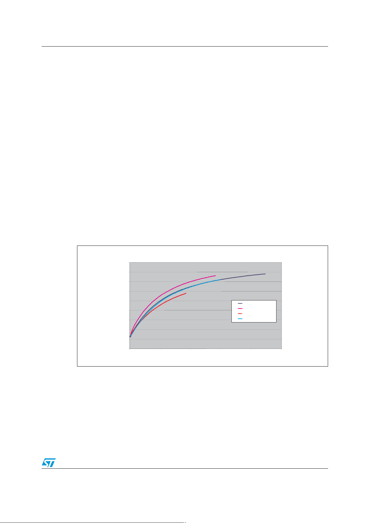
Figure 12. TRIAC performance comparison for closed-box test
Tcase (°C)
180
160
140
120
100
80
60
40
20
0
0 50 100 150 200 250
time (s)
T1235H - ST
Device A
Device B
Device C
The case temperature is measured from motor start-up to spurious TRIAC turn-off.
Figure 12 gives the results with the T1235H-6I and other 12 A, 600 V, 35 mA, 150 °C TRIAC
devices in insulated packages. Device A case temperature increases faster than all other
devices. This means that its power losses are higher than the other devices. This could be
certainly due to a smaller die size. Device B heating time is the slowest. But this device is
only able to withstand the dI/dt
rate up to a 116 °C case temperature, whereas the
OFF
T1235H works up to 156 °C. Device C presents the same power losses as the T1235H but
works well only up to 144 °C.
Using a T1235H device thus helps to withstand the closed-box test by more than 1 mn
beyond the other devices.
Doc ID 14748 Rev 1 11/13
Page 12

Conclusion AN2777
4 Conclusion
An innovative high-temperature TRIAC family has been presented. The turn-off capability of
this family of devices is four times higher than previous Snubberless devices. The
performances of a 12 A device have been presented. The turn-off performances have been
specially improved and are far higher than other devices available today.
Such technology can be used to optimize vacuum cleaner design. It has been shown that
such a 12 A device can be used in 2000 W, 230 V vacuum cleaners, whereas 16 A or 25 A
devices were commonly used in the past. This allows the power board price to be reduced.
As these devices are working up to a 150 °C junction temperature, the heatsink size can
also be reduced, leading to another cost reduction.
And above all, the performances of these devices also allow the end-product quality to be
increased. Indeed, time before bad operation can be increased by 50% during jammed
nozzle operation.
5 References
1. “TRIAC turn-off behavior, logic level and Snubberless technologies”, Application Note
AN489, STMicroelectronics.
2. “RC snubber circuit design”, Application Note AN437, STMicroelectronics.
3. “SCRs, TRIACs and AC switches: thermal management precautions for handling and
mounting”, Application Note AN533, STMicroelectronics.
4. “T1235H, T1250H, High Temperature 12 A TRIACs”, datasheet, STMicroelectronics.
6 Revision history
Table 2. Document revision history
Date Revision Changes
24-Apr-2009 1 Initial release.
12/13 Doc ID 14748 Rev 1
Page 13

AN2777
Please Read Carefully:
Information in this document is provided solely in connection with ST products. STMicroelectronics NV and its subsidiaries (“ST”) reserve the
right to make changes, corrections, modifications or improvements, to this document, and the products and services described herein at any
time, without notice.
All ST products are sold pursuant to ST’s terms and conditions of sale.
Purchasers are solely responsible for the choice, selection and use of the ST products and services described herein, and ST assumes no
liability whatsoever relating to the choice, selection or use of the ST products and services described herein.
No license, express or implied, by estoppel or otherwise, to any intellectual property rights is granted under this document. If any part of this
document refers to any third party products or services it shall not be deemed a license grant by ST for the use of such third party products
or services, or any intellectual property contained therein or considered as a warranty covering the use in any manner whatsoever of such
third party products or services or any intellectual property contained therein.
UNLESS OTHERWISE SET FORTH IN ST’S TERMS AND CONDITIONS OF SALE ST DISCLAIMS ANY EXPRESS OR IMPLIED
WARRANTY WITH RESPECT TO THE USE AND/OR SALE OF ST PRODUCTS INCLUDING WITHOUT LIMITATION IMPLIED
WARRANTIES OF MERCHANTABILITY, FITNESS FOR A PARTICULAR PURPOSE (AND THEIR EQUIVALENTS UNDER THE LAWS
OF ANY JURISDICTION), OR INFRINGEMENT OF ANY PATENT, COPYRIGHT OR OTHER INTELLECTUAL PROPERTY RIGHT.
UNLESS EXPRESSLY APPROVED IN WRITING BY AN AUTHORIZED ST REPRESENTATIVE, ST PRODUCTS ARE NOT
RECOMMENDED, AUTHORIZED OR WARRANTED FOR USE IN MILITARY, AIR CRAFT, SPACE, LIFE SAVING, OR LIFE SUSTAINING
APPLICATIONS, NOR IN PRODUCTS OR SYSTEMS WHERE FAILURE OR MALFUNCTION MAY RESULT IN PERSONAL INJURY,
DEATH, OR SEVERE PROPERTY OR ENVIRONMENTAL DAMAGE. ST PRODUCTS WHICH ARE NOT SPECIFIED AS "AUTOMOTIVE
GRADE" MAY ONLY BE USED IN AUTOMOTIVE APPLICATIONS AT USER’S OWN RISK.
Resale of ST products with provisions different from the statements and/or technical features set forth in this document shall immediately void
any warranty granted by ST for the ST product or service described herein and shall not create or extend in any manner whatsoever, any
liability of ST.
ST and the ST logo are trademarks or registered trademarks of ST in various countries.
Information in this document supersedes and replaces all information previously supplied.
The ST logo is a registered trademark of STMicroelectronics. All other names are the property of their respective owners.
© 2009 STMicroelectronics - All rights reserved
Australia - Belgium - Brazil - Canada - China - Czech Republic - Finland - France - Germany - Hong Kong - India - Israel - Italy - Japan -
STMicroelectronics group of companies
Malaysia - Malta - Morocco - Philippines - Singapore - Spain - Sweden - Switzerland - United Kingdom - United States of America
www.st.com
Doc ID 14748 Rev 1 13/13
 Loading...