


AN2691
Application note
ST10 RPD pin:
functionality during reset and Power Down mode
Introduction
RPD is a dedicated timing pin for the return-from-power-down circuit. Additionally, when this
pin is recognized low, a reset event is taken as asynchronous. This application note gives
advice on configuring the external circuitry connected to the RPD pin in order to make it
work properly.
The information contained in this document is valid for ST10F27x and ST10R27x.
March 2008 Rev 1 1/10
www.st.com
RPD functionality AN2691
1 RPD functionality
RPD is a dual-purpose dedicated pin. This section covers its functionality.
1.1 System reset and startup
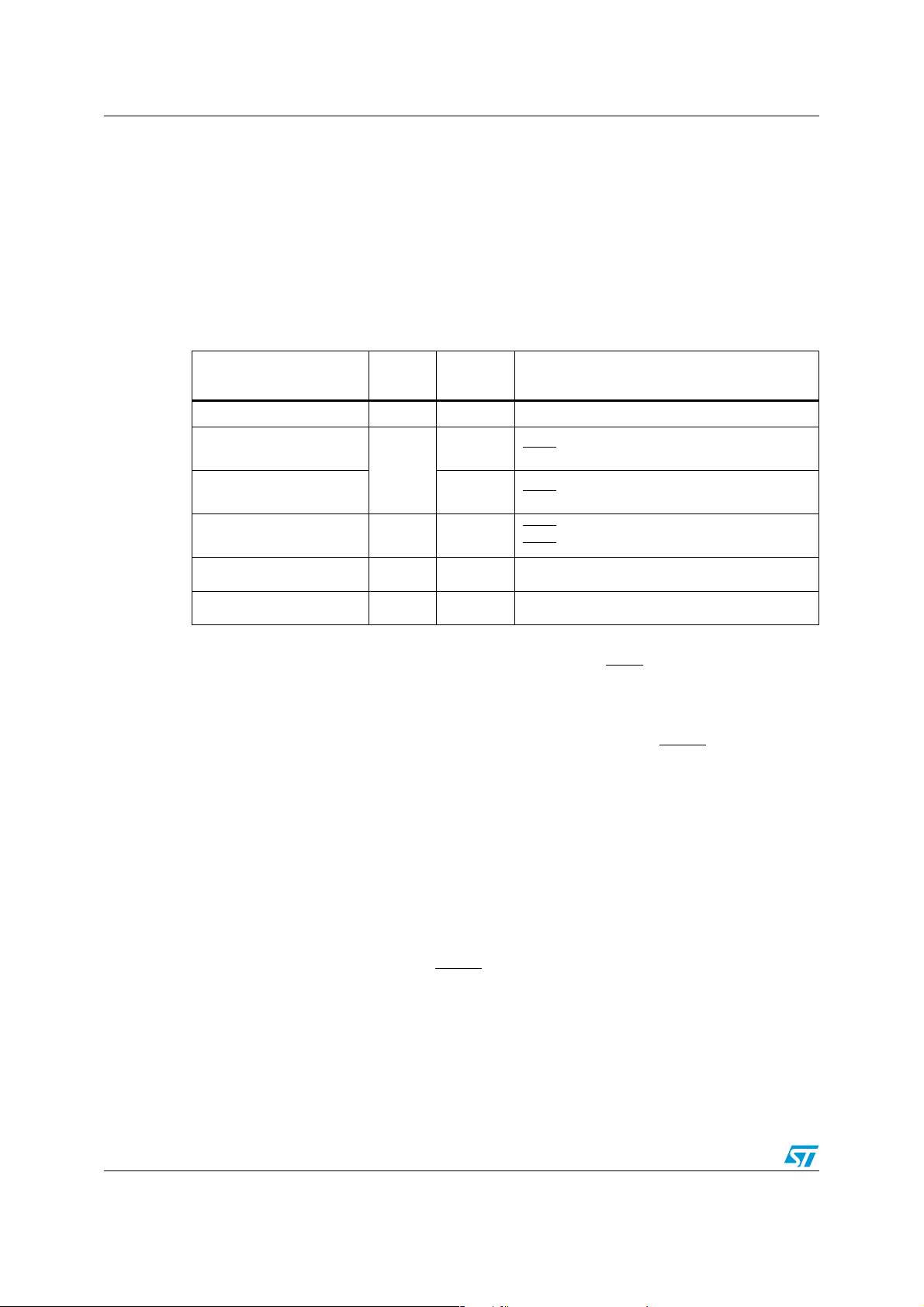
Several ST10 reset events that may occur are summarized in the following table:
Table 1. Reset event definition
Reset Source Flag
Power-on reset PONR Low Power-on
Asynchronous hardware
reset
Synchronous long
hardware reset
Synchronous short
hardware reset
Watchdog timer reset WDTR
Software reset SWR
1. Flags can be read in the WDTCON register
2. The RPD status has no influence unless bidirectional reset is activated (bit BDRSTEN in SYSCON): RPD
low inhibits the bidirectional reset on SW and WDT reset events, that is RSTIN
(1)
LHWR
SHWR High
RPD
Status
Low t
High t
(2)
(2)
Conditions
> 500 ns
RSTIN
> (1032 + 12) TCL + max (4 TCL, 500 ns)
RSTIN
t
> max (4 TCL, 500 ns)
RSTIN
t
≤ (1032 + 12) TCL + max (4 TCL, 500 ns)
RSTIN
WDT overflow
SRST instruction execution
is not activated.
Therefore, roughly, the RPD pin level distinguishes between an asynchronous (low level)
and a synchronous reset (high level). The main difference between these two kinds of reset
is that the first immediately cancels pending internal hold states and if any, it aborts all
internal/external bus cycles whereas in the synchronous reset, after RSTIN
level is
detected, a short duration of a maximum of 12 TCL (six periods of CPU clock) elapses,
during which pending internal hold states are cancelled and the current internal access
cycle, if any, is completed. For this reason, if an asynchronous reset occurs during a read or
write phase in internal memories, the content of the memory itself could be corrupted. To
avoid this, synchronous reset usage is strongly recommended.
However, asynchronous reset must be used during the power-on of the device. Depending
on crystal or resonator frequency, the on-chip oscillator needs about 1 ms to 10 ms to
stabilize with an already stable V
. The logic of the ST10 does not need a stabilized clock
DD
signal to detect an asynchronous reset and is therefore suitable for power-on conditions.
On the contrary, the reset state machine needs a stabilized clock to operate correctly.
According to the length of pulse on RSTIN
long or short. Long and Short synchronous resets differ by the start-up configuration bits
latched:
– Long synchronous reset latches the entire Port0 configuration, including clock
frequency selection (P0[15:13])
– Short synchronous reset ignores the bits P0[15:13] and the same clock frequency
is applied.
2/10
, the synchronous reset may be recognized as
AN2691 RPD functionality
Refer to the product documentation for a full description of the reset mechanism.
The RSTIN
pin is an input of the device that can be configured as an output that shows a
low level during the internal reset condition. This is called bidirectional reset and is enabled
by setting the BDRSTEN bit in the SYSCON register.
When enabled, the open drain of the RSTIN
pin is activated, pulling down the reset signal
for the duration of the internal reset sequence (synchronous/asynchronous hardware,
synchronous software and synchronous watchdog timer resets). At the end of the internal
reset sequence (1024 TCL) the pull-down is released.
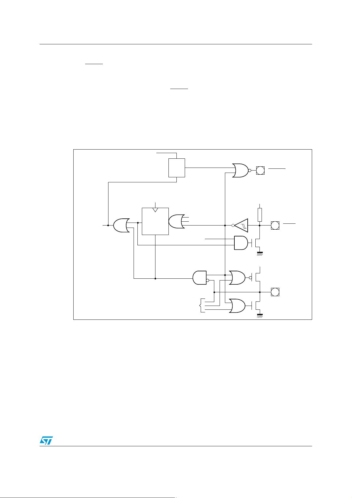
The figure below shows a simplified reset circuitry scheme.
Please refer to the product user
manual for more details and timings related to system reset.
Figure 1. Internal (simplified) reset circuitry
EINIT instruction
Clr
Internal
reset
signal
Reset state
machine
Clock
Trigger
Clr
Q
Set
SRST instruction
watchdog overflow
Reset sequence
(512 CPU clock cycles)
BDRSTEN
V
RSTOUT
DD
RSTIN
Asynchronous
reset
From/to exit
powerdown
circuit
V
DD
Weak pull-down
(–200 µA)
RPD
3/10
 Loading...