

Page 1

AN2680
Application note
Fan speed controller based on STDS75 or STLM75 digital
temperature sensor and ST72651AR6 MCU
Introduction
This application note describes the method of defining the system for regulating the speed
of the 5 Vdc fan using an ST72651AR6 microcontroller and digital temperature sensor
STDS75 or STLM75.
The sensor measures the temperature data and communicates this data to the
microcontroller. Based on this temperature data, the microcontroller issues a PWM signal
with varying duty cycle to the fan for regulating its speed.
The key features of the system are:
● Microcontroller with I
and for regulating the fan speed
● Digital temperature sensor to measure the ambient temperature
● 5 Vdc fan to show the speed regulation
Section 1 highlights the features of the STDS75 or STLM75 sensor and explains its
interfacing with the microcontroller. Section 2 explains BLDC fan management and PWM
signal control to regulate the fan speed. Section 3 focuses on the hardware setup and in
Section 4 the application flow of the system is defined.
2
C interface and PWM peripheral to communicate with the sensor
February 2008 Rev 1 1/15
www.st.com
Page 2

Contents AN2680
Contents
1 Digital temperature sensor . . . . . . . . . . . . . . . . . . . . . . . . . . . . . . . . . . . . 3
1.1 Theory of operation . . . . . . . . . . . . . . . . . . . . . . . . . . . . . . . . . . . . . . . . . . 3
1.2 Interfacing of sensor with the microcontroller . . . . . . . . . . . . . . . . . . . . . . . 4
1.3 Configuring the sensor . . . . . . . . . . . . . . . . . . . . . . . . . . . . . . . . . . . . . . . . 4
1.4 Alarm signal behavior . . . . . . . . . . . . . . . . . . . . . . . . . . . . . . . . . . . . . . . . . 4
2 BLDC fan . . . . . . . . . . . . . . . . . . . . . . . . . . . . . . . . . . . . . . . . . . . . . . . . . . 5
2.1 Principle used for fan speed control using PWM . . . . . . . . . . . . . . . . . . . . 5
2.2 Method of fan speed control using a power MOSFET . . . . . . . . . . . . . . . . 5
2.2.1 PWM control using transistor at low side drive . . . . . . . . . . . . . . . . . . . . 5
3 Hardware setup . . . . . . . . . . . . . . . . . . . . . . . . . . . . . . . . . . . . . . . . . . . . . 7
3.1 Description of the hardware setup . . . . . . . . . . . . . . . . . . . . . . . . . . . . . . . 7
3.1.1 Sensor - microcontroller connection . . . . . . . . . . . . . . . . . . . . . . . . . . . . 8
3.1.2 Microcontroller - fan connection . . . . . . . . . . . . . . . . . . . . . . . . . . . . . . . . 8
4 Software flow . . . . . . . . . . . . . . . . . . . . . . . . . . . . . . . . . . . . . . . . . . . . . . . 9
4.1 Description of fan control logic . . . . . . . . . . . . . . . . . . . . . . . . . . . . . . . . . . 9
4.2 Description of alarm control logic . . . . . . . . . . . . . . . . . . . . . . . . . . . . . . . 11
5 Firmware . . . . . . . . . . . . . . . . . . . . . . . . . . . . . . . . . . . . . . . . . . . . . . . . . 12
6 References . . . . . . . . . . . . . . . . . . . . . . . . . . . . . . . . . . . . . . . . . . . . . . . . 13
7 Revision history . . . . . . . . . . . . . . . . . . . . . . . . . . . . . . . . . . . . . . . . . . . 14
2/15
Page 3
AN2680 Digital temperature sensor
1 Digital temperature sensor
The STDS75 and STLM75 are digital temperature sensors that measure the ambient
temperature and give the digital output. Both the STDS75 and STLM75 are 8-pin ICs
available in two packages , SO-8 and TSSOP-8. The measurable temperature range of the
sensors is -55 °C to 125 °C.
The STLM75 and STDS75 differ o nly in terms of the resolution of the temper ature da ta. The
STLM75 has a fixed 9-bit resolution whereas the STDS75 has configurable resolution
starting from 9 to 12 bits. In the present application, we move with the default resolution
settings of the sensor that is 9 bits a nd thus both t he STDS75 a nd STLM 75 ar e dealt with in
the same manner.
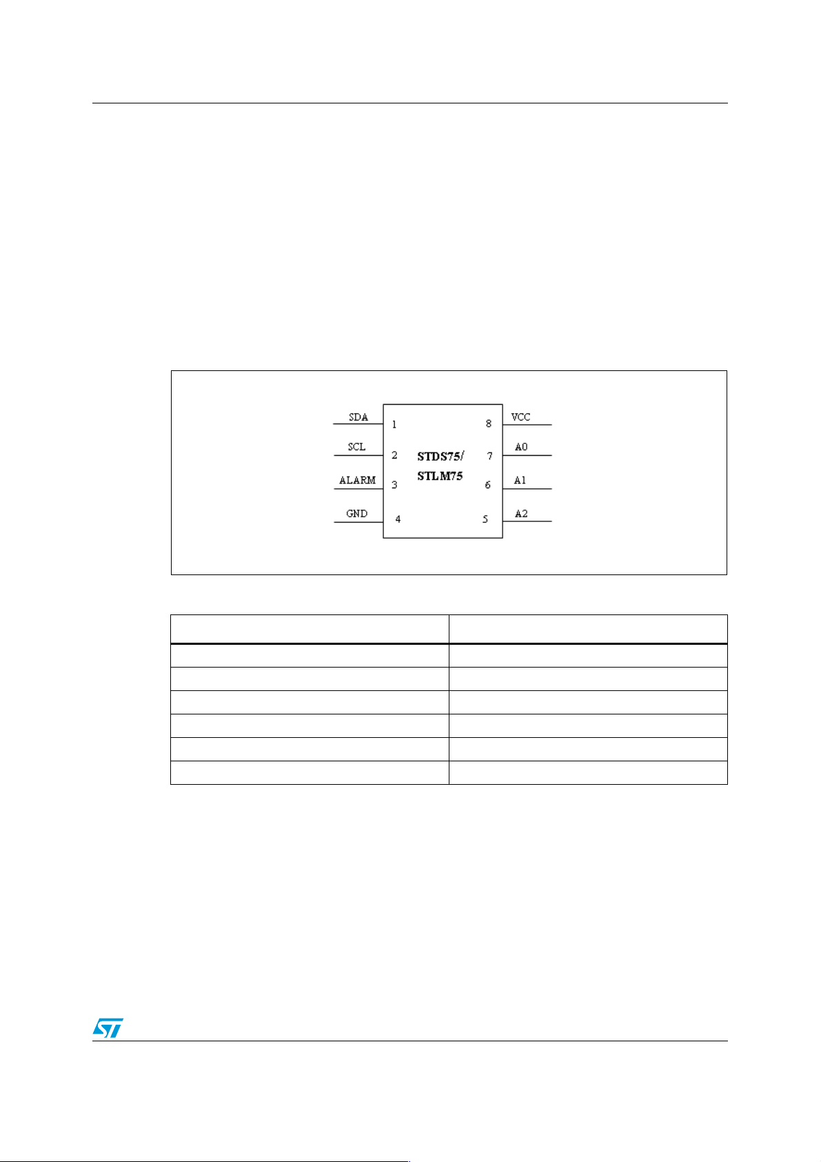
Figure 1. Temperature sensor pin description
Table 1. Pin description
Name Description
SDA Serial data input output pin
SCL Serial clock input pin
Alarm Alarm output pin
GND DC ground
A0,A1,A2 Address lines
VCC Supply voltage (2.7 V- 5.5 V)
1.1 Theory of operation
This temperature sensor is a high-precision CMOS IC with a delta-sigma analog-to-digital
converter (ADC) and I
converts the measured temperature to a digital value that is calibrated in degree Celsius.
Negative temperature is shown in two's compliment form. The sensor also has an alarm
output signal.
2
C compatible serial digital interface. The on board delta-sigma ADC
3/15
Page 4

Digital temperature sensor AN2680
1.2 Interfacing of sensor with the microcontroller
The sensor supports the I2C communication protocol. It has 3 configurable address lines,
thus can support up to 8 different addresses. All 3 address lines are g rounded in the present
application and hence the address of sensor is made 0x90.
The sensor is connected to the microcontroller through 2 communication lines of I
interface (SDA and SCL).
2
C
1.3 Configuring the sensor
The sensor has 3 internal registers which are used to configure its behavior:
1. Configuration register: Tconfig (8-bit)
2. Oversaturation register: T
3. Hysteresis register: Thys (16-bit)
Based on the value configured in the configuration register the behavior of sensor is
achiev ed. In our application these settings are made as 0x40. This setting configures the
mode of operation of the sensor and the nature of the output alarm signal. For details,
please refer to the STDS75 datasheet.
The value set in the ov ersatur ation register defin es the threshold valu e at which fan starts. In
our application the fan starts as the temperature rises above 29 degrees Celsius. Thus the
setting for this register is made as 0x1D00. Also as the temperature rises above this
oversaturation value the alarm signal turns ON. This alarm is shown as an LED in the
system.
(16-bit)
os
A setting in the hysteresis register is used to control the output of the alarm output signal of
sensor. It is set at 27 degrees Celsius in our application which means that as the
temperature fa lls below 27 degrees Celsius the alarm goes OFF. Thus the settings for this
register are made 0x1B00.
1.4 Alarm signal behavior
The alarm signal of the sensor is configured to go ON when the measured temperature
exceeds 29 degrees Celsiu s and goes OFF when the temperature falls below 27 degrees
Celsius.
4/15
Page 5

AN2680 BLDC fan
2 BLDC fan
The basic DC brushless fan is a 2-wire de vice ov er which a DC voltage is app lied. Brushless
DC fans are called "brushless" because the electric motor is commutated electronically.
The basic brushless DC motor consists of two main parts:
a) the rotor
b) the stator
a) Rotor: As the name implies, the roto r is the pa rt that rotates. The rot or house s the
permanent magnets, and in the case of the fan, the f an bl ades are also attached to
the rotor. The number of poles in the permanent magnet varies according to the
characteristics of the motor.
b) Stator: The stator is the stationary part of the motor. It consist s of the motor coil
number which varies according to the characteristics of the motor. The stator for
the 2-phase motor consists of four coils.
2.1 Principle used for fan speed control using PWM
The speed of the DC fan can be modi fied by varying the DC voltage across the two
terminals of the fan motor. However if we t ak e a DC fan and switch on the DC supply across
it, the fan motor takes some time to speed up.This is because the fan motor has an inductive
coil so it does not respond immediately to the applied voltage. If we switch the power off
before the motor reaches full speed, the motor starts to slow down. If we switch the power
on and off quickly enough the fan motor and hence the fan run at some speed between the
zero and full speed. This is what is achie v ed th rough the PWM signal. The fan speed can be
modified with the variation in the duty cycle of the PWM signal.
2.2 Method of fan speed control using a power MOSFET
To control the speed of the DC fan using the PWM signal, we need to use a switch which
can be switched on and off at PWM frequency and hence control the supply voltage across
the motor of the DC fan. This switch can be made by using a high switching speed power
MOSFET. The action of switch is to connect and disconnect the power across the fan at
PWM frequency.
2.2.1 PWM control using transistor at low side drive
In low side drive connection, the fan positive terminal is kept at constant DC voltage (5 V for
5 V fan) while the negative terminal of the fan is connected to th e drain of power MOSFET.
The source of the power MOSFET is conne cted to ground . The PWM signal is applied to the
gate terminal of the power MOSFET, thus the power MOSFET switches be t w ee n o n a nd off
condition at the rate of the PWM signal. When the power MOSFET is ON, the current builds
up in the coil of the fan motor and the fan starts to attain speed, whereas when the power
MOSFET is off, the fan starts losing speed. Figure 2 illustrates the low side drive transistor.
5/15
Page 6

BLDC fan AN2680
Figure 2. Low side drive circuit
LOW SIDE DRIVE
5 Volt DC
DC
Fan
PWM
Drive
Signal
N-MOSFET
The speed of the DC fan can be regula ted b y the PWM driv e signal that chang es the supply
across the DC fan. So, varying the duty cycle of this PWM signal modifies the fan speed. At
100% duty cycle the fan runs at full speed.
6/15
Page 7

AN2680 Hardware setup
3 Hardware setup
This system consists of an ST72651AR6 microcontroller, STDS75 or STLM75 temperature
sensor, 5 V BLDC fan, N-channel power MOSFET and an alarm LED. The power to the
system is provided through USB power. Figure3 shows the setup for the system.
Figure 3. Connection diagram of the system
VCC
5 Volts
10 k
GND
NMOS
FAN
VCC
1k
MCU
PWM
I2C
Note: 1 Temperature sensor STDS75/STLM75
3.1 Description of the hardware setup
The complete system is shown in Figure 3 with the temperature sensor and f an con trol logic.
SDA
SCL
LED
10 k
I2C
ALARM
GND
VCC
TS
(1)
A0
A1
A2
Major components used in the system are:
● Microcontroller: ST72651AR6
● BLDC fan: 5 V
● Temperature sensor: STDS75
● N-Channel power MOSFET: STB100NF03L
For this application we can a lso choose any other microcontroller having a PWM peripheral
2
and I
C interface.
7/15
Page 8

Hardware setup AN2680
3.1.1 Sensor - microcontroller connection
The sensor is connected to the microcontroller using two communication lines of I2C
interface (SDA and SCL). The address lines of the sensor are grounded so that the address
of the sensor is hardwired to 0x90 (refer to the STDS75 datasheet for details). An LED is
connected to the alarm output of the sensor to show the ala rm signal. P ow er to the senso r is
provided through the 5 V USB power. A pull resistor of 10 kΩ is connected to the SDA and
SCL line of the I
2
C interface.
3.1.2 Microcontroller - fan connection
Fan control is ach ie v ed thro ugh the MOSFET switching action due to PWM signal coming to
its gate terminal. An N-channel MOSFET is used in the low side driving of the fan. The
positive terminal of the fan is connected to t he 5 V pow er supply and the negativ e terminal of
the fan is connected to th e drain of the MOSFET. The source of the MOSFET is grounded
while the gate is driven by the PWM output of the microcontroller. Current limiting resistors
are connected to the gate ter m ina ls of th e MO SF ET.
8/15
Page 9

AN2680 Software flow
4 Software flow
The software architecture of the system demonstra tes the flow of co ntrol of the f an speed on
the basis of digital temperature sensed. Figure 4 shows the flow chart of the MCU firmware
for the system.
Figure 4. Software flow diagram for fan control
Power up the system
Initialize the I2C
communication
Configure the Temperature
Sensor Device
Measure the temperature
Switch ON the Fan and
ramp up the speed with
No
(T)
T > = Tos
Yes
temperature
T > = Tmax
Yes
Run Fan at maximum
Speed
4.1 Description of fan control logic
For fan control logic, the microcontroller monitors the temperature continuously and
changes accordingly the duty cycle of the PWM output signal controlling the fan.
Switch of the Fan
No
Firstly the system is initialized and temperature is measured. This measured temperature is
compared with the threshold value (T
) set in the oversaturation register (29 degrees
os
Celsius). If the measured temperature is greate r than this v alue, then the f an is s witched ON
and the temperature is monitored again. The dut y cycle of t he PWM signa l is chang ed from
9/15
Page 10

Software flow AN2680
0 to 100% as the measured temperat ure increases from Tos to T
max
. T
is the value of the
max
temperature set through the firmware at which the fan runs at maximum speed.
Thus to control the duty cycle of the PWM signal a linear relationship is establish ed between
the measured temperature and t he duty cycle of PWM. As the measur ed temperature ramps
up, the duty cycle is also moved towards 100%.
The linear relationship with temperature is controlled by the following conditions:
● Temperature < threshold value; duty cycle is made 0% and thus fan is OFF.
● Threshold value <Temperature < T
value; duty cycle is ramped linearly towards
max
100%, thus fan runs at variable speed.
● Temperature> T
value; duty cycle is made 100%, thus fan runs at maximum speed.
max
The duty cycle is handled by writing in the registers of the PWM peripheral of the
microcontroller.
Figure 5. Software flow diagram for alarm control
Power up the system
Initialize the I2C
communication
Configure the Temperature
Sensor Device
Measure the temperature
Measure the temperature
NO
(T)
Is
T >= Tos?
YES
Alarm LED
ON
(T)
Is
T <= Thys?
YES
Alarm LED
OFF
NO
NO
Is Alarm
LED ON?
YES
10/15
Page 11

AN2680 Software flow
4.2 Description of alarm control logic
Tos is the temperature setting put in the oversatura tion register and Thys is the temperature
setting put in the hysteresis reg ister. In our app lication these values are:
● T
● Thys = 0x1B00 (27 degrees Celsius)
● T
The temperature measurement is put in continuous loop. As the measured temperature
rises above T
below the Thys value for first time.
Thus alarm behavior for measured temperature (T):
● T >= T
● Thys < T < T
● T<= Thys; alarm OFF
= 0x1D00 (29 degrees Celsius)
os
= 40 degrees Celsius
max
for the first ti me the alarm goes ON. It rem ains ON until the temperatur e f alls
os
; alarm ON
os
; alarm ON
os
11/15
Page 12

Firmware AN2680
5 Firmware
All the source files are in 'C' language and the application uses ST7 firmware library
functions.
The source files are only for guidance. STMicroelectronics shall not be liable for any direct,
indirect or consequential damages with respec t to any claim arising from use of this
software.
12/15
Page 13

AN2680 References
6 References
1. ST72651AR6 microcontroller datasheet
2. STDS75 temperature sensor datasheet
3. STLM75 temperature sensor datasheet
4. STB100NF03L power MOSFET datasheet
5. ST7 software manual user library
13/15
Page 14

Revision history AN2680
7 Revision history
Table 2. Document revision history
Date Revision Changes
06-Feb-2008 1 Initial release
14/15
Page 15

AN2680
Please Read Carefully:
Information in this document is provided solely in connection with ST products. STMicroelectronics NV and its subsidiaries (“ST”) reserve the
right to make changes, corrections, modifications or improvements, to this document, and the products and services described herein at any
time, without notice.
All ST products are sold pursuant to ST’s terms and conditions of sal e.
Purchasers are solely res ponsibl e fo r the c hoic e, se lecti on an d use o f the S T prod ucts and s ervi ces d escr ibed he rein , and ST as sumes no
liability whatsoever relati ng to the choice, selection or use of the ST products and services de scribed herein.
No license, express or implied, by estoppel or otherwise, to any intellectual property rights is granted under this document. If any part of this
document refers to any third pa rty p ro duc ts or se rv ices it sh all n ot be deem ed a lice ns e gr ant by ST fo r t he use of su ch thi r d party products
or services, or any intellectua l property c ontained the rein or consi dered as a warr anty coverin g the use in any manner whats oever of suc h
third party products or servi ces or any intellectual property contained therein.
UNLESS OTHERWISE SET FORTH IN ST’S TERMS AND CONDITIONS OF SALE ST DISCLAIMS ANY EXPRESS OR IMPLIED
WARRANTY WITH RESPECT TO THE USE AND/OR SALE OF ST PRODUCTS INCLUDING WITHOUT LIMITATION IMPLIED
WARRANTIES OF MERCHANTABILITY, FITNESS FOR A PARTICUL AR PURPOS E (AND THEIR EQUIVALE NTS UNDER THE LAWS
OF ANY JURISDICTION), OR INFRINGEMENT OF ANY PATENT, COPYRIGHT OR OTHER INTELLECTUAL PROPERTY RIGHT.
UNLESS EXPRESSLY APPROVED IN WRITING BY AN AUTHORIZED ST REPRESENTATIVE, ST PRODUCTS ARE NOT
RECOMMENDED, AUTHORIZED OR WARRANTED FOR USE IN MILITARY, AIR CRAFT, SPACE, LIFE SAVING, OR LIFE SUSTAINING
APPLICATIONS, NOR IN PRODUCTS OR SYSTEMS WHERE FAILURE OR MALFUNCTION MAY RESULT IN PERSONAL INJ URY,
DEATH, OR SEVERE PROPERTY OR ENVIRONMENTAL DAMAGE. ST PRODUCTS WHICH ARE NOT SPECIFIED AS "AUTOMOTIVE
GRADE" MAY ONLY BE USED IN AUTOMOTIVE APPLICATIONS AT USER’S OWN RISK.
Resale of ST products with provisions different from the statements and/or technical features set forth in this document shall immediately void
any warranty granted by ST fo r the ST pro duct or serv ice describe d herein and shall not cr eate or exten d in any manne r whatsoever , any
liability of ST.
ST and the ST logo are trademarks or registered trademarks of ST in various countries.
Information in this document su persedes and replaces all info rmation previously supplied .
The ST logo is a registered trademark of STMicroelectronics. All other names are the property of their respective owners.
© 2008 STMicroelectronics - All rights reserved
STMicroelectronics group of compan ie s
Australia - Belgium - Brazil - Canada - China - Czech Republic - Finland - France - Germany - Hong Kong - India - Israel - Italy - Japan -
Malaysia - Malta - Morocco - Singapore - Spain - Sweden - Switzerland - United Kingdom - United States of America
www.st.com
15/15
 Loading...