

Page 1
AN2678
Application note
Extremely accurate timekeeping over
temperature using adaptive calibration
Introduction
Typical real-time clocks use common 32,768 Hz watch crystals. These are readily available
and relatively inexpensive, but they suffer a loss of accuracy when operated over wide
temperature ranges. However, the ultra-low power characteristics of 32 KHz oscillators
make them ideal, and necessary, for battery backed applications.
Conversely, the higher speed, AT-cut crystals used with microprocessors have low drift over
a wide temperature range, and can thus provide high accuracy, but their oscillators are not
suitable for backup since they will draw much more current at the frequencies common with
AT-cut crystals.
The purpose of this application note is to show how, using a combination of these crystal
characteristics, users can get high accuracy over a wide temperature range using ST's
M41T82-83-93 series of RTCs. This is accomplished by first measuring the frequency and
then using both the analog and digital calibration features of these devices.
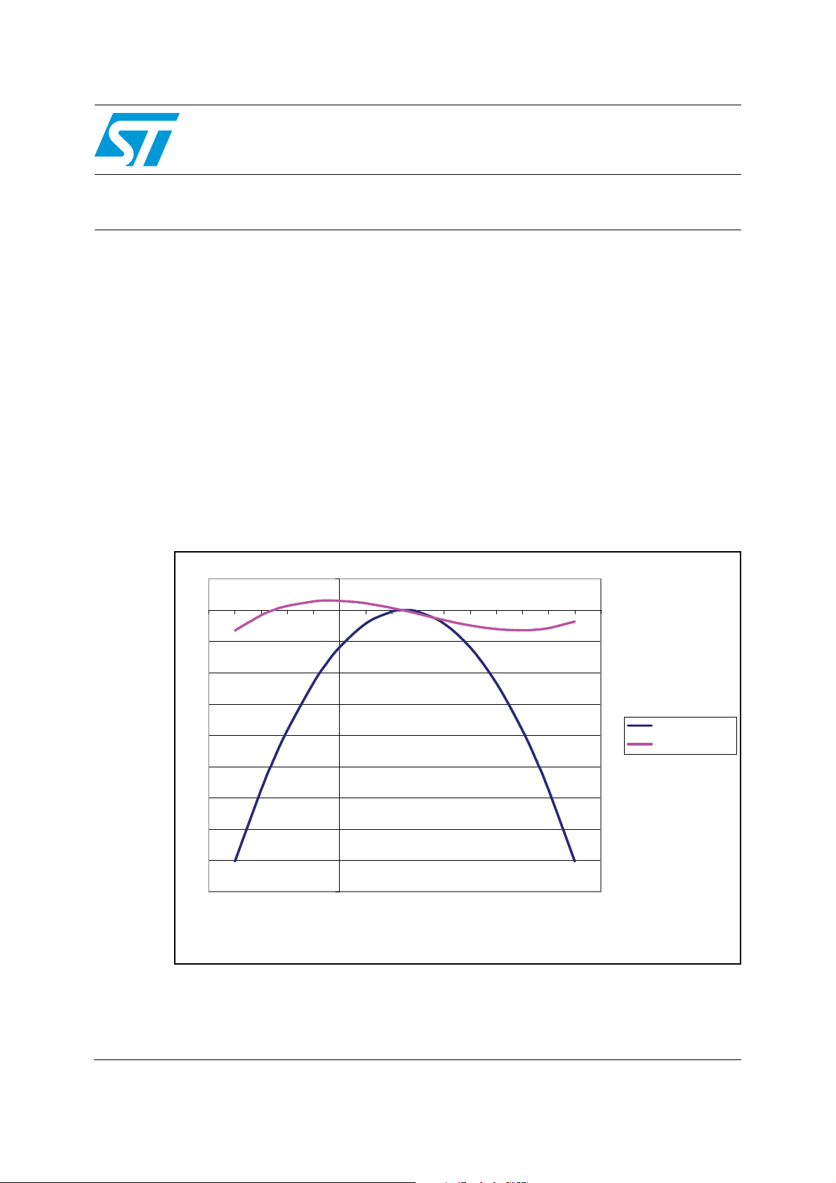
Figure 1. AT versus watch crystal - typical characteristics
20
0
-50 -40 -30 -20 -10 0 10 20 30 40 50 60 70 80 90 100
PPM
-20
-40
-60
-80
-100
-120
-140
-160
-180
TEMP (˚C)
Watch crystal
AT cut crystal
ai13944
November 2008 Rev 2 1/16
www.st.com
Page 2

M41T82-83-93 series RTCs AN2678
1 M41T82-83-93 series RTCs
ST has long offered RTCs with digital calibration, and the new M41T82-83-93 series follows
suit. In addition to digital calibration utilizing periodic counter correction, this new series
features analog calibration wherein the oscillator frequency can be adjusted by adding or
removing load capacitance via a programmable capacitance array. Analog calibration has
the added benefit of instantaneous feedback for the user; adjustments to the oscillator
speed are immediately visible in the 512 Hz test output signal built into the devices.
1.1 Oscillator temperature characteristics
As shown in Figure 1, the frequency error of typical 32 KHz oscillators is around –25 parts
per million (ppm) at both 0°C and 50°C. That is, at 25° above and below room temperature,
the device exhibits a frequency deviation of –25 ppm, and it only gets worse as the
temperature deviates farther from +/–25°C.
Conversely, for an AT cut crystal, as is commonly used with microprocessors, the frequency
deviation is much less pronounced over a wide range of temperatures. The trade-off is that
AT cut crystals usually operate at frequencies much, much higher than watch crystals and
thus require much more power - too much for battery backup as is typically employed with
real-time clocks (RTCs).
But it is possible to get the low power performance of watch crystals along with the wide
temperature accuracy of AT cut crystals if the RTC can be periodically calibrated by the
microprocessor, almost all of which nowadays include timers that can be employed to
measure the frequency test (FT) pin of the RTC and correct any error in the timing utilizing
the calibration features of the RTC.
The approach discussed herein utilizes both of the calibration circuits in ST's M41T82,
M41T83 and M41T93 serial RTCs. This application note describes how to perform an initial
calibration, using the analog circuit, followed by occasional calibration updates using the
digital calibration circuit.
Initially, the analog calibration circuit is adjusted at room temperature, in a closed loop
fashion wherein successively smaller and smaller adjustments are made until the error is
minimized. After that, during normal operation, the microprocessor will periodically measure
the error as before, then use a look-up table, and write adjustments to the digital calibration
circuit.
1.2 Frequency test output
In the case of ST's M41T82, M41T83 and M41T93 serial RTCs, the frequency test signal is
output on the IRQ
the M41T82 and M41T83. (Refer to the datasheets for more information and for the
M41T93 details.) The FT signal is measured by test equipment and/or the microprocessor.
The calibration circuits are then adjusted accordingly.
/FT/OUT pin. It is enabled by setting the FT bit (bit 6, register 0x08) to 1 in
The frequency test signal is nominally 512 Hz and is derived from the 32,768 Hz oscillator.
During the analog calibration sequence, changes in the oscillator will appear in real-time in
the FT signal. Thus, analog calibration changes can be measured and errors can be
minimized on-the-fly by the system microprocessor.
2/16
Page 3
AN2678 M41T82-83-93 series RTCs
1.3 Measuring FT and the timing error
For the analog calibration, a frequency counter is recommended. This will provide the
highest accuracy. The next consideration is using the microprocessor’s timer. This can be
used to adjust the analog calibration and will be used for the digital portion.
Microprocessor timers can come in a variety of configurations with many different speeds
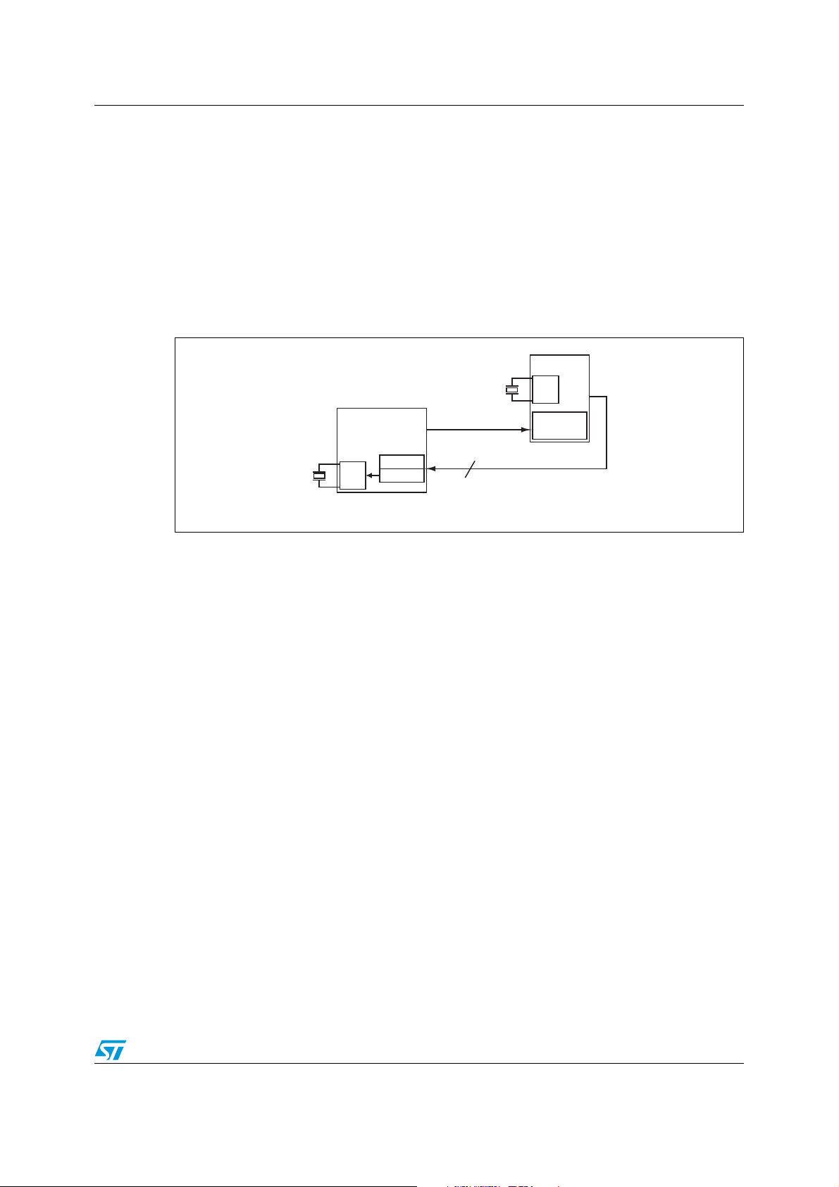
and input options, so this document can only address them in a general sense. Figure 1
shows the basic setup between the RTC and the microprocessor. The processor's timer is
used to measure the frequency of the RTC's frequency test signal (FT) and then adjust the
RTC's calibration registers as necessary via the I
Figure 1. Basic setup of microprocessor and RTC
2
C bus.
uP
OSC
TIMER
ai13995
Watch
crystal
OSC
RTC
DCAL
ACAL
AT cut
crystal
FT = 512Hz
2
I2C
Fundamentally, the processor needs to measure the period of the timer and calculate the
error or frequency deviation of the FT signal, but the measurement process is itself prone to
error. However, it should be possible to minimize that error to an acceptable level.
The key concept is that the microprocessor's timer runs off a clock signal derived from the
microprocessor's oscillator with AT cut crystal. Since this oscillator has low drift over
temperature, the timer’s clock signal will be low drift, too. Thus, using this timer, the RTC can
be calibrated to approach the accuracy of this timing chain, thus reducing the timekeeping
errors associated with watch crystals due to temperature drift.
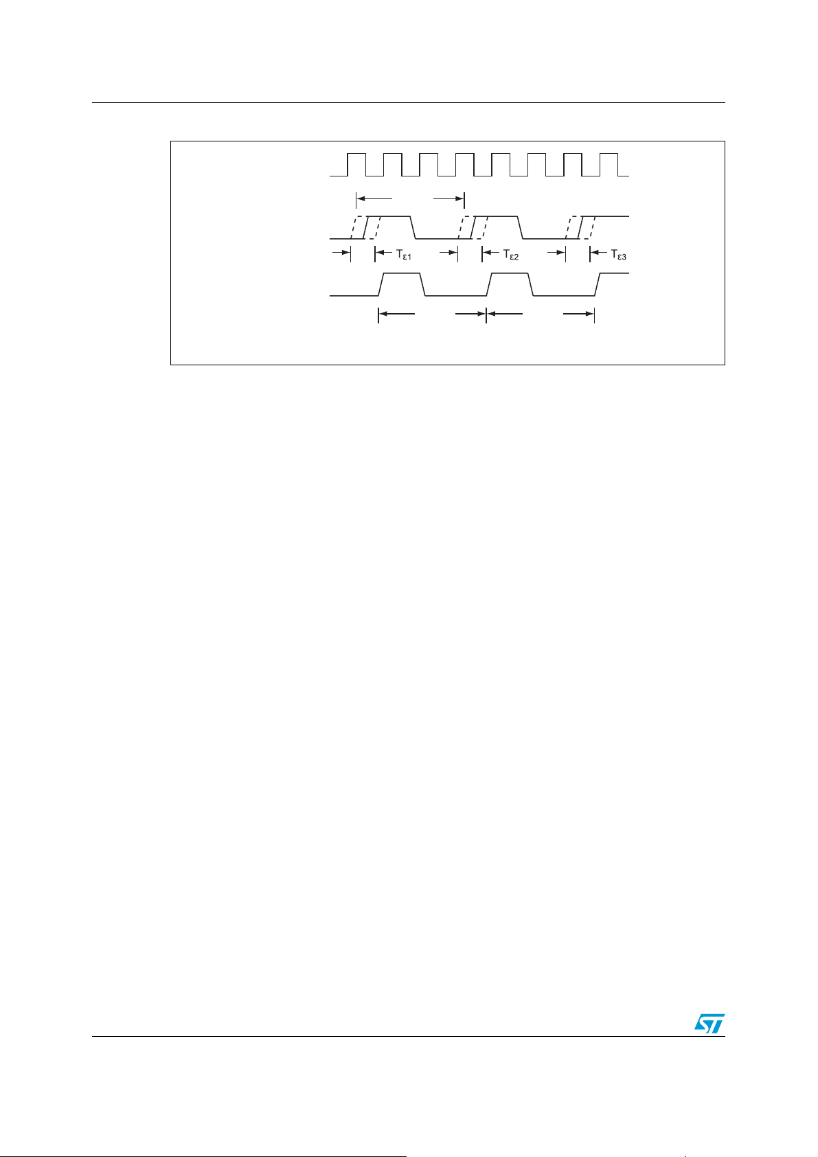
In Figure 2, the microprocessor's clock is called TCLK, and is used to sample the 512 Hz
frequency test signal, FT. Each sample includes some uncertainty. But the uncertainty
does not change as more samples are added. Thus, with many samples, the uncertainty
will be very small in comparison to the measured period.
For example, in Figure 2, the timer can detect that a transition occurred on the FT signal
between two successive samples, but it cannot determine exactly where between those
samples that it occurred. That uncertainty is labeled T
3/16
, Tε2 and Tε3 in the figure.
ε1
Page 4
M41T82-83-93 series RTCs AN2678
Figure 2. Timing uncertainty
TCLK
T
FT
FT = 512Hz
FT after
sampling
T
FTS1
T
FTS2
ai13996
The first cycle of the sampled (bottom) waveform has the period
ΤΤΤΤ −+=
12FTFTS1 εε
Similarly, the second cycle has the period
ΤΤΤΤ −+=
23FTFTS2 εε
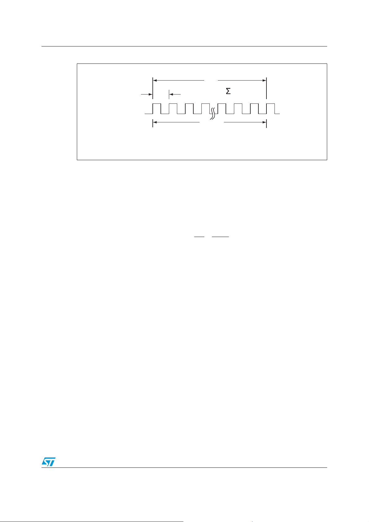
For both cycles together, the total period is
ΤΤΤ2ΤΤΤΤΤ2ΤΤ +−×=−+−+×=+
31FT2312FTFTS2FTS1 εεεεεε
This shows that the uncertainty between all the samples (except the first and last) subtracts
out of the total with the result that only the uncertainty of the first and last cycles remains.
Thus, the net uncertainty will be small compared to the overall measured period, T
N
, of
multiple samples of the 512 Hz signal, as shown in Figure 3. So, by measuring several
consecutive samples of the 512 Hz signal, the uncertainty can be minimized to an
acceptable level.
4/16
Page 5
AN2678 M41T82-83-93 series RTCs
Figure 3. Example timing
T
N
N
TN= T
i=1
i
ai13997
FT = 512Hz
T
i
N cycles
1.4 Calculating the period
As shown in Figure 3, the microprocessor will measure multiple cycles of the FT signal to
get a total period, T
. The calculated period of the 512 Hz is then
N
N
Τ
∑
Τ
Τ
512
N
N
==
i
1i
=
N
If N is sufficiently large, the uncertainty error, TεN – Tε1, can be ignored.
The microprocessor's timer will measure the T
, the period of each sample. Either software
i
or some other timer function, such as a pulse accumulator, available on many
microprocessor timers, will count the number of samples, N. Likewise T
T
, and can be accumulated in a timer function or in software. Once these are determined,
i
software will then calculate T
by dividing TN by N.
512
is the sum of the
N
5/16
Page 6

M41T82-83-93 series RTCs AN2678
1.5 Determining the error
The error formula, in ppm, where fm is the measured frequency, is below. When using a
frequency counter, this can be used to determine the error.
512f
−
ppm ×
m
=
512
The formula below can be used to determine the error when using the microprocessor timer
to determine the period, T
, of the frequency test signal.
512
Equation 1
1
Τ
−
512
ppm ×
=
Τ
512
A negative ppm means the frequency is too low and the clock is slow. Conversely, a positive
ppm means the clock is fast and thus needs to be slowed down.
512
10
10
6
6
6/16
Page 7

AN2678 Calibrating the M41T83 using analog calibration
2 Calibrating the M41T83 using analog calibration
The analog calibration procedure is performed only once, at room temperature (25°C). It
begins with determining the frequency test signal's period, T
the RTC oscillator via the analog calibration feature, and another measurement of T
made. This cycle is repeated until the error is minimized, that is, until the oscillator can be
fine tuned no further. At that point, the RTC's accuracy will be approximately equal to the
microprocessor's oscillator accuracy, which, depending on the quality of its crystal, may not
vary more than +/–5 ppm over a wide temperature range.
2.1 Analog calibration circuit
The analog calibration circuit utilizes an array of load capacitors internal to the RTC as
shown in the inset of Figure 4.
Values written to the analog calibration register add or remove load capacitance to slow
down or speed up the oscillator, respectively. The 32 KHz crystals are designed to see a
specific load capacitance. ST builds this into their real-time clocks; users do not need to add
any external capacitance to the crystals. Values programmed into the analog calibration
register adjust the amount of this built-in load capacitance seen by the crystal.
. Then, the software adjusts
512
512
is
As shown in Figure 4, two load capacitors are identified as C
are 25 pF each. The adjustment range of the RTC is such that up to 18 pF can be
subtracted from each, or up to 9.75 pF can be added making the full range of each load
capacitor 7 to 34.75 pF.
The equivalent load capacitance is the series combination of the two, and is hence
nominally 12.5 pF with a range of 3.5 pF to 17.4 pF. (In other words, for identical capacitors,
the series equivalent value is ½ the individual values.)
The asymmetry in the adjustment range is due to the fact that the crystals tend to need
speeding up much more often than they need slowing down. This is evident upon
examining the watch crystal curve in Figure 1. Thus, much more capacitance can be
subtracted from nominal than can be added.
and CXO. Nominally, these
XI
7/16
Page 8

Calibrating the M41T83 using analog calibration AN2678
Figure 4. Typical analog calibration characteristics - oscillator frequency versus load
capacitance
1 0 0 . 0
XO XI
8 0 . 0
Crystal
Oscillator
6 0 . 0
C
XI
C
XO
4 0 . 0
C
C
XI
XO
*
=
C
+ C
XI
XO
P P M A D J U S T M E N T
2 0 . 0
FASTER
DECREASING LOAD CAP.
On-Chip
C
LOAD
INCREASING LOAD CAP.
0 . 0
SLOWER
- 2 0 . 0
OFFSET TO
, C
XO
(pF)
C
XI
NET EQUIV. LOAD
CAP., C
LOAD
, (pF)
- 5 . 0 - 18.0 - 1 5 . 0 - 1 0 . 0 0 . 0 5 . 0 9.75
10 3.5 5.0 7.5 12.5 15 17.4
A n a l o g C a l i b r a t i o n
0xC8 0xBC 0xA8 0x94 0x00 0x14 0x27
V a l u e, AC,
register 0x12
Associated with this range of capacitance values, the range of frequency shift of the
oscillator is approximately –14.8 ppm up to +96.7 ppm. Several examples are shown in
Ta bl e 1 . This shift range corresponds to an approximate frequency range of 32767.514 Hz
to 32771.168 Hz.
Table 1. Analog calibration examples
Analog calibration value
Additional load capacitance 0 +3 pF +5 pF +9.75 pF –7 pF –18 pF
Total load capacitance
, C
C
XI
XO
Total equivalent load
capacitance
in series with C
C
XI
Approximate frequency shift 0 ppm –4.3 ppm –7.8 ppm –14.8 ppm +21.9 ppm +96.7 ppm
Hex 00 0C 14 27 9C C8
Bin 0000000 0 0000110 0 0001010 0 0010011 1 1001110 0 1100100 0
25 pF 28 pF 30 pF 34.75 pF 18 pF 7 pF
12.5 14 pF 15 pF 17.4 pF 9 pF 3.5 pF
XO
Nominal <––––––Slowing down––––––> <–––Speeding up–––>
ai13998
Thus, in summary, the nominal equivalent load capacitance is 12.5 pF, and can be adjusted
up to 17.4 pF or down to 3.5 pF. This corresponds to slowing the oscillator by approximately
–14.8 ppm or speeding it up by +96.7 ppm, respectively.
8/16
Page 9

AN2678 Calibrating the M41T83 using analog calibration
These are typical values. The curve in Figure 4 may be shifted up or down, left or right for a
given crystal. Because the curve is non-linear, an increment of capacitance at one operating
point will not have the same effect as an equal increment at another operating point. Thus,
table-lookup methods cannot be used with analog calibration. Instead, an iterative
procedure is required to ensure accuracy.
2.2 Analog calibration algorithm
The analog calibration algorithm described herein uses a binary tree approach for
adjustment. It utilizes repeated measurements as described in the scheme above. With
each adjustment /measurement sequence, the RTC's oscillator is fine tuned with
progressively smaller changes of the internal load capacitance array via the analog
calibration register.
As shown in Figure 5, the procedure starts with zeroing out the analog calibration register,
then waiting a few milliseconds for the oscillator to stabilize. Next, the frequency
measurement is made of the FT signal. If it is faster than 512 Hz, load capacitance is added
to the RTC's oscillator. If it is slower than 512 Hz, capacitance is removed. And if the FT
signal is exactly 512 Hz, no further adjustment is required.
Figure 5. Analog calibration algorithm
Set ACAL (012h) to 0
Wait for OSC to stabilize
FASTSLOW
Sub 4pF Add 4pF
FT?
=512
DONE
Sub 2pF Add 2pF
Sub 1pF Add 1pF
Sub 0.5pF Add 0.5pF
FT?
DONE
FT?
DONE
FT?
DONE
FT?
DONE
FASTSLOW
=512
Set ACAL (012h) to +4pFSet ACAL (012h) to –8pF
FASTSLOW
=512
FASTSLOW
=512
FASTSLOW
=512
FASTSLOW
Sub 0.25pF Add 0.25pF
DONE
FT?
DONE
=512
DONE
9/16
ai13999
Page 10

Calibrating the M41T83 using analog calibration AN2678
As the watch crystal curve of Figure 1 predicts, the RTC oscillator will tend to be slow more
often than fast, so the adjustment range of the part is asymmetric; there is more range for
increasing the RTC oscillator speed than for slowing it down.
For the M41T82, M41T83 and M41T93 RTCs, the smallest incremental adjustments are
step sizes of approximately 0.25 pF. One step of 0.25 pF is roughly 0.5 ppm.
Since this algorithm uses a binary tree approach, each increment of capacitance must be a
power of 2 times 0.25 pF. That is, capacitance will be added and/or subtracted in
increments of 8 pF, 4 pF, 2 pF, 1 pF, 0.5 pf or 0.25 pF.
Thus, although up to 18.0 pF can be subtracted or up to 9.75 pF can be added, the power of
2 restriction constrains these limits to –16 pF and +8 pF, respectively. As a result, this
algorithm does not use the total available adjustment range, but that will not be a problem in
most applications.
For example, with this approach, when capacitance is to be added, instead of starting at half
the maximum available, ½ x 9.75 pF (= 4.875 pF), the power of 2 nearest that is used, which
is 4 pF. Similarly, for removing capacitance, the most that can be subtracted is 18 pF, so the
algorithm starts at the power of 2 nearest ½ x 18, or 8 pF.
Returning to Figure 5, after making the first measurement of FT, if capacitance is added, as
shown on the right, the ACAL value is adjusted to 4 pF. Then, progressively smaller
increments of capacitance are added or removed, until the frequency error measured on the
FT pin is minimized.
If, in Figure 5, the first test of the FT signal indicates that capacitance must be removed (that
the RTC is slow), the analog calibration register is set to –8 pF and then progressively
smaller increments of capacitance are added or removed.
Each time the analog calibration register is adjusted, the oscillator must be allowed time to
settle before taking another measurement. This is shown at the top of Figure 5, but not
shown in successive steps for the sake of brevity. However, it is still required each time the
register is written.
Using this binary approach, each of the 25 pF capacitors can be increased by up to 7.75 pF
or decreased by up to 15.75 pF. While these adjustment limits are slightly less than the
absolute limits available - up to a 9.75 pF increase or 18 pF decrease - they should cover all
except the most extreme cases of RTC oscillator error.
It may be possible to use the wider, available adjustment limits in an adaptive calibration
scheme like this one, but when increments other than powers of 2 are used, the algorithm
becomes much, much more complex and thus may not be as easy for users to implement.
Once the final calibration bit has been determined, the user should record the value in nonvolatile memory so that it can be retrieved by the microprocessor when necessary.
If a frequency counter was used to perform the measurements during the analog calibration
procedure, the user should immediately follow that with the additional step of using the
microprocessor and its timer to measure the period of the FT signal out of the real-time
clock as described in Section 1.3 and 1.4. This is done to establish the initial error, if any, in
the microprocessor’s timing chain at room temperature. This value should also be stored in
non-volatile memory.
10/16
Page 11

AN2678 Digital calibration
3 Digital calibration
The digital calibration feature of the M41T82, M41T83 and M41T93 uses periodic counter
correction. The clock counters are adjusted by adding or subtracting pulses at the 512 Hz
divider stage. This approach provides compensation over an approximate range of –63 ppm
to +126 ppm.
This method employs the use of periodic counter correction by adjusting the ratio of the 100
Hz divider stage to the 512 Hz divider stage. Under normal operation, the 100 Hz divider
stage outputs precisely 100 pulses for every 512 pulses of the 512 Hz stage. This 100 Hz
signal is the input to the counter for the 10ths/100ths of seconds register in the RTC. By
adjusting the number of 512 Hz input pulses used to generate 100 output pulses, the clock
can be sped up or slowed down. To provide digital correction, the device will, depending on
the digital calibration value, periodically produce one or more long or short seconds.
When a non-zero value is loaded into the five Calibration Bits (DC4 - DC0) of the Digital
Calibration Register (0x08) and the sign bit is 1, (indicating positive calibration), the 100 Hz
stage will output 100 pulses for every 511 input pulses instead of the normal 512. Since the
100 pulses are now being output in a shorter window, this has the effect of speeding up the
clock by 1/512 seconds for each second the circuit is active.
Table 2. Digital calibration values
Calibration value, DC4-DC0
Decimal Binary
0 00000 – 0 ppm + 0 ppm
1 00001 – 2 ppm + 4 ppm
2 00010 – 4 ppm + 8 ppm
3 00011 – 6 ppm + 12 ppm
4 00100 – 8 ppm + 16 ppm
5 00101 – 10 ppm + 20 ppm
6 00110 – 12 ppm + 24 ppm
7 00111 – 14 ppm + 28 ppm
8 01000 – 16 ppm + 33 ppm
9 01001 – 18 ppm + 37 ppm
10 01010 – 20 ppm + 41 ppm
11 01011 – 22 ppm + 45 ppm
12 01100 – 24 ppm + 49 ppm
13 01101 – 26 ppm + 53 ppm
Calibration effect, in ppm,
rounded to the nearest integer
Slowing
Sign DCS = 0
negative calibration
Speeding
Sign DCS = 1
positive calibration
14 01110 – 28 ppm + 57 ppm
15 01111 – 31 ppm + 61 ppm
11/16
Page 12

Digital calibration AN2678
Table 2. Digital calibration values (continued)
Calibration value, DC4-DC0
Decimal Binary
negative calibration
16 10000 – 33 ppm + 65 ppm
17 10001 – 35 ppm + 69 ppm
18 10010 – 37 ppm + 73 ppm
19 10011 – 39 ppm + 77 ppm
20 10100 – 41 ppm + 81 ppm
21 10101 – 43 ppm + 85 ppm
22 10110 – 45 ppm + 90 ppm
23 10111 – 47 ppm + 94 ppm
24 11000 – 49 ppm + 98 ppm
25 11001 – 51 ppm + 102 ppm
26 11010 – 53 ppm + 106 ppm
27 11011 – 55 ppm + 110 ppm
28 11100 – 57 ppm + 114 ppm
29 11101 – 59 ppm + 118 ppm
30 11110 – 61 ppm + 122 ppm
Calibration effect, in ppm,
rounded to the nearest integer
Slowing
Sign DCS = 0
positive calibration
Speeding
Sign DCS = 1
31 11111 – 63 ppm + 126 ppm
N –N/491520 (per minute) +N/245760 (per minute)
Similarly, when the sign bit is 0, indicating negative calibration, the block will output 100
pulses for every 513 input pulses. Since the 100 pulses are then being output in a longer
window, this has the effect of slowing down the clock by 1/512 seconds for each second the
circuit is active.
The overall amount of calibration is controlled using the value (N) in the digital calibration
register to generate the adjustments in one second increments. N is the number of affected
seconds in the correction period. For positive calibration (speeding up), corrections are
made to each of the first N seconds of every eight minute interval. For negative calibration
(slowing down), corrections are made to each of the first N seconds of every 16-minute
interval.
Thus, when speeding up, the first N seconds of every 480 second span (ie, every 8-minute
span) are each slightly shorter. And when slowing down, the first N seconds of each 960
second span (ie, 16 minutes) are slightly longer.
To use the digital calibration feature, the measurement technique described in Section 1 is
used - the 512 Hz frequency test signal is measured by the microprocessor's timer.
12/16
Page 13

AN2678 Digital calibration
Depending on whether this timer was also used to perform the initial analog calibration, an
adjustment may need to made to this number . Once the adjusted number is determined,
the error in ppm is calculated and the appropriate offset from Ta bl e 2 is selected and
programmed into the digital calibration register.
Example 1: A frequency counter was used during analog calibration, and the subsequent
period measured and calculated using the microprocessor’s timer was 0.0019531441
seconds. Ideally, this number would be 0.0019531250 (= 1/512). Thus, the microprocessor’s
timer is about 10 ppm fast, and the earlier number, 0.0019531441, will be used in place of
1/512 in Equation 1. Given a current calculated period of 0.0019531536, this is inserted into
Equation 1 for T
, and the resultant error is –4.88 ppm. So the RTC should be adjusted by
512
the opposite amount. In Ta b le 2 , the positive value nearest this is +4 ppm, so the digital
calibration register would get would get DCS = 1 and DC4:DC0 = 00001.
Example 2: The microprocessor’s timer was used during analog calibration. As in example
1, let the calculated period be 0.0019531536 seconds. Inserting this into Equation 1 (and
retaining the 1/512), we get –14.65 ppm. The nearest opposite value is +16 ppm. For this,
DCS = 1 and DC4:DC0 = 00100.
With digital calibration, the adjustments are made open-loop. In the case of the analog
calibration adjustments, the frequency shift of the oscillator can be seen in the 512 Hz test
signal, but with the digital calibration, the effects are spread out over time and are not
immediately observable upon making changes. Furthermore, with digital calibration, no
iteration is required. Once the frequency error is known, an appropriate value is
programmed into the part and no further adjustments are made for while. The key idea is
that adjusting the digital calibration requires one measurement followed by one adjustment;
no looping is required.
This digital calibration procedure is repeated often enough to prevent the RTC from drifting
too far, but no more often than every 16 minutes, the interval at which the RTC digital
calibration algorithm updates. This can be reduced to 8 minutes when positive calibration
values are being used. As the ambient temperature changes, the oscillator will drift, and the
RTC oscillator will need adjustment. This can be done periodically by scheduling
calibrations, or, if a temperature sensor is available to the microprocessor, by monitoring for
changes in the temperature and adjusting the RTC when they occur. Or, a combination of
both might be utilized. For example, scheduled RTC calibrations might occur every hour,
and unscheduled ones might be run whenever a 2 degree temperature shift is detected.
As long as the microprocessor periodically adjusts the RTC, its timekeeping accuracy will be
optimized, and timekeeping errors minimized.
13/16
Page 14

Conclusion AN2678
4 Conclusion
By taking advantage of the analog calibration feature built into the new M41T82/83/93 family
of serial RTCs, a low cost clock with high accuracy across temperature can be achieved.
This approach requires only the use of the microprocessor timer to periodically measure the
RTC's true frequency. Initially, the analog calibration is adjusted at room temperature.
Then, periodic updates to the digital calibration register are made to compensate for any
RTC oscillator drift due to temperature changes which may occur. During the analog
calibration, a simple binary decision tree is employed which allows the user to fine tune the
clock's oscillator and zero out any frequency shift. Subsequent digital calibration
adjustments use a look-up-table.
Using this combination of analog and digital calibration enables the user to have a simple
periodic update scheme which requires low overhead while providing accurate timekeeping
and minimal cost.
14/16
Page 15

AN2678 Revision history
5 Revision history
Table 3. Document revision history
Date Revision Changes
20-Dec-2007 1 Initial release.
26-Nov-2008 2 Updated Figure 1.
15/16
Page 16

AN2678
Please Read Carefully:
Information in this document is provided solely in connection with ST products. STMicroelectronics NV and its subsidiaries (“ST”) reserve the
right to make changes, corrections, modifications or improvements, to this document, and the products and services described herein at any
time, without notice.
All ST products are sold pursuant to ST’s terms and conditions of sale.
Purchasers are solely responsible for the choice, selection and use of the ST products and services described herein, and ST assumes no
liability whatsoever relating to the choice, selection or use of the ST products and services described herein.
No license, express or implied, by estoppel or otherwise, to any intellectual property rights is granted under this document. If any part of this
document refers to any third party products or services it shall not be deemed a license grant by ST for the use of such third party products
or services, or any intellectual property contained therein or considered as a warranty covering the use in any manner whatsoever of such
third party products or services or any intellectual property contained therein.
UNLESS OTHERWISE SET FORTH IN ST’S TERMS AND CONDITIONS OF SALE ST DISCLAIMS ANY EXPRESS OR IMPLIED
WARRANTY WITH RESPECT TO THE USE AND/OR SALE OF ST PRODUCTS INCLUDING WITHOUT LIMITATION IMPLIED
WARRANTIES OF MERCHANTABILITY, FITNESS FOR A PARTICULAR PURPOSE (AND THEIR EQUIVALENTS UNDER THE LAWS
OF ANY JURISDICTION), OR INFRINGEMENT OF ANY PATENT, COPYRIGHT OR OTHER INTELLECTUAL PROPERTY RIGHT.
UNLESS EXPRESSLY APPROVED IN WRITING BY AN AUTHORIZED ST REPRESENTATIVE, ST PRODUCTS ARE NOT
RECOMMENDED, AUTHORIZED OR WARRANTED FOR USE IN MILITARY, AIR CRAFT, SPACE, LIFE SAVING, OR LIFE SUSTAINING
APPLICATIONS, NOR IN PRODUCTS OR SYSTEMS WHERE FAILURE OR MALFUNCTION MAY RESULT IN PERSONAL INJURY,
DEATH, OR SEVERE PROPERTY OR ENVIRONMENTAL DAMAGE. ST PRODUCTS WHICH ARE NOT SPECIFIED AS "AUTOMOTIVE
GRADE" MAY ONLY BE USED IN AUTOMOTIVE APPLICATIONS AT USER’S OWN RISK.
Resale of ST products with provisions different from the statements and/or technical features set forth in this document shall immediately void
any warranty granted by ST for the ST product or service described herein and shall not create or extend in any manner whatsoever, any
liability of ST.
ST and the ST logo are trademarks or registered trademarks of ST in various countries.
Information in this document supersedes and replaces all information previously supplied.
The ST logo is a registered trademark of STMicroelectronics. All other names are the property of their respective owners.
© 2008 STMicroelectronics - All rights reserved
STMicroelectronics group of companies
Australia - Belgium - Brazil - Canada - China - Czech Republic - Finland - France - Germany - Hong Kong - India - Israel - Italy - Japan -
Malaysia - Malta - Morocco - Singapore - Spain - Sweden - Switzerland - United Kingdom - United States of America
www.st.com
16/16
 Loading...