

Page 1

AN2629
Application note
STM32F101xx, STM32F102xx and STM32F103xx
low-power modes
Introduction
This application note is intended for system designers who require a software and hardware
implementation overview of the low-power modes of the STM32F101xx, STM32F102xx and
STM32F103xx products. It describes how to use the STM32F10xxx product family and
details the clock systems, register settings and low-power management in order to optimize
the use of STM32F10xxx in applications where low power is key.
This application note should be read in conjunction with the datasheet of the relevant
STM32F10xxx product and the STM32F10xxx reference manual. For information on
programming, erasing and protection of the internal Flash memory please refer to the
STM32F10xxx Flash programming manual.
The STM32F10xxx datasheets, the reference and Flash programming manuals are all
available from the STMicroelectronics website www.st.com.
For information on the Cortex™-M3 core please refer to the Cortex™-M3 Technical
Reference Manual, available from the www.arm.com website at the following address:
http://infocenter.arm.com/help/index.jsp?topic=/com.arm.doc.ddi0337e/.
The first four sections of this application note introduce the part of the STM32F10xxx
devices that is used for low-power configuration. The next sections demonstrate the lowpower feature in an applicative way. Each section refers to software delivered with this
document, which give a practical view of power optimization.
April 2009 Doc ID 13922 Rev 2 1/43
www.st.com
Page 2

Contents AN2629
Contents
1 Power supply . . . . . . . . . . . . . . . . . . . . . . . . . . . . . . . . . . . . . . . . . . . . . . . 7
1.1 Introduction . . . . . . . . . . . . . . . . . . . . . . . . . . . . . . . . . . . . . . . . . . . . . . . . 7
1.1.1 Independent A/D converter supply and reference voltage . . . . . . . . . . . . 7
1.1.2 Battery backup . . . . . . . . . . . . . . . . . . . . . . . . . . . . . . . . . . . . . . . . . . . . . 8
1.1.3 Voltage regulator . . . . . . . . . . . . . . . . . . . . . . . . . . . . . . . . . . . . . . . . . . . 8
1.2 Low-power modes . . . . . . . . . . . . . . . . . . . . . . . . . . . . . . . . . . . . . . . . . . . 8
1.2.1 Slowing down system clocks . . . . . . . . . . . . . . . . . . . . . . . . . . . . . . . . . . 9
1.2.2 Peripheral clock gating . . . . . . . . . . . . . . . . . . . . . . . . . . . . . . . . . . . . . . . 9
1.2.3 Sleep mode . . . . . . . . . . . . . . . . . . . . . . . . . . . . . . . . . . . . . . . . . . . . . . 10
1.2.4 Stop mode . . . . . . . . . . . . . . . . . . . . . . . . . . . . . . . . . . . . . . . . . . . . . . . 11
1.2.5 Standby mode . . . . . . . . . . . . . . . . . . . . . . . . . . . . . . . . . . . . . . . . . . . . 12
1.2.6 Debug mode . . . . . . . . . . . . . . . . . . . . . . . . . . . . . . . . . . . . . . . . . . . . . 13
1.2.7 Auto-wakeup (AWU) from low-power mode . . . . . . . . . . . . . . . . . . . . . . 13
2 Clock . . . . . . . . . . . . . . . . . . . . . . . . . . . . . . . . . . . . . . . . . . . . . . . . . . . . . 14
3 Real-time clock (RTC) . . . . . . . . . . . . . . . . . . . . . . . . . . . . . . . . . . . . . . . 16
3.1 Introduction . . . . . . . . . . . . . . . . . . . . . . . . . . . . . . . . . . . . . . . . . . . . . . . 16
3.2 Main features . . . . . . . . . . . . . . . . . . . . . . . . . . . . . . . . . . . . . . . . . . . . . . 16
3.3 Functional description . . . . . . . . . . . . . . . . . . . . . . . . . . . . . . . . . . . . . . . 16
3.3.1 Overview . . . . . . . . . . . . . . . . . . . . . . . . . . . . . . . . . . . . . . . . . . . . . . . . 16
3.3.2 Resetting RTC registers . . . . . . . . . . . . . . . . . . . . . . . . . . . . . . . . . . . . . 18
3.3.3 Reading RTC registers . . . . . . . . . . . . . . . . . . . . . . . . . . . . . . . . . . . . . 18
3.3.4 Configuring RTC registers . . . . . . . . . . . . . . . . . . . . . . . . . . . . . . . . . . . 18
3.3.5 RTC flag assertion . . . . . . . . . . . . . . . . . . . . . . . . . . . . . . . . . . . . . . . . . 19
4 Backup registers (BKP) . . . . . . . . . . . . . . . . . . . . . . . . . . . . . . . . . . . . . 20
4.1 Introduction . . . . . . . . . . . . . . . . . . . . . . . . . . . . . . . . . . . . . . . . . . . . . . . 20
4.2 Features . . . . . . . . . . . . . . . . . . . . . . . . . . . . . . . . . . . . . . . . . . . . . . . . . . 20
4.3 Tamper detection . . . . . . . . . . . . . . . . . . . . . . . . . . . . . . . . . . . . . . . . . . . 20
4.4 RTC calibration . . . . . . . . . . . . . . . . . . . . . . . . . . . . . . . . . . . . . . . . . . . . . 21
5 Power and wakeup time measurement . . . . . . . . . . . . . . . . . . . . . . . . . 22
5.1 Introduction . . . . . . . . . . . . . . . . . . . . . . . . . . . . . . . . . . . . . . . . . . . . . . . 22
2/43 Doc ID 13922 Rev 2
Page 3

AN2629 Contents
5.2 Power measurement . . . . . . . . . . . . . . . . . . . . . . . . . . . . . . . . . . . . . . . . 22
5.2.1 Context . . . . . . . . . . . . . . . . . . . . . . . . . . . . . . . . . . . . . . . . . . . . . . . . . . 22
5.2.2 Detailed description . . . . . . . . . . . . . . . . . . . . . . . . . . . . . . . . . . . . . . . . 22
5.2.3 Measurement results . . . . . . . . . . . . . . . . . . . . . . . . . . . . . . . . . . . . . . . 25
5.3 Wakeup time measurement . . . . . . . . . . . . . . . . . . . . . . . . . . . . . . . . . . . 26
5.3.1 Context . . . . . . . . . . . . . . . . . . . . . . . . . . . . . . . . . . . . . . . . . . . . . . . . . . 26
5.3.2 Detailed description . . . . . . . . . . . . . . . . . . . . . . . . . . . . . . . . . . . . . . . . 27
5.3.3 Measurement results . . . . . . . . . . . . . . . . . . . . . . . . . . . . . . . . . . . . . . . 28
5.3.4 Conclusion . . . . . . . . . . . . . . . . . . . . . . . . . . . . . . . . . . . . . . . . . . . . . . . 29
6 Optimizing power consumption in your application . . . . . . . . . . . . . . 30
6.1 Introduction . . . . . . . . . . . . . . . . . . . . . . . . . . . . . . . . . . . . . . . . . . . . . . . 30
6.2 Using the advance clock configuration of the STM32F10xxx . . . . . . . . . . 30
6.2.1 Context . . . . . . . . . . . . . . . . . . . . . . . . . . . . . . . . . . . . . . . . . . . . . . . . . . 30
6.2.2 Detailed description . . . . . . . . . . . . . . . . . . . . . . . . . . . . . . . . . . . . . . . . 30
6.3 Typical measurement results . . . . . . . . . . . . . . . . . . . . . . . . . . . . . . . . . . 33
6.4 Conclusion . . . . . . . . . . . . . . . . . . . . . . . . . . . . . . . . . . . . . . . . . . . . . . . . 33
7 Using the Stop and Standby mode in battery-operated applications 35
7.1 Introduction . . . . . . . . . . . . . . . . . . . . . . . . . . . . . . . . . . . . . . . . . . . . . . . 35
7.2 Using Wait For Event & Stop Wait For Event . . . . . . . . . . . . . . . . . . . . . . 35
7.2.1 Context . . . . . . . . . . . . . . . . . . . . . . . . . . . . . . . . . . . . . . . . . . . . . . . . . . 35
7.2.2 Detailed description . . . . . . . . . . . . . . . . . . . . . . . . . . . . . . . . . . . . . . . . 36
7.3 Using the Standby mode in an applicative way . . . . . . . . . . . . . . . . . . . . 37
7.3.1 Context . . . . . . . . . . . . . . . . . . . . . . . . . . . . . . . . . . . . . . . . . . . . . . . . . . 37
7.3.2 Detailed description . . . . . . . . . . . . . . . . . . . . . . . . . . . . . . . . . . . . . . . . 37
7.4 Typical measurement results . . . . . . . . . . . . . . . . . . . . . . . . . . . . . . . . . . 38
7.5 Conclusion . . . . . . . . . . . . . . . . . . . . . . . . . . . . . . . . . . . . . . . . . . . . . . . . 39
8 Using the Backup domain in very low-power applications . . . . . . . . . 40
8.1 Introduction . . . . . . . . . . . . . . . . . . . . . . . . . . . . . . . . . . . . . . . . . . . . . . . 40
8.2 Using the Backup domain in an applicative way . . . . . . . . . . . . . . . . . . . 40
8.2.1 Context . . . . . . . . . . . . . . . . . . . . . . . . . . . . . . . . . . . . . . . . . . . . . . . . . . 40
8.2.2 Detailed description . . . . . . . . . . . . . . . . . . . . . . . . . . . . . . . . . . . . . . . . 40
8.3 Conclusion . . . . . . . . . . . . . . . . . . . . . . . . . . . . . . . . . . . . . . . . . . . . . . . . 41
Doc ID 13922 Rev 2 3/43
Page 4

Contents AN2629
9 Revision history . . . . . . . . . . . . . . . . . . . . . . . . . . . . . . . . . . . . . . . . . . . 42
4/43 Doc ID 13922 Rev 2
Page 5

AN2629 List of tables
List of tables
Table 1. Low-power modes . . . . . . . . . . . . . . . . . . . . . . . . . . . . . . . . . . . . . . . . . . . . . . . . . . . . . . . . 9
Table 2. Sleep-now. . . . . . . . . . . . . . . . . . . . . . . . . . . . . . . . . . . . . . . . . . . . . . . . . . . . . . . . . . . . . . 10
Table 3. Sleep-on-exit. . . . . . . . . . . . . . . . . . . . . . . . . . . . . . . . . . . . . . . . . . . . . . . . . . . . . . . . . . . . 11
Table 4. Stop mode . . . . . . . . . . . . . . . . . . . . . . . . . . . . . . . . . . . . . . . . . . . . . . . . . . . . . . . . . . . . . 12
Table 5. Standby mode. . . . . . . . . . . . . . . . . . . . . . . . . . . . . . . . . . . . . . . . . . . . . . . . . . . . . . . . . . . 13
Table 6. Power measurement results in Sleep mode . . . . . . . . . . . . . . . . . . . . . . . . . . . . . . . . . . . . 25
Table 7. Power measurement for Stop and Standby modes . . . . . . . . . . . . . . . . . . . . . . . . . . . . . . 26
Table 8. Wakeup time measurement results . . . . . . . . . . . . . . . . . . . . . . . . . . . . . . . . . . . . . . . . . . 29
Table 9. Example measurements . . . . . . . . . . . . . . . . . . . . . . . . . . . . . . . . . . . . . . . . . . . . . . . . . . . 33
Table 10. Example measurements . . . . . . . . . . . . . . . . . . . . . . . . . . . . . . . . . . . . . . . . . . . . . . . . . . . 38
Table 11. Document revision history . . . . . . . . . . . . . . . . . . . . . . . . . . . . . . . . . . . . . . . . . . . . . . . . . 42
Doc ID 13922 Rev 2 5/43
Page 6

List of figures AN2629
List of figures
Figure 1. Power supply overview . . . . . . . . . . . . . . . . . . . . . . . . . . . . . . . . . . . . . . . . . . . . . . . . . . . . . 7
Figure 2. Clock tree . . . . . . . . . . . . . . . . . . . . . . . . . . . . . . . . . . . . . . . . . . . . . . . . . . . . . . . . . . . . . . 15
Figure 3. RTC simplified block diagram . . . . . . . . . . . . . . . . . . . . . . . . . . . . . . . . . . . . . . . . . . . . . . . 17
Figure 4. RTC second and alarm waveform example with PR=0003, ALARM=00004 . . . . . . . . . . . 19
Figure 5. RTC Overflow waveform example with PR=0003. . . . . . . . . . . . . . . . . . . . . . . . . . . . . . . . 19
Figure 6. HyperTerminal time adjustment interface . . . . . . . . . . . . . . . . . . . . . . . . . . . . . . . . . . . . . . 31
Figure 7. WFE & STOP WFE. . . . . . . . . . . . . . . . . . . . . . . . . . . . . . . . . . . . . . . . . . . . . . . . . . . . . . . 36
Figure 8. Standby. . . . . . . . . . . . . . . . . . . . . . . . . . . . . . . . . . . . . . . . . . . . . . . . . . . . . . . . . . . . . . . . 37
Figure 9. HyperTerminal display of time . . . . . . . . . . . . . . . . . . . . . . . . . . . . . . . . . . . . . . . . . . . . . . 40
6/43 Doc ID 13922 Rev 2
Page 7
AN2629 Power supply
A/D converter
V
DDA
V
DD
V
SSA
(3.3 V)
V
REF+
V
BAT
V
SS
I/O Ring
(V
DD
)
(V
DD
)
(from 2 V up to V
DDA
)
BKP registers
Temp. sensor
Reset block
Standby circuitry
PLL
(Wakeup logic,
IWDG)
RTC
Voltage Regulator
Core
Memories
digital
peripherals
Low voltage detector
V
REF-
V
DDA
domain
V
DD
domain
1.8 V domain
Backup domain
LSE crystal 32K osc
RCC BDCR register
(V
SSA
)
ai14677
1 Power supply
1.1 Introduction
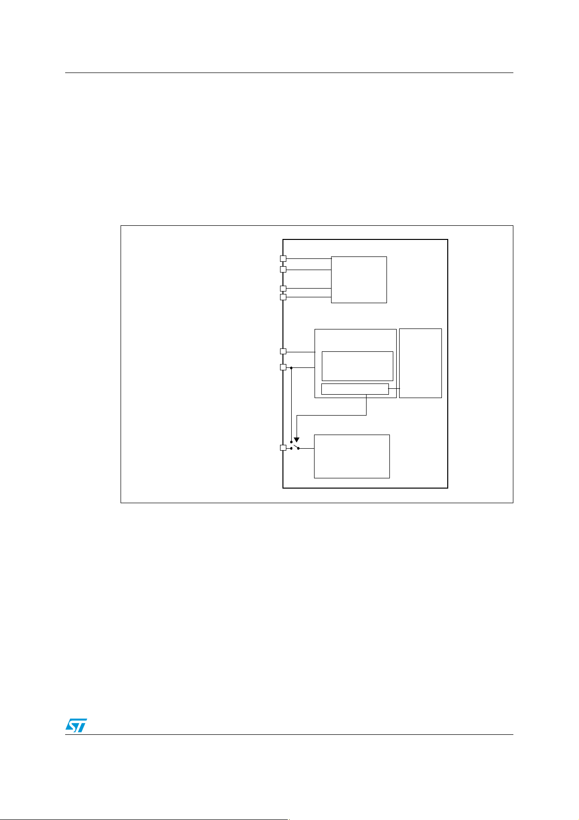
The device requires a 2.0 V to 3.6 V operating voltage supply (VDD). An embedded regulator
is used to supply the internal 1.8 V digital power.
The real-time clock (RTC) and backup registers can be powered from the V
the main V
supply is powered off.
DD
Figure 1. Power supply overview
voltage when
BAT
1.1.1 Independent A/D converter supply and reference voltage
To improve conversion accuracy, the ADC has an independent power supply that can be
filtered separately, and shielded from noise on the PCB.
● The ADC voltage supply input is available on a separate V
● An isolated supply ground connection is provided on the V
When available (depending on package), V
must be tied to V
REF–
DDA
SSA
SSA
pin
pin
.
On 100-pin packages
To ensure a better accuracy on low-voltage inputs, the user can connect a separate external
reference voltage ADC input on V
. The voltage on V
REF+
may range from 2.0 V to V
REF+
Doc ID 13922 Rev 2 7/43
DDA
.
Page 8

Power supply AN2629
On packages with 64 pins or less
REF+
and V
REF-
DDA
The V
voltage supply (V
1.1.2 Battery backup
To retain the content of the Backup registers when VDD is turned off, the V
connected to an optional standby voltage supplied by a battery or another source.
The V
digital supply (V
pin also powers the RTC unit, allowing the RTC to operate even when the main
BAT
) is turned off. Switching to the V
DD
down reset (PDR) circuitry embedded in the Reset block.
If no external battery is used in the application, V
1.1.3 Voltage regulator
The voltage regulator is always enabled after reset. It works in three different modes
depending on the application modes:
● in Run mode, the regulator supplies full power to the 1.8 V domain (core, memories and
digital peripherals)
● in Stop mode, the regulator supplies low power to the 1.8 V domain, preserving the
contents of the registers and SRAM
● in Standby mode, the regulator is powered off. The contents of the registers and SRAM
are lost except for those concerned with the Standby circuitry and the Backup domain.
pins are not available, they are internally connected to the ADC
) and ground (V
SSA
).
pin can be
BAT
supply is controlled by the power
BAT
must be connected externally to VDD.
BAT
1.2 Low-power modes
By default, the microcontroller is in Run mode after a system or a power Reset. Several lowpower modes are available to save power when the CPU does not need to be kept running,
for example when waiting for an external event. It is up to the user to select the mode that
gives the best compromise between low-power consumption, short startup time and
available wakeup sources.
The STM32F10xxx devices feature three low-power modes:
● Sleep mode (CPU clock off, all peripherals including Cortex-M3 core peripherals like
NVIC, SysTick, etc. are kept running)
● Stop mode (all clocks are stopped)
● Standby mode (1.8V domain powered-off)
In addition, the power consumption in Run mode can be reduce by one of the following
means:
● Slowing down the system clocks
● Gating the clocks to the APB and AHB peripherals when they are unused.
Ta bl e 1 below summarizes the low-power modes of the STM32F10xxx MCU.
8/43 Doc ID 13922 Rev 2
Page 9

AN2629 Power supply
Table 1. Low-power modes
Mode name Entry Wakeup
Sleep
WFI Any interrupt CPU clock OFF
(Sleep-now
or Sleep-on-
WFE Wakeup event
exit)
PDDS and
Stop
LPDS bits +
SLEEPDEEP
bit + WFI or
Any EXTI line
(configured in the EXTI
registers)
WFE
Standby
PDDS bit +
SLEEPDEEP
bit + WFI or
WFE
WKUP pin rising edge,
RTC alarm, external
reset in NRST pin,
IWDG reset
1.2.1 Slowing down system clocks
Effect on 1.8 V
domain clocks
No effect on other
clocks or analog
clock sources
All 1.8 V domain
clocks OF
Effect on
VDD domain
clocks
Vol tag e
regulator
None ON
ON or in
low-power
mode
(depends
on the
Power
HSI and HSE
oscillators
OFF
control
register,
PWR_CR
)
OFF
In Run mode the speed of the system clocks (SYSCLK, HCLK, PCLK1, PCLK2) can be
reduced by programming the prescaler registers. These prescalers can also be used to slow
down peripherals before entering Sleep mode.
1.2.2 Peripheral clock gating
In Run mode, the HCLK and PCLKx for individual peripherals and memories can be stopped
at any time to reduce power consumption.
To further reduce power consumption in Sleep mode the peripheral clocks can be disabled
prior to executing the WFI or WFE instructions.
Peripheral clock gating is controlled by the AHB peripheral clock enable register
(RCC_AHBENR), the APB1 peripheral clock enable register (RCC_APB1ENR) and the
APB2 peripheral clock enable register (RCC_APB2ENR).
Doc ID 13922 Rev 2 9/43
Page 10

Power supply AN2629
1.2.3 Sleep mode
Entering Sleep mode
The Sleep mode is entered by executing the WFI (Wait For Interrupt) or WFE (Wait for
Event) instructions. Two options are available to select the Sleep mode entry mechanism,
depending on the SLEEPONEXIT bit in the Cortex-M3 System Control register:
● Sleep-now: if the SLEEPONEXIT bit is cleared, the MCU enters Sleep mode as soon
as WFI or WFE instruction is executed.
● Sleep-on-exit: if the SLEEPONEXIT bit is set, the MCU enters Sleep mode as soon as
it exits the lowest priority ISR.
In the Sleep mode, all I/O pins keep the same state as in the Run mode.
Refer to Table 2 and Table 3 for details on how to enter Sleep mode.
Exiting Sleep mode
If the WFI instruction is used to enter Sleep mode, any peripheral interrupt acknowledged by
the nested vectored interrupt controller (NVIC) can wake up the device from Sleep mode.
If the WFE instruction is used to enter Sleep mode, the MCU exits Sleep mode as soon as
an event occurs. The wakeup event can be generated either by:
● enabling an interrupt in the peripheral control register but not in the NVIC, and enabling
the SEVONPEND bit in the Cortex-M3 System Control register. When the MCU
resumes from WFE, the peripheral interrupt pending bit and the peripheral NVIC IRQ
channel pending bit (in the NVIC interrupt clear pending register) have to be cleared.
● or configuring an external or internal EXTI line in event mode. When the CPU resumes
from WFE, it is not necessary to clear the peripheral interrupt pending bit or the NVIC
IRQ channel pending bit as the pending bit corresponding to the event line is not set.
This mode offers the lowest wakeup time as no time is wasted in interrupt entry/exit.
Refer to Table 2 and Table 3 for more details on how to exit Sleep mode.
Table 2. Sleep-now
Sleep-now Description
WFI (Wait for Interrupt) or WFE (Wait for Event) while:
Mode entry
Mode exit
Wakeup latency None.
– SLEEPDEEP = 0 and
– SLEEPONEXIT = 0
Refer to the Cortex-M3 System Control register.
If WFI was used for entry ->Interrupt
If WFE was used for entry ->Wakeup event
10/43 Doc ID 13922 Rev 2
Page 11

AN2629 Power supply
Table 3. Sleep-on-exit
Sleep-on-exit Description
WFI (wait for interrupt) while:
Mode entry
SLEEPDEEP = 0 and
SLEEPONEXIT = 1
Refer to the Cortex™-M3 System Control register.
Mode exit Interrupt.
Wakeup latency None.
1.2.4 Stop mode
The Stop mode is based on the Cortex-M3 deepsleep mode combined with peripheral clock
gating. The voltage regulator can be configured either in normal or low-power mode. In Stop
mode, all clocks in the 1.8 V domain are stopped, the PLL, the HSI and the HSE RC
oscillators are disabled. SRAM and register contents are preserved.
In the Stop mode, all I/O pins keep the same state as in the Run mode.
Entering the Stop mode
Refer to Table 4 for details on how to enter the Stop mode.
To further reduce power consumption in Stop mode, the internal voltage regulator can be
put in low-power mode. This is configured by the LPDS bit of the Power control register
(PWR_CR).
If Flash memory programming is ongoing, the Stop mode entry is delayed until the memory
access is finished.
If an access to the APB domain is ongoing, The Stop mode entry is delayed until the APB
access is finished.
In Stop mode, the following features can be selected by programming individual control bits:
● Independent watchdog (IWDG): the IWDG is started by writing to its Key register or by
hardware option. Once started it cannot be stopped except by a Reset.
● Real-time clock (RTC): this is configured by the RTCEN bit in the Backup domain
control register (RCC_BDCR)
● Internal RC oscillator (LSI RC): this is configured by the LSION bit in the Control/status
register (RCC_CSR).
● External 32.768 kHz oscillator (LSE OSC): this is configured by the LSEON bit in the
Backup domain control register (RCC_BDCR).
The ADC or DAC can also consume power during the Stop mode, unless they are disabled
before entering it. To disable them, the ADON bit in the ADC_CR2 register and the ENx bit
in the DAC_CR register must both be written to 0.
Exiting the Stop mode
Refer to Table 4 for more details on how to exit the Stop mode.
When exiting Stop mode by issuing an interrupt or a wakeup event, the HSI RC oscillator is
selected as system clock.
Doc ID 13922 Rev 2 11/43
Page 12

Power supply AN2629
When the voltage regulator operates in low-power mode, an additional startup delay is
incurred when waking up from Stop mode. By keeping the internal regulator ON during Stop
mode, the consumption is higher although the startup time is reduced.
Table 4. Stop mode
Stop mode Description
WFI (Wait for Interrupt) or WFE (Wait for Event) while:
– Set SLEEPDEEP bit in Cortex-M3 System Control register
– Clear PDDS bit in Power Control register (PWR_CR)
Mode entry
Mode exit
Wakeup latency HSI RC wakeup time + Regulator wakeup time from low-power mode
– Select the voltage regulator mode by configuring LPDS bit in PWR_CR
Note: To enter Stop mode, all EXTI Line pending bits (in Pending register
(EXTI_PR)) and RTC Alarm flag must be reset. Otherwise, the Stop mode entry
procedure is ignored and program execution continues.
If WFI was used for entry:
Any EXTI Line configured in Interrupt mode (the corresponding EXTI Interrupt
vector must be enabled in the NVIC).
If WFE was used for entry: Any EXTI Line configured in event mode.
1.2.5 Standby mode
The Standby mode allows to achieve the lowest power consumption. It is based on the
Cortex-M3 deepsleep mode, with the voltage regulator disabled. The 1.8 V domain is
consequently powered off. The PLL, the HSI oscillator and the HSE oscillator are also
switched off. SRAM and register contents are lost except for registers in the Backup domain
and Standby circuitry (see Figure 1).
Entering the Standby mode
Refer to Tab l e 5 for more details on how to enter the Standby mode.
In Standby mode, the following features can be selected by programming individual control
bits:
● Independent watchdog (IWDG): the IWDG is started by writing to its Key register or by
hardware option. Once started it cannot be stopped except by a reset.
● real-time clock (RTC): this is configured by the RTCEN bit in the Backup domain control
register (RCC_BDCR)
● Internal RC oscillator (LSI RC): this is configured by the LSION bit in the Control/status
register (RCC_CSR).
● External 32.768 kHz oscillator (LSE OSC): this is configured by the LSEON bit in the
Backup domain control register (RCC_BDCR)
Exiting the Standby mode
The microcontroller exits Standby mode when an external Reset (NRST pin), IWDG Reset,
a rising edge on WKUP pin or an RTC alarm occurs. All registers are reset after wakeup
from Standby except for the Power control/status register (PWR_CSR).
After waking up from Standby mode, program execution restarts in the same way as after a
Reset (boot pins sampling, vector reset is fetched, etc.). The SBF status flag in the Power
control/status register (PWR_CSR) indicates that the MCU was in Standby mode.
12/43 Doc ID 13922 Rev 2
Page 13

AN2629 Power supply
Table 5. Standby mode
Standby mode Description
WFI (Wait for Interrupt) or WFE (Wait for Event) while:
Mode entry
– Set SLEEPDEEP in Cortex-M3 System Control register
– Set PDDS bit in Power Control register (PWR_CR)
– Clear WUF bit in Power Control/Status register (PWR_CSR)
Mode exit
WKUP pin rising edge, RTC alarm, external Reset in
Reset.
NRST pin, IWDG
Wakeup latency Regulator start up + Reset phase
I/O states in Standby mode
In Standby mode, all I/O pins are high impedance except:
● Reset pad (still available)
● TAMPER pin if configured for tamper or calibration out
● WKUP pin, if enabled
1.2.6 Debug mode
By default, the debug connection is lost if the application puts the MCU in Stop or Standby
mode while the debug features are used. This is due to the fact that the Cortex™-M3 core is
no longer clocked.
However, by setting some configuration bits in the DBGMCU_CR register, the software can
be debugged even when using the low-power modes extensively.
1.2.7 Auto-wakeup (AWU) from low-power mode
The RTC can be used to wakeup the MCU from low-power mode without depending on an
external interrupt (Auto-wakeup mode). The RTC provides a programmable time base for
waking up from Stop or Standby mode at regular intervals. For this purpose, two of the three
alternative RTC clock sources can be selected by programming the RTCSEL[1:0] bits in the
Backup domain control register (RCC_BDCR):
● Low-power 32.768 kHz external crystal oscillator (LSE OSC).
This clock source provides a precise time base with very low-power consumption (less
than 1µA added consumption in typical conditions)
● Low-power internal RC Oscillator (LSI RC)
This clock source has the advantage of saving the cost of the 32.768 kHz crystal. This
internal RC Oscillator is designed to add minimum power consumption.
To wakeup from Stop mode with an RTC alarm event, it is necessary to:
● Configure the EXTI Line 17 to be sensitive to rising edge
● Configure the RTC to generate the RTC alarm
To wakeup from Standby mode, there is no need to configure the EXTI Line 17.
Doc ID 13922 Rev 2 13/43
Page 14

Clock AN2629
2 Clock
Three different clock sources can be used to drive the system clock (SYSCLK):
● HSI oscillator clock
● HSE oscillator clock
● PLL clock
The devices have the two secondary clock sources listed below:
● 40 kHz low-speed internal RC (LSI RC) that drives the independent watchdog and
optionally the RTC used for Auto-Wakeup from Stop/Standby mode.
● 32.768 kHz low speed external crystal (LSE crystal) that optionally drives the real-time
clock (RTCCLK)
Each clock source can be switched on or off independently when not used, to optimize
power consumption.
14/43 Doc ID 13922 Rev 2
Page 15

AN2629 Clock
HSE OSC
4-16 MHz
OSC_IN
OSC_OUT
OSC32_IN
OSC32_OUT
LSE OSC
32.768 kHz
HSI RC
8 MHz
LSI RC
40 kHz
to Independent Watchdog (IWDG)
PLL
x2, x3, x4
PLLMUL
HSE = High-speed external clock signal
LSE = Low -speed external clock signal
LSI = Low-speed internal clock signal
HSI = High-speed internal clock signal
Legend:
MCO
Clock Output
Main
PLLXTPRE
/2
..., x16
AHB
Prescaler
/1, 2..512
/2
PLLCLK
HSI
HSE
APB1
Prescaler
/1, 2, 4, 8, 16
ADC
Prescaler
/2, 4, 6, 8
ADCCLK
PCLK1
HCLK
PLLCLK
to AHB bus, core,
memory and DMA
USBCLK
to USB interface
USB
Prescaler
/1, 1.5
to ADC1, 2 or 3
LSE
LSI
HSI
/128
/2
HSI
HSE
peripherals
to APB1
Peripheral Clock
Enable
Enable
Peripheral Clock
APB2
Prescaler
/1, 2, 4, 8, 16
PCLK2
TIM1 & 8 timers
to TIM1 and TIM8
peripherals to APB2
Peripheral Clock
Enable
Enable
Peripheral Clock
48 MHz
72 MHz max
72 MHz
72 MHz max
36 MHz max
to RTC
PLLSRC
SW
MCO
CSS
to Cortex System timer
/8
Clock
Enable
SYSCLK
max
RTCCLK
RTCSEL[1:0]
TIMxCLK
TIMXCLK
IWDGCLK
SYSCLK
FCLK Cortex
free running clock
/2
TIM2,3,4,5,6,7
to TIM2,3,4,5,6 and 7
To SDIO AHB interface
Peripheral clock
enable
HCLK/2
to FSMC
FSMCCLK
to SDIO
Peripheral clock
enable
Peripheral clock
enable
to I2S3
to I2S2
Peripheral clock
enable
Peripheral clock
enable
I2S3CLK
I2S2CLK
SDIOCLK
ai14752c
If (APB1 prescaler =1) x1
else x2
If (APB2 prescaler =1) x1
else x2
Figure 2. Clock tree
1. When the HSI is used as a PLL clock input, the maximum system clock frequency that can be achieved is
Several prescalers allow the configuration of the AHB frequency, the high speed APB
(APB2) and the low speed APB (APB1) domains. The maximum frequency of the AHB and
APB2 domains is 72 MHz. The maximum allowed frequency of the APB1 domains is
64 MHz.
36 MHz. The RCC feeds the external clock of the Cortex system timer (SysTick) with the
AHB clock (HCLK) divided by 8. The SysTick can work either with this clock or with the
Cortex clock (HCLK), configurable in the SysTick Control and Status Register. The ADCs
are clocked by the high speed domain (APB2) clock divided by 2, 4, 6 or 8.
The timer clock frequencies are twice the frequency of the APB domain to which they are
connected. Nevertheless, if the APB prescaler is 1, the clock frequency of the timer is the
same as the frequency of the APB domain to which it is connected.
FCLK acts as the Cortex™-M3 free running clock. For more details refer to the ARM
Cortex™-M3 Technical Reference Manual.
Doc ID 13922 Rev 2 15/43
Page 16

Real-time clock (RTC) AN2629
3 Real-time clock (RTC)
3.1 Introduction
The real-time clock is an independent timer. The RTC provides a set of continuously-running
counters which can be used, with suitable software, to provide a clock-calendar function.
The counter values can be written to set the current time/date of the system.
3.2 Main features
● Programmable prescaler: division factor up to 2
●
32-bit programmable counter for long-term measurement
● Two separate clocks: PCLK1 for the APB1 interface and RTC clock (must be at least
four times slower than the PCLK1 clock)
● Two separate reset types:
– The APB1 interface is reset by system reset
– The RTC Core (Prescaler, Alarm, Counter and Divider) is reset only by a Backup
domain reset (see “Backup domain reset” section in the STM32F10xxx reference
manual).
● Three dedicated maskable interrupt lines:
– Alarm interrupt, for generating a software programmable alarm interrupt.
– Seconds interrupt, for generating a periodic interrupt signal with a programmable
period length (up to 1 second).
– Overflow interrupt, to detect when the internal programmable counter rolls over to
zero.
20
3.3 Functional description
3.3.1 Overview
The RTC consists of two main units (see Figure 3 on page 17). The first one (APB1
Interface) is used to interface with the APB1 bus. This unit also contains a set of 16-bit
registers accessible from the APB1 bus in read or write mode. The APB1 interface is
clocked by the APB1 bus clock in order to interface with the APB1 bus.
The other unit (RTC Core) consists of a chain of programmable counters made of two main
blocks. The first block is the RTC prescaler block, which generates the RTC time base
TR_CLK that can be programmed to have a period of up to 1 second. It includes a 20-bit
programmable divider (RTC Prescaler). Every TR_CLK period, the RTC generates an
interrupt (Second Interrupt) if it is enabled in the RTC_CR register. The second block is a
32-bit programmable counter that can be initialized to the current system time. The system
time is incremented at the TR_CLK rate and compared with a programmable date (stored in
16/43 Doc ID 13922 Rev 2
the RTC_ALR register) in order to generate an alarm interrupt, if enabled in the RTC_CR
control register.
Page 17

AN2629 Real-time clock (RTC)
RTC_Over flow
32-bit programmable
RTC_DIV
RTC_ALR
RTC_CNT
=
Reload
TR_CLK
RTC prescaler
APB1 interface
APB1 bus
RTC_CR
RTC_PRL
NVIC interrupt
controller
OWF
RTCCLK
rising
edge
counter
RTC_Second
RTC_Alarm
OWIE
SECF
SECIE
ALRF
ALRIE
Standby mode
exit from
powered in Standby
powered in Standby
not powered in Standby
not powered in Standby
powered in Standby
not powered in Standby
RTC_Alarm
WKP_STDBY
WKUP pin
Backup domain
PCLK1
Figure 3. RTC simplified block diagram
Doc ID 13922 Rev 2 17/43
Page 18

Real-time clock (RTC) AN2629
3.3.2 Resetting RTC registers
All system registers are asynchronously reset by a System Reset or Power Reset, except for
RTC_PRL, RTC_ALR, RTC_CNT, and RTC_DIV.
The RTC_PRL, RTC_ALR, RTC_CNT, and RTC_DIV registers are reset only by a Backup
Domain reset. Refer to the STM32F10xxx reference manual.
3.3.3 Reading RTC registers
The RTC core is completely independent from the RTC APB1 interface.
Software accesses the RTC prescaler, counter and alarm values through the APB1 interface
but the associated readable registers are internally updated at each rising edge of the RTC
clock resynchronized by the RTC APB1 clock. This is also true for the RTC flags.
This means that the first read to the RTC APB1 registers may be corrupted (generally read
as 0) if the APB1 interface has previously been disabled and the read occurs immediately
after the APB1 interface is enabled but before the first internal update of the registers. This
can occur if:
● A system reset or power reset has occurred
● The MCU has just woken up from Standby mode (see the STM32F10xxx reference
manual)
● The MCU has just woken up from Stop mode (see the STM32F10xxx reference
manual)
In all the above cases, the RTC core has been kept running while the APB1 interface was
disabled (reset, not clocked or not powered).
Consequently when reading the RTC registers, after having disabled the RTC APB1
interface, the software must first wait for the RSF bit (Register Synchronized Flag) in the
RTC_CRL register to be set by hardware.
Note that the RTC APB1 interface is not affected by WFI and WFE low-power modes.
3.3.4 Configuring RTC registers
To write in the RTC_PRL, RTC_CNT, RTC_ALR registers, the peripheral must enter
Configuration Mode. This is done by setting the CNF bit in the RTC_CRL register.
In addition, writing to any RTC register is only enabled if the previous write operation is
finished. To enable the software to detect this situation, the RTOFF status bit is provided in
the RTC_CR register to indicate that an update of the registers is in progress. A new value
can be written to the RTC registers only when the RTOFF status bit value is ‘1’.
Configuration procedure:
1. Poll RTOFF, wait until its value goes to ‘1’
2. Set the CNF bit to enter configuration mode
3. Write to one or more RTC registers
4. Clear the CNF bit to exit configuration mode
5. Poll RTOFF, wait until its value goes to ‘1’ to check the end of the write operation.
The write operation only executes when the CNF bit is cleared; it takes at least three
RTCCLK cycles to complete.
18/43 Doc ID 13922 Rev 2
Page 19

AN2629 Real-time clock (RTC)
RTC_CNT 0000
0001
RTC_PR
0002 0001 0000 0003 0002 0001 0000 0003
0002
RTC_ALARM
0002 0001 0000 0003
0003
0002 0001 0000 0003
0004
0002 0001 0000 0003
ALRF
can be cleared by software
RTC_Second
RTCCLK
0005
0002 0001 0000 0003
(not powered
in Standby)
1 RTCCLK
RTC_CNT FFFFFFFB
FFFFFFFC
RTC_PR
0002 0001 0000 0003 0002 0001 0000 0003
FFFFFFFD
RTC_Overflow
0002 0001 0000 0003
FFFFFFFE
0002 0001 0000 0003
FFFFFFFF
0002 0001 0000 0003
OWF
can be cleared by software
RTC_Second
RTCCLK
0000
0002 0001 0000 0003
(not powered
in Standby)
1 RTCCLK
3.3.5 RTC flag assertion
The RTC Second flag (SECF) is asserted on each RTC Core clock cycle before the update
of the RTC Counter.
The RTC Overflow flag (OWF) is asserted on the last RTC Core clock cycle before the
counter reaches 0x0000.
The RTC_Alarm and RTC Alarm flag (ALRF) (see Figure 4) are asserted on the last RTC
Core clock cycle before the counter reaches the RTC Alarm value stored in the Alarm
register increased by one (RTC_ALR + 1). The write operation in the RTC Alarm and RTC
Second flag must be synchronized by using one of the following sequences:
● Use the RTC Alarm interrupt and inside the RTC interrupt routine, the RTC Alarm
and/or RTC Counter registers are updated.
● Wait for SECF bit to be set in the RTC Control register. Update the RTC Alarm and/or
the RTC Counter register.
Figure 4. RTC second and alarm waveform example with PR=0003, ALARM=00004
Figure 5. RTC Overflow waveform example with PR=0003
Doc ID 13922 Rev 2 19/43
Page 20

Backup registers (BKP) AN2629
4 Backup registers (BKP)
4.1 Introduction
The backup registers are ten 16-bit registers for storing 20 bytes of user application data.
They are implemented in the backup domain that remains powered on by V
V
power is switched off. They are not reset when the device wakes up from Standby
DD
mode or by a system reset or power reset.
In addition, the BKP control registers are used to manage the Tamper detection feature and
RTC calibration.
After reset, the access to Backup registers and RTC is disabled and the Backup domain is
protected against possible parasitic write access.
The DBP bit must be set in the Power control register (PWR_CR) to enable access to the
Backup registers and RTC.
4.2 Features
● Ten 16-bit data registers.
● Status/control register for managing the anti-Tamper feature
● Calibration register for storing the RTC calibration value
when the
BAT
4.3 Tamper detection
The TAMPER pin generates a Tamper detection event when the pin changes from 0 to 1 or
from 1 to 0 depending on the TPAL bit in the Backup control register (BKP_CR). A tamper
detection event resets all data backup registers.
However to avoid losing Tamper events, the signal used for edge detection is logically
ANDed with the Tamper enable in order to detect a Tamper event in case it occurs before
the TAMPER pin is enabled.
● When TPAL=0: If the TAMPER pin is already high before it is enabled (by setting TPE
bit), an extra Tamper event is detected as soon as the TAMPER pin is enabled (while
there was no rising edge on the TAMPER pin after TPE was set)
● When TPAL=1: If the TAMPER pin is already low before it is enabled (by setting the
TPE bit), an extra Tamper event is detected as soon as the TAMPER pin is enabled
(while there was no falling edge on the TAMPER pin after TPE was set)
After a Tamper event has been detected and cleared, the TAMPER pin should be disabled
and then re-enabled with TPE before writing to the backup data registers (BKP_DRx) again.
This prevents software from writing to the backup data registers (BKP_DRx), while the
TAMPER pin value still indicates a Tamper detection. This is equivalent to a level detection
on the TAMPER pin.
Note: Tamper detection is still active when V
of the data backup registers, the TAMPER pin should be externally tied to the correct level.
power is switched off. To avoid unwanted resetting
DD
20/43 Doc ID 13922 Rev 2
Page 21

AN2629 Backup registers (BKP)
4.4 RTC calibration
For measurement purposes, the 32.768 kHz RTC clock can be output on the TAMPER pin.
This is enabled by setting the CCO bit in the RTC clock calibration register (BKP_RTCCR).
The clock can be slowed down by up to 121 ppm by configuring CAL[6:0] bits.
Doc ID 13922 Rev 2 21/43
Page 22

Power and wakeup time measurement AN2629
5 Power and wakeup time measurement
5.1 Introduction
This section describes the measurement of the STM32F10xxx low-power mode
consumptions and wake up timings. All described tests are made on the STM3210B
evaluation board (order code STM3210B-EVAL) and can easily be tailored to any other
hardware. This board is available for evaluation and testing purposes. Please contact your
local ST sales office for further details.
This section is divided into two main parts: the first describes power measurement and the
second handles the measurement of the time required by the STM32F10xxx to wake up
from the different low-power modes.
5.2 Power measurement
5.2.1 Context
This part describes how to measure the power consumption of the STM32F10xxx using the
firmware provided in the Zip file that comes with this application note. This firmware is
available in the CurrentMeasurements folder.
The CurrentMeasurements folder contains all the subdirectories and files that make up the
core of the application example:
● inc subfolder contains the example header files
● src subfolder contains the example source files
● project subfolder contains two projects that compile the example files:
– EWARMv5: contains the project for the EWARM toolchain
– RVMDK: contains the project for the RVMDK toolchain
– RIDE: contains the project for the RIDE toolchain
5.2.2 Detailed description
Power is measured in the following STM32F10xxx low-power modes:
● Sleep mode: power consumption in this mode depends on the used clock and the
active peripherals. So, to cover the whole applicative functionality of this mode,
measurements are made using different clock sources (HSI and HSE), clock
frequencies (from 125 kHz to 72 MHz) and APB peripheral configurations (all
peripheral clocks ON or all peripheral clocks OFF).
● Stop mode: power consumption in this mode is measured in the two possible
configurations of the Stop mode (Regulator in Run mode and Regulator in low-power
mode).
Note that for the Sleep and Stop modes, all unused I/O pins are configured as analog
pins. The Schmitt trigger input is thus deactivated, leading to zero consumption for
these I/O pins.
● Standby mode: power consumption in the standby mode is measured with RTC OFF
and with RTC ON.
Note: For more details on the different low-power modes please refer to Section 1: Power supply.
22/43 Doc ID 13922 Rev 2
Page 23

AN2629 Power and wakeup time measurement
Hardware environment
● Sleep, Stop and Standby (With RTC OFF): the measurement of the power
consumption is made by replacing jumper JP9 in the STM3210B-EVAL board by an
ammeter and by powering the board from an external supply, or by using the USB
cable.
● RTC powered by V
: the measurement is made by connecting an external power
BAT
supply to the pin 2 of jumper J11. The ammeter is then connected in series.
Firmware description
The firmware provided is divided into the following files:
● File main.c:
This file contains the main firmware body. The user can select the needed low-power
mode by uncommenting the respective line:
/* Define the Low power mode*/
//#define SLEEP
//#define SLEEP_ALLPERIPH_ENABLE
//#define SLEEP_ALLPERIPH_DISABLE
//#define STOP
//#define STOP_Regulator_ON
//#define STOP_Regulator_LowPower
//#define STANDBY
//#define RTC_ON
●
hw_config.c and hw_config.h files:
These files contain all functions related to the configuration of the STM32F10xxx (clock
configuration, peripheral enable/disable, I/O configuration, etc.).
To select the way the Sleep and Stop mode are entered (WFI or WFE), uncomment the
corresponding line in the hw_config.h file:
/* Define the entry to the low power mode */
//#define Entry_WFE
//#define Entry_WFI
To select the needed clock configuration for Sleep mode, uncomment the
corresponding line in the hw_config.h file:
/* Define the clock settings */
#define HSE_PLL_ON
#define HSE_PLL_ON_72MHz
//#define HSE_PLL_ON_48MHz
//#define HSE_PLL_ON_36MHz
//#define HSE_PLL_ON_24MHz
//#define HSE_PLL_ON_16MHz
//#define HSE_PLL_OFF
Doc ID 13922 Rev 2 23/43
Page 24

Power and wakeup time measurement AN2629
//#define HSE_PLL_OFF_8MHz
//#define HSE_PLL_OFF_4MHz
//#define HSE_PLL_OFF_2MHz
//#define HSE_PLL_OFF_1MHz
//#define HSE_PLL_OFF_500kHz
//#define HSE_PLL_OFF_125kHz
//#define HSI_PLL_ON
//#define HSI_PLL_ON_64MHz
//#define HSI_PLL_ON_48MHz
//#define HSI_PLL_ON_36MHz
//#define HSI_PLL_ON_24MHz
//#define HSI_PLL_ON_16MHz
//#define HSI_PLL_OFF
//#define HSI_PLL_OFF_8MHz
//#define HSI_PLL_OFF_4MHz
//#define HSI_PLL_OFF_2MHz
//#define HSI_PLL_OFF_1MHz
//#define HSI_PLL_OFF_500kHz
//#define HSI_PLL_OFF_125kHz
Note: 1 With both HSI and HSE clock sources, if the system clock frequency is equal to or less than
8 MHz, the PLL is turned off.
2 The Wakeup push-button of the STM3210B-EVAL board (connected to pin PA0 in the
STM32F10xxx) is used as the wakeup source for all low-power modes.
● stm32f10x_it.c file:
This file manages the interrupt service routine of the EXTI line 0 if the selected way of
entering the low-power mode is the WFI instruction.
24/43 Doc ID 13922 Rev 2
Page 25

AN2629 Power and wakeup time measurement
5.2.3 Measurement results
Ta bl e 6 and Tab le 7 summarize the measurement results of power consumption in the
Sleep, Stop and Standby modes.
Table 6. Power measurement results in Sleep mode
Symbol Parameter Conditions f
Running on HSE,
AHB prescaler used
to reduce the
frequency
I
DD
Supply current
in Sleep mode
Running on high
speed internal RC
(HSI), AHB prescaler
used to reduce the
frequency
HCLK
All APB
peripherals
enabled
All APB
peripherals
disabled
72 MHz 14.4 5.5
48 MHz 9.9 3.9
36 MHz 7.6 3.1
24 MHz 5.3 2.3
16 MHz 3.8 1.8
8 MHz 2.1 1.2
4 MHz 1.6 1.1
2 MHz 1.3 1
1 MHz 1.11 0.98
500 kHz 1.04 0.96
125 kHz 0.98 0.95
64 MHz 12.3 4.4
48 MHz 9.3 3.3
36 MHz 7 2.5
24 MHz 4.8 1.8
16 MHz 3.2 1.2
8 MHz 1.6 0.6
4 MHz 1 0.5
2 MHz 0.72 0.47
unit
mA
1 MHz 0.56 0.44
500 kHz 0.49 0.42
125 kHz 0.43 0.41
Doc ID 13922 Rev 2 25/43
Page 26

Power and wakeup time measurement AN2629
Table 7. Power measurement for Stop and Standby modes
=
Symbol Parameter Conditions
Regulator in Run mode, lowspeed and high-speed internal
RC oscillators and high-speed
oscillator OFF (no independent
watchdog)
Regulator in Low Power mode,
low-speed and high-speed
internal RC oscillators and high-
I
Supply current
in Stop mode
DD
speed oscillator OFF (no
independent watchdog)
Supply current
in Standby
mode
Low-speed internal RC oscillator
and independent watchdog OFF,
low-speed oscillator and RTC
OFF
V
DD/VBAT
2.4 V
NA 24
NA 14
NA 2
VDD/V
BAT
3.3 V
=
Unit
µA
I
DD_VBAT
Backup domain
supply current
Low-speed oscillator and RTC
ON
5.3 Wakeup time measurement
5.3.1 Context
This part describes how to measure the time required by the STM32F10xxx to wake up from
different low-power modes, using the firmware provided with this application note. The
firmware is found in the Zip file in the WakeUpTiming folder
The WakeUp_Timing folder contains all the subdirectories and files that make up the core
of the application example:
● inc subfolder contains the example header files
● src subfolder contains the example source files
● project subfolder contains two projects that compile the example files:
– EWARMv5: contains the project for the EWARM toolchain
– RVMDK: contains the project for the RVMDK toolchain
– RIDE: contains the project for the RIDE toolchain
1.08 1.4
26/43 Doc ID 13922 Rev 2
Page 27

AN2629 Power and wakeup time measurement
5.3.2 Detailed description
The wakeup time is defined as follows:
● For Sleep and Stop modes: the wakeup time starts on setting the wakeup source (in
our case the Wakeup push-button of the STM3210B-EVAL board connected to pin
PA0) and ends:
– after the execution of the first instruction after the WFE (in the case of wakeup on
an external event) or
– after the execution of the first instruction of the interrupt service routine (in the
case of wakeup on an external interrupt)
● Standby mode: after waking up from Standby mode, program execution restarts in the
same way as after a Reset. So the wakeup time for the Standby mode is the time
between the selection of the wakeup source (Wakeup push-button) and the execution
of the first instruction of the code.
Note: For more details on the different low-power modes please refer to Section 1: Power supply.
Hardware environment
Pin PC6 is set to one after wakeup from the low-power modes, so, to measure the wakeup
time, an oscilloscope should be connected across the PC6 and PA0 pins. The wakeup time
is the time between the rising edge of PA0 (Wakeup button) and the rising edge of PC6.
Firmware description
The firmware provided is divided into the following files:
● main.c:
This file contains the main Firmware body. The user can select the low-power mode to
test by uncommenting the respective line:
/* Define the Low power mode*/
//#define SLEEP
//#define STOP_Regulator_ON
//#define STOP_Regulator_LowPower
//#define STANDBY
Before entering a low-power mode, PC6 is configured as an output push-pull (speed
50 MHz) and reset to the low level.
a) For the Sleep and Stop modes:
– in the case of WFE, a direct write to the BSRR (Bit Set Reset register) is
performed to set PC6 to the high level
– in case of WFI, the setting of PC6 is managed on the interrupt service routine of
the EXTI line 0
b) For the Standby mode, pin PC6 should be set at the code startup (this part of the
code is managed in the startup files. See below).
● tools startup file:
To measure the wakeup time for the Standby mode, it is first necessary to configure
and set the PC6 pin. To manage this, the following asm code is added to the tools
startup file:
; Set clock GPIOC (APB)
Doc ID 13922 Rev 2 27/43
Page 28

Power and wakeup time measurement AN2629
MOVW.W r3,#0x1000
MOVT.W r3,#0x4002
MOVS r1,#0x10
STR r1,[r3,#0x18]
; Set GPIOC config for Pin 6 in Output Push-Pull
MOVW.W r3,#0x1000
MOVT.W r3,#0x4001
MOVS r1,#0x03000000
STR r1,[r3,#0x00]
; GPIOC, GPIO_Pin_6, Bit_SET
MOVS r2,#0x40
STR r2,[r3,#0x10]
– Keil tool (RVMDK): this code is inserted in the startup_stm32f10x_md.s file before
the branch to the main.
– IAR tool (EWARM): this code is inserted in the startup_stm32f10x_md.s file in the
__low_level_init(void) function.
● hw_config.c and hw_config.h:
These files contain all functions related to the STM32F10xxx configuration (clock
configuration, I/O configuration, etc.). To select the way the Sleep and Stop mode are
entered (WFI or WFE), uncomment the corresponding line in the hw_config.h file:
/* Define the entry to the low power mode */
//#define Entry_WFE
//#define Entry_WFI
Note: For all measurements, the HSI is the Wakeup clock source.
● stm32f10x_it.c:
This file manages the interrupt service routine of the EXTI line 0 if the selected way of
entering the low-power mode is the WFI instruction.
5.3.3 Measurement results
Ta bl e 8 summarizes the wakeup time measurement results in Sleep, Stop and Standby
modes.
28/43 Doc ID 13922 Rev 2
Page 29

AN2629 Power and wakeup time measurement
Table 8. Wakeup time measurement results
Symbol Parameter Conditions Typ Unit
t
WUSLEEP
t
WUSTOP
t
WUSTDBY
5.3.4 Conclusion
These different results show the trade-off between consumption and wakeup time in the
STM32F10xxx. Generally, the lower the power consumption, the longer the wakeup time.
The user should therefore try to find the best trade-off according to the application
constraints.
Wakeup from Sleep mode (WFE)
1.8
Wakeup from Sleep mode (WFI) 3.75
Wakeup from Stop mode (regulator
in run mode + WFE)
Wakeup from Stop mode (regulator
in run mode + WFI)
Wakeup from Stop mode (regulator
in Low power mode + WFE)
Wakeup from Stop mode (regulator
in Low power mode + WFI)
Wakeup on
HSI RC clock
3.52
5.42
5.32
7.21
Wakeup from Standby mode 50
µs
Doc ID 13922 Rev 2 29/43
Page 30

Optimizing power consumption in your application AN2629
6 Optimizing power consumption in your application
6.1 Introduction
According to the laws of physics, microcontroller power consumption increases with the
clock frequency. This is why the best ratio between consumption and performance has to be
found. In many applications, power consumption can be reduced by adjusting
system/peripheral frequency to the required performance. The STM32F10xxx offers the
Slow mode features to reach that aim. If no specific system/peripheral activity is required,
the low-power modes of the STM32F10xxx can be used.
This section describes how to use the Slow and Low-power modes to optimize consumption
according to the application requirement.
A software example is provided that gives a practical view of power optimization. With this
software, the user can measure the consumption of the STM32F10xxx with the different
optimization possibilities.
6.2 Using the advance clock configuration of the STM32F10xxx
6.2.1 Context
This section describes how to use the clock configuration of the STM32F10xxx, using a
firmware found in the Zip file delivered with this application note. This firmware is available in
the Run_Mode folder.
The Run_Mode folder contains all the subdirectories and files that make up the core of the
application example:
● inc subfolder contains the example header files
● src subfolder contains the example source files
● project subfolder contains two projects that compile the example files:
– EWARMv5: contains the project for the EWARM toolchain
– RVMDK: contains the project for the RVMDK toolchain
– RIDE: contains the project for the RIDE toolchain
6.2.2 Detailed description
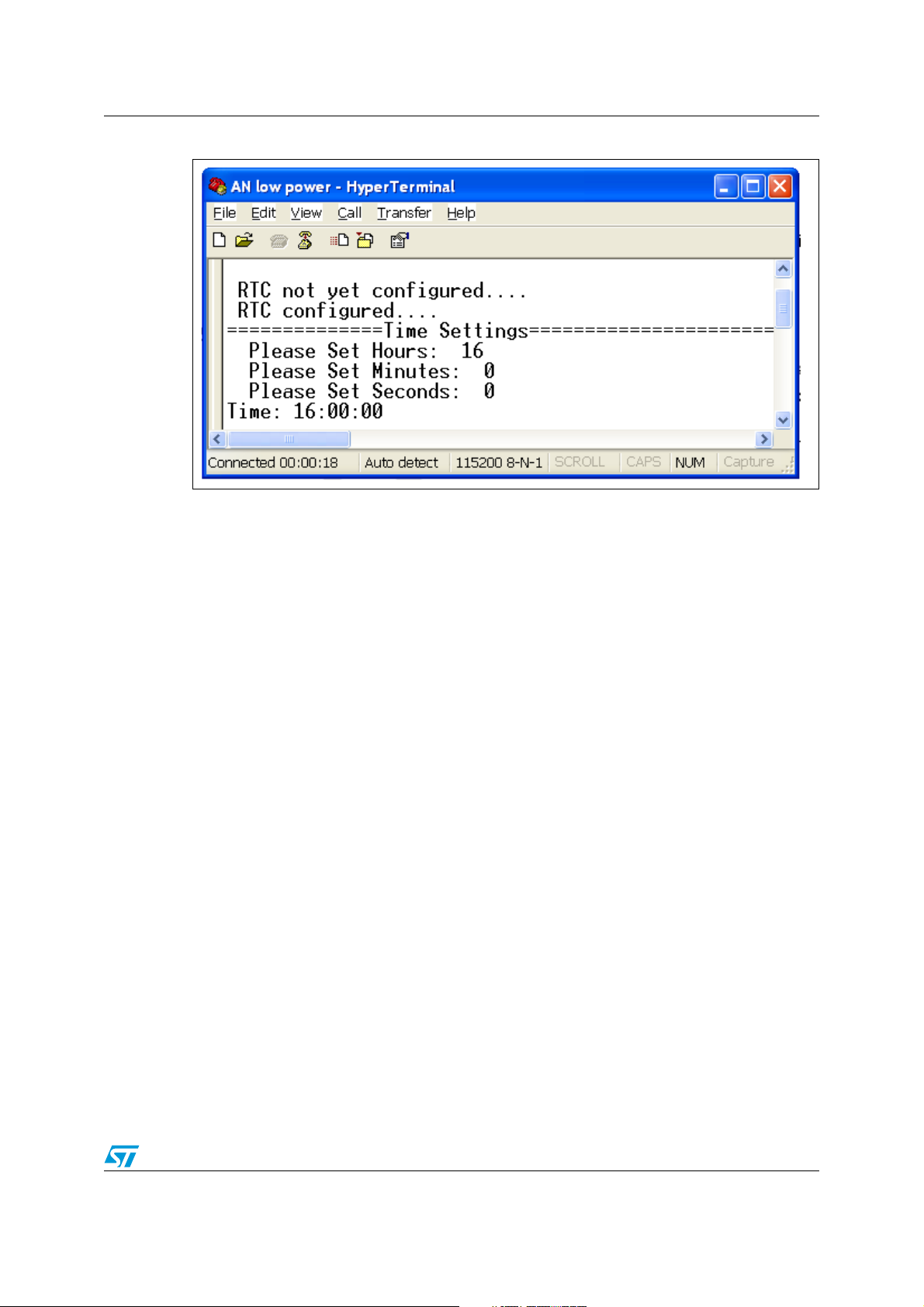
The program is a basic application that sends the time from RTC on a serial line (USART).
● At the beginning of the application, the user has to adjust the time using the
HyperTerminal for instance.
● Time is displayed on the terminal and refreshed every second. Practically, the RTC is
configured to generate an interruption every second.
● When the interruption occurs, the RTC counter is captured; the time is calculated and
sent through USART1.
Figure 6 below shows the HyperTerminal view of the time adjustment interface.
30/43 Doc ID 13922 Rev 2
Page 31
AN2629 Optimizing power consumption in your application
Figure 6. HyperTerminal time adjustment interface
Hardware environment
Use this example with STM32F10xxx evaluation board: refer to the user manual UM0426:
“STM3210B-EVAL evaluation board” to use the STM3210B-EVAL.
● The USART1 signals (RX, TX) must be connected to a DB9 connector using an RS232
transceiver.
● A null-modem female/female RS232 cable must be connected between the DB9
connector (CN6 on STM3210B-EVAL board) and the PC serial port.
● After connecting the power supply and the JTAG tools, the power consumption can be
measured by replacing Jumper JP9 by an ammeter.
Firmware description
● Launch this example with the used toolchain:
The standard tools can be used to run the example.
The .uv2 file used to launch the project with the RVMDK toolchain is contained in the
RVMDK folder.
Doc ID 13922 Rev 2 31/43
Page 32

Optimizing power consumption in your application AN2629
The .eww file, used to launch the project with the EWARM toolchain, is in the EWARM
folder.
● Configure HyperTerminal on the PC
– Word length = 8 bits
– One Stop bit
– No parity
– Baud rate = 115200 baud
– flow control: none
● Configure the firmware
In the header file (main.h) several #define can be selected to parameterize the
example. Using a #define, the user can measure by themselves the consumption
values provided in Tab le 9 .
–#define for APB1 and APB2 prescaler configuration:
#define ABP1_DIV4
#define ABP2_DIV2
#define ABP1_DIV8
#define ABP2_DIV8
–#define for peripheral selection (clock gating):
#define ALL_PERIPHERIALS_ENABLE
#define USART_ONLY
–#define for frequency selection:
#define HCLK_FREQ_72MHz /* Only with external oscillator */
#define HCLK_FREQ_8MHz
–#define for Prefetch Buffer or Half Cycle feature using:
#define PREFETCH_ON
#define HALF_CYCLE_ON
–#define for switching to Sleep mode while the application is waiting for the RTC
interrupt:
#define WFI_ON
–#define for External or Internal oscillator selection
#define HSI_ENABLE /* Use internal oscillator */
#define HSE_ENABLE /*Use external oscillator */
Caution: To reload the Flash memory after launching the low-power example, the boot pin
configuration must be changed from BOOT FLASH to BOOT RAM, and the reset button
must be pressed. This is because the debugger cannot take the hand when the
STM32F10xxx is in low-power mode.
Once this has been done, the boot pin must be configured back to BOOT FLASH.
Measurement is then started by disconnecting and reconnecting the power supply.
The power off/ power on reset sequence is necessary to avoid internal debug module
overconsumption.
32/43 Doc ID 13922 Rev 2
Page 33

AN2629 Optimizing power consumption in your application
6.3 Typical measurement results
Ta bl e 9 shows the measurements made with these examples.
Table 9. Example measurements
APB1 APB2 Peripheral Frequency Prefetch
DIV4 DIV2 ALL_ON 72 MHz ON OFF OFF HSE 33.35
DIV8 DIV8 ALL_ON 72 MHz ON OFF OFF HSE 27.85
DIV8 DIV8 USART 72 MHz ON OFF OFF HSE 25.13
DIV4 DIV2 USART 8 MHz ON OFF OFF HSE 9.23
DIV4 DIV2 USART 8 MHz OFF ON OFF HSE 6.42
DIV4 DIV2 USART 8 MHz OFF ON ON HSE 1.67
DIV4 DIV2 USART 8 MHz OFF ON ON HSI 1.09
6.4 Conclusion
To reduce power consumption, the STM32F10xxx has to be initialized with an optimized
configuration according to the used application. For this reason, the user must focus on the
application requirements and configure the STM32F10xxx accordingly.
This example shows the possible STM32F10xxx clock configurations that can be used to
optimize the power consumption of an application. They are described below:
● System and peripheral frequency
– If the application does not need to run at the maximum frequency, the user can
reduce HCLCK using the PLL or the prescaler divisor.
– The peripheral bus frequency can be reduce using the APB1 and APB2
prescalers.
Half
cycle
WFI Oscillator
Typical
consumption
at 25 °C in mA
Note: For more information on the clock tree, please refer to Figure 2 on page 15.
● Clock gating
– To optimize power consumption only peripherals used has to be clocked. That can
be done with clock gating configuration.
Note: For more information on clock gating please refer to the STM32F10xxx reference manual.
● Prefetch or half cycle features
– The prefetch feature is useful to enhance the performance. Using the prefetch
buffer in an application prevents the performance loss caused by the Flash
memory wait state.
– In applications that are not sensitive to Flash memory wait states, the half cycle
feature can be used to reduce consumption.
Doc ID 13922 Rev 2 33/43
Page 34

Optimizing power consumption in your application AN2629
Caution: Half cycle configuration is not available in combination with a prescaler on the AHB. The
clock system should be equal to the HCLK clock. This feature can therefore be used only
with a direct clock from the internal, 8 MHz RC (HSI) oscillator or with the HSE oscillator.
● Internal or external oscillator
– Using the internal oscillator instead of the external oscillator also reduces power
consumption. The maximum system clock frequency that can be attained,
however, is 64 MHz, and the accuracy is poorer than that of an external crystal
oscillator or a ceramic resonator.
Note: For more information on oscillators please refer to the STM32F10xxx reference manual.
● Sleep mode
Another way of reducing power consumption is to switch to the STM32F10xxx Sleep
mode when the application is waiting for an event or an interrupt.
This example shows the possible STM32F10xxx clock configurations that can be used to
optimize the power consumption of an application. They such as frequency selection, clock
gating, half cycle, internal oscillator and WFI mode, to optimize the power consumption of
your application.
34/43 Doc ID 13922 Rev 2
Page 35

AN2629 Using the Stop and Standby mode in battery-operated applications
7 Using the Stop and Standby mode in battery-
operated applications
7.1 Introduction
Some applications powered by a standard battery are not running all the time. For example,
industrial applications wait for information from a sensor to wake up and launch processes
and other tasks. In these applications, the microcontroller waits for an external event, and
needs to reduce its power consumption during this phase.
The Cortex-M3 core was designed to take these constrains into account and integrate
specific modes and instructions at core level.
The software provided with this application note gives two examples (WFE_Stop_Flash and
WFE_Stop_RAM) of how to use the STM32F10xxx in battery-operated applications. In
these examples the STM32F10xxx switches to the low-power mode as soon as the
application does not require processing, instead of remaining in Run mode with a low clock
frequency.
The two low-power modes are based on the Cortex-M3 core’s Deep Sleep feature and WFE
(Wait for Event) instruction.
7.2 Using Wait For Event & Stop Wait For Event
7.2.1 Context
This section describes how to use the Wait for Event instruction and the Stop mode of the
STM32F10xxx, using the firmware found in the Zip file delivered with this application note.
The firmware are available in the following folders: WFE_Stop_Flash and
WFE_Stop_RAM.
There are two projects that are exactly the same, except for the mapping in the product:
● WFE_Stop_Flash is strictly mapped in the Flash memory and runs from the Flash
memory
● WFE_Stop_Ram is downloaded in Flash memory, but some functions are remapped in
RAM at startup. How to remap code in RAM is explained in the toolset documentation.
The WFE_Stop_Flash and WFE_Stop_Ram folders contain all the subdirectories and files
that make up the core of the application example:
● inc subfolder contains the example header files
● src subfolder contains the example source files
● project subfolder contains two projects that compile the example files:
– EWARMv5: contains the project for the EWARM toolchain
– RVMDK: contains the project for the RVMDK toolchain
– RIDE: contains the project for the RIDE toolchain
Doc ID 13922 Rev 2 35/43
Page 36
Using the Stop and Standby mode in battery-operated applications AN2629
RTC alarm
ADC
WFE or STOP WFE mode
conversion
ADC
conversion
RTC alarm
PC1
ai14679
7.2.2 Detailed description
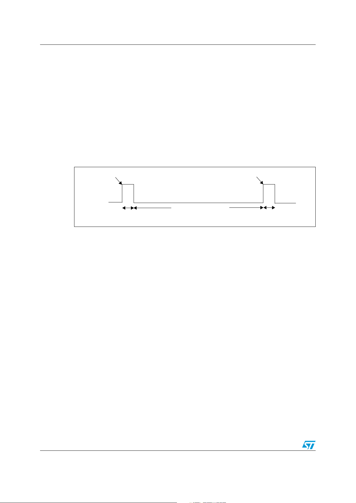
The example performs a periodic ADC conversion and stores the value in RAM buffer. It
uses Auto-Wakeup (AWU) from low-power mode as described in Section 1.2.7: Auto-
wakeup (AWU) from low-power mode on page 13.
● At the beginning, functions configure the clock, GPIO, RTC and ADC. These functions
are implemented at the end of the main.c and use the STM32F10xxx standard
peripheral library.
● The RTC is running and, each ADC conversion and storage are gated by the RTC
Alarm in the main loop.
● The RTC Alarm wakes up the STM32F10xxx from the WFE or STOP_WFE mode.
● the PC1 I/O shows the time taken by the ADC conversion and RTC Alarm register
reload.
Figure 7. WFE & STOP WFE
Hardware environment
Use this example with STM32F10xxx evaluation board: refer to the user manual UM0426:
“STM3210B-EVAL evaluation board” to use the STM3210B-EVAL.
After connecting the power supply and JTAG tools, the power consumption can be
measured by replacing Jumper JP9 by an ammeter.
Firmware description
● Launch this example with the used toolchain:
The standard tools can be used to run the example.
The .uv2 file used to launch the project with the RVMDK toolchain is contained in the
RVMDK folder.
The .eww file, used to launch the project with the EWARM toolchain, is in the EWARM
folder.
● Configure the firmware
At the beginning of the main.c, four #define can be selected to parameterize the
example:
–2 #define select the timing of the loop:
#define LOOP_20ms
#define LOOP_200ms
–2 more #define select the low-power mode:
#define WFE
#define STOP_WFE
– For the example to run, it is necessary to keep one #define of each type.
– After compiling the example, the STM32F10xxx Flash memory can be
downloaded.
36/43 Doc ID 13922 Rev 2
Page 37

AN2629 Using the Stop and Standby mode in battery-operated applications
Standby mode
conversion
ADC
conversion
RTC alarm
PC1
STM32
configuration
ADC
RTC alarm
STM32
configuration
ai14680
Caution: To reload the Flash memory after launching the low-power example, the boot pin
configuration must be changed from BOOT FLASH to BOOT RAM, and the reset button
must be pressed. This is because the debugger cannot take the hand while the
STM32F10xxx is in low-power mode.
Once this has been done, the boot pin must be configured back to BOOT FLASH.
Measurement is then started by disconnecting and reconnecting the power supply.
The power off/ power on reset sequence is necessary to avoid internal debug module
overconsumption.
7.3 Using the Standby mode in an applicative way
7.3.1 Context
This section describes how to use the Standby mode of the STM32F10xxx, using the
firmware found in the Zip file delivered with this application note. The firmware is available in
the Standby folder.
The Standby folder contains all the subdirectories and files that make up the core of the
application example:
● inc subfolder contains the example header files
● src subfolder contains the example source files
● project subfolder contains two projects that compile the example files:
– EWARMv5: contains the project for the EWARM toolchain
– RVMDK: contains the project for the RVMDK toolchain
7.3.2 Detailed description
This example performs a periodic ADC conversion and stores the value in RAM buffer. It
uses Auto-Wakeup (AWU) from low-power mode as described in Section 1.2.7: Auto-
wakeup (AWU) from low-power mode on page 13.
● At the beginning, functions configure the clock, GPIO, RTC and ADC. These functions
are implemented at the end of the main.c and use the STM32F10xxx standard
peripheral library.
● The RTC is running and the RTC Alarm wakes up the STM32F10xxx from Standby
mode.
● After each wakeup from Standby mode, the STM32F10xxx restarts from the reset state
and each ADC conversion is performed after the STM32F10xxx has been configured.
● the PC1 I/O shows the time taken by the ADC conversion and RTC Alarm register
reload but not the time taken by the STM32F10xxx to restart.
Figure 8. Standby
Doc ID 13922 Rev 2 37/43
Page 38

Using the Stop and Standby mode in battery-operated applications AN2629
Hardware environment
Use this example with STM32F10xxx evaluation board: refer to the user manual UM0426:
“STM3210B-EVAL evaluation board” to use the STM3210B-EVAL.
After connecting the power supply and JTAG tools, the power consumption can be
measured by replacing Jumper JP9 by an ammeter.
Firmware description
● Launch this example with the used toolchain:
The standard tools can be used to run the example.
The .uv2 file used to launch the project with the RVMDK toolchain is contained in the
RVMDK folder.
The .eww file, used to launch the project with the EWARM toolchain, is in the EWARM
folder.
● Configure the firmware
At the beginning of the main.c, two #define can be selected to parameterize the
example:
–2 #define select the timing of the loop:
#define LOOP_20ms
#define LOOP_200ms
– For the example to run, it is necessary to keep one #define of each type.
– After compiling the example, the STM32F10xxx Flash memory can be
downloaded.
Caution: To reload the Flash memory after launching the low-power example, the boot pin
configuration must be changed from BOOT FLASH to BOOT RAM, and the reset button
must be pressed. This is because the debugger cannot take the hand when the
STM32F10xxx is in low-power mode.
Once this has been done, the boot pin must be configured back to BOOT FLASH.
Measurement is then started by disconnecting and reconnecting the power supply.
The power off/ power on reset sequence is necessary to avoid internal debug module
overconsumption.
7.4 Typical measurement results
Ta bl e 1 0 shows the measurements made with these examples.
Table 10. Example measurements
Consumption with T
#define mode
20 ms 200 ms
WFE 1 mA 970 µA
STOP_WFE code loop running from Flash memory 58 µA 18.5 µA
STOP_WFE code loop remap in RAM 34.7 µA 16.2 µA
Standby 106 µA 14 µA
= +25 °C
A
38/43 Doc ID 13922 Rev 2
Page 39

AN2629 Using the Stop and Standby mode in battery-operated applications
7.5 Conclusion
These examples show that the Cortex-M3 integrates the very efficient Core-level
instructions for low-power applications (Sleep mode and Deepsleep mode), associated with
the low-power features of the STM32F10xxx (AWU, Stop, Low-power and Standby).
Measurements show that the trade-off between wakeup time and power consumption must
be taken into account:
● The Standby mode is more efficient in terms of power saving (3.6 µA), but the
application restarts each time from the reset states and the time to reinitialize the
application is not negligible. Indeed the initialization phase is done at 8 MHz and draws
power. If the repeated time loop is too short (20 ms), this mode is less efficient than the
Stop mode (106 µA versus 34.7 µA).
● The Stop mode is less efficient than the Standby mode in terms of low-power
consumption, but it has the advantage of keeping the context and the RAM contents. In
this example, if the repeated time loop is shorter than 200 ms, the Stop mode is more
efficient, especially if the loop code is remapped to run in RAM. If the loop lasts 200 ms
or more, however, the Standby mode becomes more advantageous.
Doc ID 13922 Rev 2 39/43
Page 40

Using the Backup domain in very low-power applications AN2629
8 Using the Backup domain in very low-power
applications
8.1 Introduction
This section describes how to use the STM32F10xxx backup registers and keep the benefit
of the low-power consumption of the Backup domain.
8.2 Using the Backup domain in an applicative way
8.2.1 Context
This section describes how to use the STM32F10xxx backup registers, using the same
firmware as the one used in Section 6.2 of this application note. It can be found in the Zip file
delivered with the application note, in the Run_Mode folder.
The Run_Mode folder contains all the subdirectories and files that make up the core of the
application example:
● inc subfolder contains the example header files
● src subfolder contains the example source files
● project subfolder contains two projects that compile the example files:
– EWARMv5: contains the project for the EWARM toolchain
– RVMDK: contains the project for the RVMDK toolchain
– RIDE: contains the project for the RIDE toolchain
8.2.2 Detailed description
The program is a basic application that sends the time from the RTC on a serial line
(USART). Every second, the time is stored into the backup registers. After a power on reset,
the contents of the backup registers are sent through the USART.
The time at which the power-off event occurred is displayed on the HyperTerminal as shown
in Figure 9.
Figure 9. HyperTerminal display of time
40/43 Doc ID 13922 Rev 2
Page 41

AN2629 Using the Backup domain in very low-power applications
For an exhaustive description see Chapter 6.2.2: Detailed description on page 30.
Hardware environment
Use this example with STM32F10xxx evaluation board: refer to the user manual UM0426:
“STM3210B-EVAL evaluation board” to use the STM3210B-EVAL.
● The USART1 signals (RX, TX) must be connected to a DB9 connector using an RS232
transceiver.
● A null-modem female/female RS232 cable must be connected between the DB9
connector (CN6 on STM3210B-EVALboard) and a PC serial port.
● RTC powered by V
the power consumption) or connect a 3 V battery on the V
: replace jumper J11 by a serial ammeter (in order to measure
BAT
pin (already mounted on
BAT
the STM3210B-EVAL board) with this jumper.
Firmware description
● Launch this example with the used toolchain:
The standard tools can be used to run the example.
The .uv2 file used to launch the project with the RVMDK toolchain is contained in the
RVMDK folder.
The .eww file, used to launch the project with the EWARM toolchain, is in the EWARM
folder.
● Configure HyperTerminal on your PC
– word length = 8 bits
– one Stop bit
– no parity
– baudrate = 115200 baud
– flow control: none
8.3 Conclusion
The Backup domain feature is used to switch off the STM32F10xxx while keeping the RTC
and the contents of ten 16-bit registers, thus saving some information useful to restart the
application. In this example, the time when the power-off event occurred is recorded. The
application context may also be kept.
Doc ID 13922 Rev 2 41/43
Page 42

Revision history AN2629
9 Revision history
Table 11. Document revision history
Date Revision Changes
5-Oct-2007 1 Initial release.
Document updated to take into account the move from the
STM32F10xxx firmware library to the STM32F10xxx standard
peripheral library V3.0.0. EWARM updated to EWARMv5.
Low-speed internal RC (LSI RC) frequency changed from 32 kHz to
40 kHz.
30-Apr-2009 2
Section 1.2: Low-power modes updated to be in line with the
STM32F10xxx reference manual.
Section 2: Clock updated.
Section 5.2.2: Detailed description updated.
Firmware description modified in Section 5.3.2: Detailed description.
Values updated in Table 9: Example measurements.
Small text changes.
42/43 Doc ID 13922 Rev 2
Page 43

AN2629
Please Read Carefully:
Information in this document is provided solely in connection with ST products. STMicroelectronics NV and its subsidiaries (“ST”) reserve the
right to make changes, corrections, modifications or improvements, to this document, and the products and services described herein at any
time, without notice.
All ST products are sold pursuant to ST’s terms and conditions of sale.
Purchasers are solely responsible for the choice, selection and use of the ST products and services described herein, and ST assumes no
liability whatsoever relating to the choice, selection or use of the ST products and services described herein.
No license, express or implied, by estoppel or otherwise, to any intellectual property rights is granted under this document. If any part of this
document refers to any third party products or services it shall not be deemed a license grant by ST for the use of such third party products
or services, or any intellectual property contained therein or considered as a warranty covering the use in any manner whatsoever of such
third party products or services or any intellectual property contained therein.
UNLESS OTHERWISE SET FORTH IN ST’S TERMS AND CONDITIONS OF SALE ST DISCLAIMS ANY EXPRESS OR IMPLIED
WARRANTY WITH RESPECT TO THE USE AND/OR SALE OF ST PRODUCTS INCLUDING WITHOUT LIMITATION IMPLIED
WARRANTIES OF MERCHANTABILITY, FITNESS FOR A PARTICULAR PURPOSE (AND THEIR EQUIVALENTS UNDER THE LAWS
OF ANY JURISDICTION), OR INFRINGEMENT OF ANY PATENT, COPYRIGHT OR OTHER INTELLECTUAL PROPERTY RIGHT.
UNLESS EXPRESSLY APPROVED IN WRITING BY AN AUTHORIZED ST REPRESENTATIVE, ST PRODUCTS ARE NOT
RECOMMENDED, AUTHORIZED OR WARRANTED FOR USE IN MILITARY, AIR CRAFT, SPACE, LIFE SAVING, OR LIFE SUSTAINING
APPLICATIONS, NOR IN PRODUCTS OR SYSTEMS WHERE FAILURE OR MALFUNCTION MAY RESULT IN PERSONAL INJURY,
DEATH, OR SEVERE PROPERTY OR ENVIRONMENTAL DAMAGE. ST PRODUCTS WHICH ARE NOT SPECIFIED AS "AUTOMOTIVE
GRADE" MAY ONLY BE USED IN AUTOMOTIVE APPLICATIONS AT USER’S OWN RISK.
Resale of ST products with provisions different from the statements and/or technical features set forth in this document shall immediately void
any warranty granted by ST for the ST product or service described herein and shall not create or extend in any manner whatsoever, any
liability of ST.
ST and the ST logo are trademarks or registered trademarks of ST in various countries.
Information in this document supersedes and replaces all information previously supplied.
The ST logo is a registered trademark of STMicroelectronics. All other names are the property of their respective owners.
© 2009 STMicroelectronics - All rights reserved
STMicroelectronics group of companies
Australia - Belgium - Brazil - Canada - China - Czech Republic - Finland - France - Germany - Hong Kong - India - Israel - Italy - Japan -
Malaysia - Malta - Morocco - Philippines - Singapore - Spain - Sweden - Switzerland - United Kingdom - United States of America
www.st.com
Doc ID 13922 Rev 2 43/43
 Loading...