

Page 1

AN2626
Application note
MOSFET body diode recovery mechanism in a phase-shifted
ZVS full bridge DC/DC converter
Introduction
The ZVS exploits the parasitic circuit elements to guarantee zero voltage across the
switching device before turn on, eliminating hence any power losses due to the
simultaneous overlap of switch current and voltage at each transition [1].
In order to allow the ZVS condition, the intrinsic body diode of the MOSFET has to conduct;
in no or low load operation the extremely low reverse voltage, could be not sufficient to
guarantee the reverse recovery charge sweep out before turning off the MOSFET. Hence,
the body diode could be stressed by high dv/dt that latching the parasitic internal bipolar
transistor brings the MOSFET to the failure.
In the market of power applications like telecom power supply, main frame computer-server,
welding and steel cutting, the demand of power density is growing each year. Increasing
power density means reducing component counts, power losses, heat-sink and reactive
component size. The alternative to the hard switched full bridge, typical topology for these
applications, was the phase-shifted zero voltage switching (ZVS) full bridge. This ZVS
technique guarantees zero voltage across the switching device before turn on, eliminating
hence any power losses due to the simultaneous overlap of switch current and voltage at
each transition.
By this switching technique also at high frequencies, the switching losses are low; hence it
allows the reduction of the components reactive size only. Obviously, by having lower losses
lower heat-sink size is allowed. Furthermore, by avoiding the hard-switching condition the
EMI/RFI noise is reduced.
The zero voltage condition occurs by the intrinsic MOSFET body diode conduction; an
extremely low reverse voltage, occurring at no or low load operation, which could be not
sufficient to guarantee the reverse recovery charge sweep out before turning off the
MOSFET. In this condition high dv/dt values could turn on the intrinsic bipolar and destroy
the MOSFET.
The deep studies of these failure mechanisms have led STMicroelectronics to design new
technology in order to develop MOSFETs really suitable for high power phase-shifted ZVS
applications. In this technical note we will investigate the possible triggering on of the
internal parasitic bipolar.
September 2007 Rev 1 1/13
www.st.com
Page 2

Contents AN2626
Contents
1 Topology description . . . . . . . . . . . . . . . . . . . . . . . . . . . . . . . . . . . . . . . . 4
2 MOSFET body diode recovery . . . . . . . . . . . . . . . . . . . . . . . . . . . . . . . . . 7
3 Observations . . . . . . . . . . . . . . . . . . . . . . . . . . . . . . . . . . . . . . . . . . . . . . 10
4 References . . . . . . . . . . . . . . . . . . . . . . . . . . . . . . . . . . . . . . . . . . . . . . . . 12
5 Revision history . . . . . . . . . . . . . . . . . . . . . . . . . . . . . . . . . . . . . . . . . . . 12
2/13
Page 3

AN2626 List of figures
List of figures
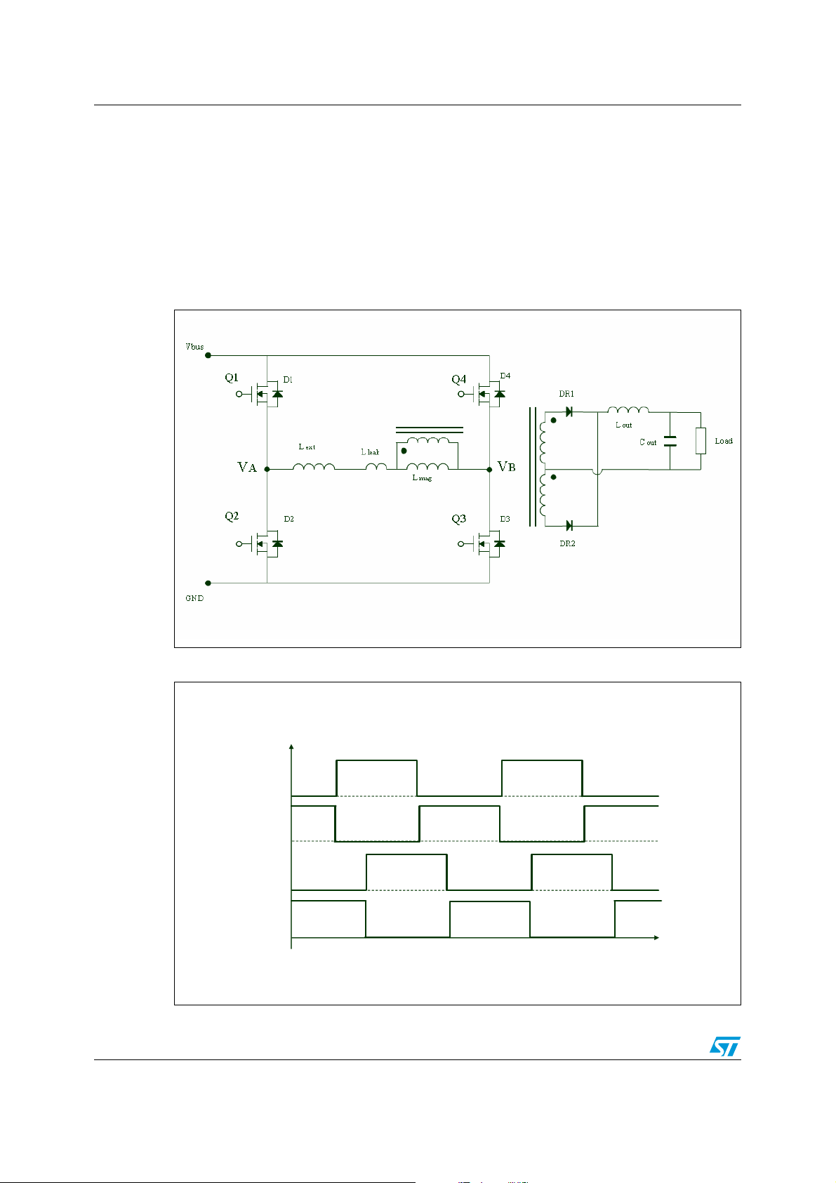
Figure 1. Phase-shifted ZVS full bridge circuit. . . . . . . . . . . . . . . . . . . . . . . . . . . . . . . . . . . . . . . . . . . 4
Figure 2. Switching sequence in a P-S ZVS FB converter DC/DC . . . . . . . . . . . . . . . . . . . . . . . . . . . 4
Figure 3. Typical waveforms in a P-S ZVS FB converter DC/DC . . . . . . . . . . . . . . . . . . . . . . . . . . . . 5
Figure 4. Current flow into the parallel body diode-channel MOSFET . . . . . . . . . . . . . . . . . . . . . . . . 7
Figure 5. Current flow into the parallel body diode-channel MOSFET. . . . . . . . . . . . . . . . . . . . . . . . . 8
Figure 6. Current flow into the channel MOSFET (first quadrant) . . . . . . . . . . . . . . . . . . . . . . . . . . . . 8
Figure 7. Current flow due to the reverse recovery of the body diode . . . . . . . . . . . . . . . . . . . . . . . . 9
Figure 8. Comparison between standard and fast diode technology . . . . . . . . . . . . . . . . . . . . . . . . . 10
Figure 9. A typical leading leg MOSFET waveforms . . . . . . . . . . . . . . . . . . . . . . . . . . . . . . . . . . . . . 11
Figure 10. A typical lagging leg MOSFET waveforms . . . . . . . . . . . . . . . . . . . . . . . . . . . . . . . . . . . . . 11
3/13
Page 4
Topology description AN2626
1 Topology description
The basic circuit of the phase-shifted converter is composed by four switches; two for each
"leg".
The switches, labeled Q1 through Q4 in the Figure 1 are shunted by their intrinsic body
diode (D1 through D4) and intrinsic output capacitance (C1 through C4), shown separately
in order to clarify their role in the global functioning.
Figure 1. Phase-shifted ZVS full bridge circuit
Figure 2. Switching sequence in a P-S ZVS FB converter DC/DC
Vgate
Vgate
Q1
Q1
Q2
Q2
Q3
Q3
Q4
Q4
4/13
t
t
Page 5

AN2626 Topology description
● Transition t
0-t1
From the Figure 3, at t0 Q1 and Q3 are in on state and on the primary side there is an
energy equal to:
Equation 1
1
E
t0t1–
E
–
magEoutput reflected–
-- -
L
leakLres
2
+()I
() NI
magt0
()+()⋅+=
outt0
Instantly, at t
the switch Q1 is turned off and the resonant transition begins. The primary
0
current continues to flow, with a like-linear shape (since the current is forced by the output
inductor) using the charge stored in the switch output capacitance C2. Simultaneously, the
primary current will charge the output capacitance C1 of Q1 from essentially 0 V to the
supply voltage V
, and will discharge the output capacitance C2 from Vdd to zero. The
dd
transition finishes when the Q2 source voltage exceeds the Q2 drain voltage sufficiently to
directly bias the internal body diode D2.
● Freewheeling t
1-t2
Now D3 is directly biased and the output inductor freewheels. The voltage across the switch
Q2 is equal to the drop on its internal body diode D2 hence the ZVS condition is verified.
The switch Q3 is turned on and the current, flowing through the primary side, now is shared
between the body diode D2 and the channel of MOSFET Q2. During the freewheeling state
both output rectifier diodes are forward biased, and hence the reflected voltage to the
primary is null.
Figure 3. Typical waveforms in a P-S ZVS FB converter DC/DC
V
A
V
A
V
B
V
B
V
A -VB
V
A -VB
I
PI
I
PI
t
t
0t2t4
● Transition t
2-t4
0t2t4
t
1
t
1
t
3
t
3
t
5
t
5
t
t
The switch Q3 is turned off, the energy available to complete the transition is:
Equation 2
1
E
t2t4–
-- -
L
leakLres
2
+()I
() NI
magt2
()+()⋅=
outt2
It is much lower than it was in the lead leg, since the magnetizing and output inductance do
not contribute [4]. For this reason it is easier to miss the ZVS condition. If the energy stored
5/13
Page 6

Topology description AN2626
is enough, the current will continue to flow into the output capacitances C3 and C4. During
the first period the voltage is applied across the leakage and external inductors added in
series to the theoretical primary winding of the transformer. The voltage across the
theoretical primary winding of the transformer will remain zero, and both output diodes will
conduct, until the current flowing through the leakage and external inductors will change
direction and reach the reflected output current (t
● Power transfer t
4-t5
3-t4
period).
Once the output diode is turned on, the power is transferred from primary to the secondary
side of transformer. When the primary current reaches the expected value the circuit is in a
condition similar to that reported in the step 1.
6/13
Page 7

AN2626 MOSFET body diode recovery
2 MOSFET body diode recovery
The cross section of a MOSFET device, illustrated in Figure 4, shows an intrinsic diode
between body and drain, that is the base-collector junction of the "parasitic" a NPN bipolar
transistor source-body-drain. In no or low load conditions this transistor could be turned on
and hence brings the MOSFET to the failure, by short circuiting drain and source while high
voltages are applied among them. In order to understand this possible failure we must
investigate the freewheeling and the ZVS steps. During step 2 the current freewheels into
the body-drain diode D2 (see Figure 4); since this is directly biased carriers are injected in
the N- epi (holes) and P body (electrons) regions of the device. Once Q2 is turned on, a
portion of the total current flows through the channel, the parasitic JFET, and the epi region:
the MOSFET is conducting in the third quadrant (see Figure 5). When the transformer
current changes direction the MOSFET Q3 conducts into the first quadrant (see Figure 6).
The internal body diode D2 now is reverse biased; since it is in parallel with the low
resistance channel regions its effective reverse voltage is low. This causes a slow minority
carriers extraction, especially from the N- region, since the holes have lower mobility than
the electron one. Obviously at low load operation the current flowing through the channel
MOSFET is much lower and so is the drop voltage; in this condition the body diode needs
more time to complete the reverse recovery, but the powering period is very short and could
not be sufficient to remove the minority carriers in the P-N junction.
Figure 4. Current flow into the parallel body diode-channel MOSFET
7/13
Page 8

MOSFET body diode recovery AN2626
Figure 5. Current flow into the parallel body diode-channel MOSFET
When the Q2 MOSFET is turned off D2 should have yet completely removed its minority
carriers, see from both P+ and N- regions, otherwise the high reverse voltage (due to Q1
turning on) results in a fast removal of these carriers. Minority carriers in the N- region are
swept towards the P+ body region and this rapid displacement results in a significant current
flowing through the P+ body.
Figure 6. Current flow into the channel MOSFET (first quadrant)
8/13
Page 9

AN2626 MOSFET body diode recovery
In normal condition the source and body regions (that is the emitter and the base of the
parasitic bipolar) are shorted via upper source metallization, but by flowing a significant
current into the body region below the source region (see Figure 7), the intrinsic resistance
of this region (shown as Rb) could divert a sufficient current portion able to trigger on the
parasitic bipolar; it means creating a short circuit between drain and source pins thus,
destroying the device.
Figure 7. Current flow due to the reverse recovery of the body diode
Hence, in order to overcome the previous problems, a MOSFET should have some
characteristics:
● The intrinsic body diode with low Trr and low Qrr;
● Ruggedness to the stress due to the trigger on of the parasitic bipolar.
To meet the need related to the body diode a new technology has been developed. The new
FD (fast diode) MOSFET has straightforward advantages in terms of Trr, Qrr, Irm and
ruggedness in dv/dt.
9/13
Page 10

Observations AN2626
3 Observations
Choosing to use fast diode technology MOSFETs is a good choice. STMicroelectronics has
developed the new Fast diode MD mesh generation that shows excellent performance in
these types of topologies. These device families guarantee operation in safe conditions, so
far from the triggering on of the parasitic bipolar, so that they are very suitable for the full
bridge phase-shift ZVS topologies.
In order to understand these advantages we have compared a standard MOSFET versus a
FD MOSFET.
The FD technology device has a lower Qrr than the standard device; meaning that when the
diode is reverse biased by the drop voltage on the channel MOSFET, very low in low load
condition, it will be faster to complete the recovery and so when it will highly reverse biased
by the turn on of the switch in the its same leg it will work in a much more safe condition in
term of dv/dt stress (see Figure 8).
Figure 8. Comparison between standard and fast diode technology
Table 1. Measured dynamic electrical parameters of the devices compared
Irm Trr Qrr
Device
Standard STW20NM60 25 390 5
Fast diode
STW20NM60FD
(Di/Dt=100A µs, Isd=20 A, Vdd=100 V, Tj=25°C)
(A) (nS) (µC)
16 240 1.8
As you can see the ST fast diode technology MOSFET works better, keeping the overall
system in a more safe condition.
10/13
Page 11

AN2626 Observations
The fast diode device has worked properly in the application and has shown good
performances; report some pictures related to a 1.5 kW DC/DC converter captured on test
bench (Figure 9 and Figure 10).
Figure 9. A typical leading leg MOSFET waveforms
Figure 10. A typical lagging leg MOSFET waveforms
11/13
Page 12

References AN2626
4 References
1. L. Saro, et al., "High-Voltage MOSFET Behavior in Soft-Switching Converter: Analysis
and Reliability Improvements," International Tel-communication Conference, San
Francisco, 1998.
2. Alexander Fiel and Thomas Wu International Rectifier Applications Department El
Segundo, CA 90245, USA "MOSFET Failure Modes in the Zero-Voltage-Switched FullBridge Switching Mode Power Supply Applications"
3. Sampat Shekhawat, Mark Rinehimer and Bob Brockway Discrete Power Group,
Fairchild Semiconductor AN-7536 "FCS Fast Body Diode MOSFET for Phase-Shifted
ZVS PWM Full Bridge DC/DC Converter"
4. Laszlo Balogh, "Design review:100 W, 400 kHz, DC/DC converter with current doubler
synchronous rectification achieves 92% efficiency"
5 Revision history
Table 2. Document revision history
Date Revision Changes
21-Sep-2007 1 Initial release
12/13
Page 13

AN2626
Please Read Carefully:
Information in this document is provided solely in connection with ST products. STMicroelectronics NV and its subsidiaries (“ST”) reserve the
right to make changes, corrections, modifications or improvements, to this document, and the products and services described herein at any
time, without notice.
All ST products are sold pursuant to ST’s terms and conditions of sale.
Purchasers are solely responsible for the choice, selection and use of the ST products and services described herein, and ST assumes no
liability whatsoever relating to the choice, selection or use of the ST products and services described herein.
No license, express or implied, by estoppel or otherwise, to any intellectual property rights is granted under this document. If any part of this
document refers to any third party products or services it shall not be deemed a license grant by ST for the use of such third party products
or services, or any intellectual property contained therein or considered as a warranty covering the use in any manner whatsoever of such
third party products or services or any intellectual property contained therein.
UNLESS OTHERWISE SET FORTH IN ST’S TERMS AND CONDITIONS OF SALE ST DISCLAIMS ANY EXPRESS OR IMPLIED
WARRANTY WITH RESPECT TO THE USE AND/OR SALE OF ST PRODUCTS INCLUDING WITHOUT LIMITATION IMPLIED
WARRANTIES OF MERCHANTABILITY, FITNESS FOR A PARTICULAR PURPOSE (AND THEIR EQUIVALENTS UNDER THE LAWS
OF ANY JURISDICTION), OR INFRINGEMENT OF ANY PATENT, COPYRIGHT OR OTHER INTELLECTUAL PROPERTY RIGHT.
UNLESS EXPRESSLY APPROVED IN WRITING BY AN AUTHORIZED ST REPRESENTATIVE, ST PRODUCTS ARE NOT
RECOMMENDED, AUTHORIZED OR WARRANTED FOR USE IN MILITARY, AIR CRAFT, SPACE, LIFE SAVING, OR LIFE SUSTAINING
APPLICATIONS, NOR IN PRODUCTS OR SYSTEMS WHERE FAILURE OR MALFUNCTION MAY RESULT IN PERSONAL INJURY,
DEATH, OR SEVERE PROPERTY OR ENVIRONMENTAL DAMAGE. ST PRODUCTS WHICH ARE NOT SPECIFIED AS "AUTOMOTIVE
GRADE" MAY ONLY BE USED IN AUTOMOTIVE APPLICATIONS AT USER’S OWN RISK.
Resale of ST products with provisions different from the statements and/or technical features set forth in this document shall immediately void
any warranty granted by ST for the ST product or service described herein and shall not create or extend in any manner whatsoever, any
liability of ST.
ST and the ST logo are trademarks or registered trademarks of ST in various countries.
Information in this document supersedes and replaces all information previously supplied.
The ST logo is a registered trademark of STMicroelectronics. All other names are the property of their respective owners.
© 2007 STMicroelectronics - All rights reserved
STMicroelectronics group of companies
Australia - Belgium - Brazil - Canada - China - Czech Republic - Finland - France - Germany - Hong Kong - India - Israel - Italy - Japan -
Malaysia - Malta - Morocco - Singapore - Spain - Sweden - Switzerland - United Kingdom - United States of America
www.st.com
13/13
 Loading...