

Page 1

AN2618
Application note
eTPU host interface
Introduction
The eTPU is the new generation of Time Processing Unit (TPU). Besides the hardware
enhancement, significant improvements have been made to the accompanying software
development tools; these tools make the enhanced Time Processing Unit (eTPU) easy to
use. A high level language (C) compiler has been developed to allow the user to program
the eTPU by using C language instead of microcode.
To program the eTPU effectively, the programmer still needs to have a clear understanding
of how the eTPU hardware works. Coding in C, the programmer can focus more on the
application logic and leave the mechanics of the eTPU programming to the compiler (i.e.,
register usage and tracking, parameter packing, micro-instruction packing, etc.). With the
help of the eTPU simulator and debugger, eTPU software can be developed much like the
software for the host CPU. Productivity of software development can be significantly
improved.
The introduction of the eTPU C compiler also changes the way the host interfaces to the
eTPU functions. With the help of the compiler, the same symbol can be referenced by the
both eTPU and host software. The host software can interface with eTPU functions via API
functions, instead of accessing physical memory locations and registers. For each eTPU
function, a host interface API function can now be developed as a part of the eTPU C
program. The host application can call these API functions to interface with the eTPU. The
references to these API functions and symbols for parameters are resolved at compile time.
The implementation details of the eTPU functions are hidden from the host application. This
design improves the flexibility of the eTPU functions’ implementation and the portability of
the host application code. This application note discusses how to build the host interface for
eTPU functions.
This application note shows how to build the host interface to access eTPU functions. The
eTPU PWM driver is used as an example to illustrate what the host needs to do to configure
eTPU module, channel and initialize PWM function. The application note also describes the
details of how to export eTPU software information to the host compiler. The working code
example is presented in the Appendix. The user can compile both host and eTPU code,
then download to actual hardware for testing.
September 2007 Rev 1 1/23
www.st.com
Page 2

Contents AN2618
Contents
1 Overview . . . . . . . . . . . . . . . . . . . . . . . . . . . . . . . . . . . . . . . . . . . . . . . . . . 3
2 eTPU and host interface hardware . . . . . . . . . . . . . . . . . . . . . . . . . . . . . 4
3 Host interface software . . . . . . . . . . . . . . . . . . . . . . . . . . . . . . . . . . . . . . 5
3.1 Initialization overview . . . . . . . . . . . . . . . . . . . . . . . . . . . . . . . . . . . . . . . . . 5
3.2 eTPU module initialization . . . . . . . . . . . . . . . . . . . . . . . . . . . . . . . . . . . . . 5
3.3 eTPU channel initialization . . . . . . . . . . . . . . . . . . . . . . . . . . . . . . . . . . . . . 7
3.4 eTPU function initialization . . . . . . . . . . . . . . . . . . . . . . . . . . . . . . . . . . . . . 7
3.5 eTPU and host interactive control . . . . . . . . . . . . . . . . . . . . . . . . . . . . . . . 8
4 Software integration . . . . . . . . . . . . . . . . . . . . . . . . . . . . . . . . . . . . . . . . . 9
5 Conclusion . . . . . . . . . . . . . . . . . . . . . . . . . . . . . . . . . . . . . . . . . . . . . . . . 10
Appendix A Code example 1.main.c . . . . . . . . . . . . . . . . . . . . . . . . . . . . . . . . . . . 11
Appendix B Code example 2.etpu_PWMControl.h . . . . . . . . . . . . . . . . . . . . . . . 12
Appendix C Code example 3.etpuc_pwm.c . . . . . . . . . . . . . . . . . . . . . . . . . . . . . 13
Appendix D Code example 4.etpuc_image.h . . . . . . . . . . . . . . . . . . . . . . . . . . . . 16
Appendix E Code example 5.etpu_pwm_auto.h . . . . . . . . . . . . . . . . . . . . . . . . . 17
Appendix F Code example 6.utility.c . . . . . . . . . . . . . . . . . . . . . . . . . . . . . . . . . . 18
Appendix G Code example 7.etpu_pwm.c . . . . . . . . . . . . . . . . . . . . . . . . . . . . . . 20
6 Revision history . . . . . . . . . . . . . . . . . . . . . . . . . . . . . . . . . . . . . . . . . . . 22
2/23
Page 3

AN2618 Overview
1 Overview
Host interface software adds another layer of abstraction between the host CPU and eTPU.
The host interface API functions hide the complexity of the interaction between the host
CPU and eTPU, providing a simple interface for host applications. Ideally, every eTPU
function shall have one or more host interface API functions.
The interface software between host and eTPU facilitates three major tasks:
1. eTPU hardware initialization – configure eTPU peripheral hardware
2. eTPU function initialization – pass initial parameters and initiate function execution
3. eTPU function run time interactive control – update function parameters and handle
handshaking
Once the eTPU peripheral and eTPU functions are initialized, each eTPU function can start
to execute with initial function parameters. The host interface API functions need to be
provided for interactive control (i.e. parameters updating and control mode changing etc.).
To update the parameter or change control mode, the host is responsible for passing
updated parameters to the eTPU functions, and then informing the eTPU that the function
parameters have changed. If a coherent change of function parameters is required, the logic
has to be built in the eTPU functions to ensure the coherency. For some eTPU functions, the
interaction between host and eTPU is an essential part of the operation. In both host and
eTPU software, the logic is needed to handle the handshaking between host and eTPU. The
interaction between the eTPU and host can be encapsulated in the host interface API
functions.
The host code and eTPU code are compiled by different compilers. The host compiler is
normally used to build a single code image for both host and eTPU. In order to build eTPU
code and host code together, the eTPU software building information (i.e. eTPU code
image) has to be exported to the host compiler. The symbol information has to be exported
from the eTPU compiler to the host compiler as well. For the Byte Craft eTPU compiler, the
mechanism is implemented as a set of host interface macros. In the eTPU code, these
macros are inserted to generate proper executable and symbol information for the host
compiler.
The host interface design process is illustrated in the eTPU PWM driver examples in the
Appendices.
3/23
Page 4
eTPU and host interface hardware AN2618
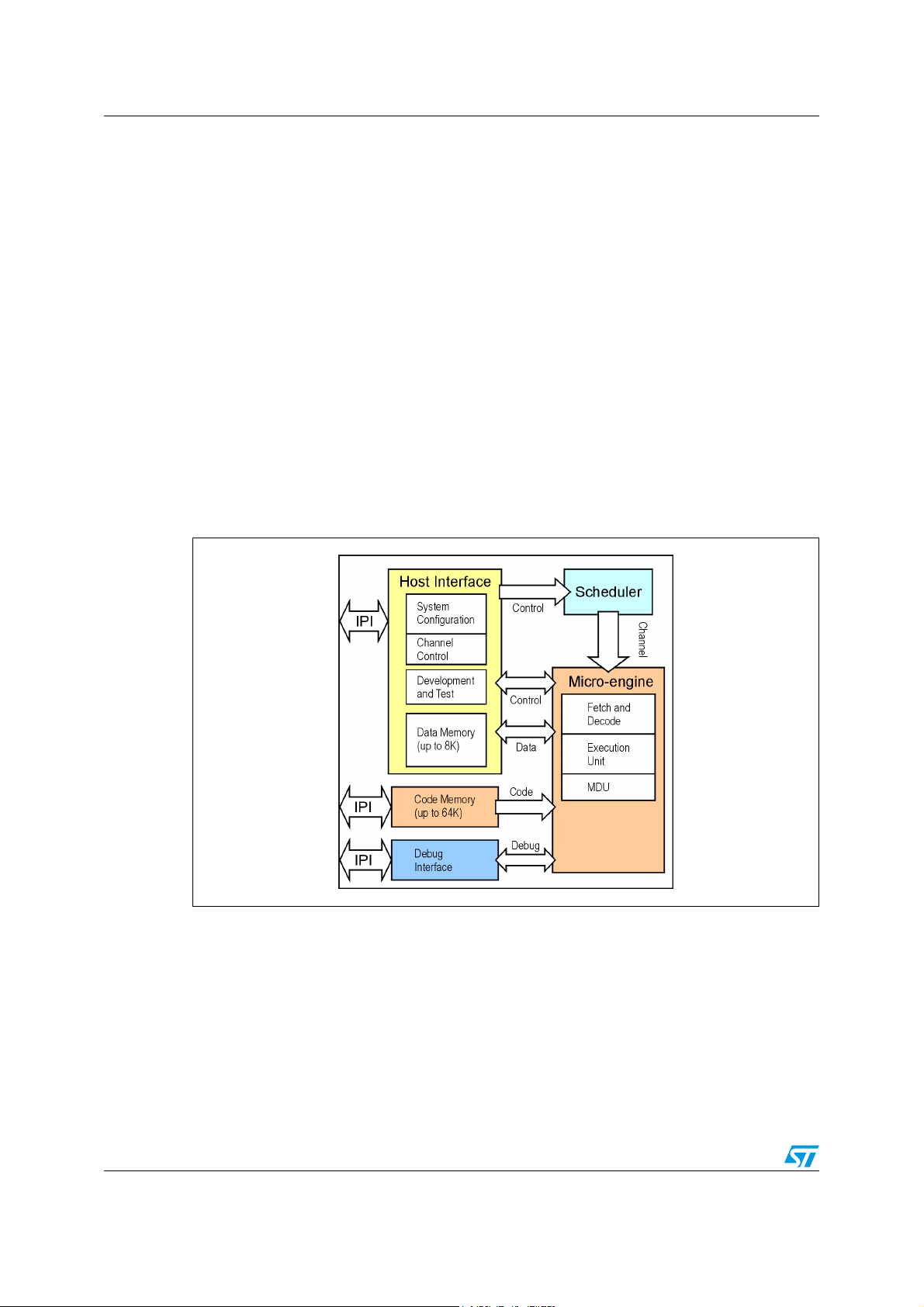
2 eTPU and host interface hardware
The host interface hardware for the eTPU is shown in Figure 1. The host and eTPU can
communicate to each other via event or by data.
The host has access to all eTPU host interface registers. When the host wants the eTPU’s
services, it can issue the host service request (HSR) by writing the eTPU channel control
registers. Once the host service request is acknowledged, a thread of eTPU code
associated with this HSR is activated for execution. The eTPU code in the thread
implements the functions requested by the host. When eTPU needs the host service, it can
issue the interrupt request or DMA data transfer request, or generate a global exception.
The events handling logic is needed in the host software to provide services to the eTPU
corresponding to these requests.
The eTPU code memory (RAM) and data memory (RAM) are accessible by both host and
eTPU. eTPU code memory stores the eTPU executable binary image. At the power up
initialization, following the defined sequences, the host transfers the eTPU code stored in
the flash memory to the eTPU code memory. During the execution, the eTPU micro-engine
fetches the micro-instructions from the code memory.
Figure 1. eTPU host interface hardware
The eTPU data memory is implemented by using tri-port RAM. It provides for data sharing
between the host and eTPU engines. Both host and eTPU can read and write the eTPU
data memory in any data size (8, 16, 24, and 32 bit). Since the eTPU data bus is 24 bits
wide, it is best to pack together a data word with an 8 bit value and a 24 bit value in order to
reduce data memory utilization. To reduce the overhead of packing and unpacking the data,
a virtual mirror memory space of the normal eTPU data memory has been created. The
virtual memory space is called Parameter Sign Extension (PSE) memory space. When the
host reads the 32-bit data from the PSE memory space, it will return the sign extended 24bit data. The conversion is needed if the 24-bit data is unsigned. Similarly, when the host
writes the 32-bit data to the eTPU PSE memory, only the three least significant bytes will be
written to the eTPU data memory. The most significant byte is untouched.
4/23
Page 5

AN2618 Host interface software
3 Host interface software
The function partition between the application software and low-level driver is defined during
the software architecture design. To make the software portable, the application software is
normally designed to interface with the low-level driver via abstracted interface APIs. The
host interface of the eTPU functions should be designed such that the implementation of the
low-level driver is hidden from the application software.
Once the application software interface to the low-level driver is defined, the functionality of
the low-level driver can be partitioned between host CPU and eTPU. The eTPU interface
software running on the host CPU is an integral part of the low-level driver. It handles the
details of the interaction between host and eTPU.
The eTPU code and host interface code are compiled by two different compilers. In order to
resolve the eTPU code symbol reference in the host code, it is necessary to export the
symbolic information from the eTPU compiler to the host compiler. Similarly, to build a single
executable image, it is necessary to export eTPU code image to the host compiler. Several
types of information are exported from eTPU_C through host interface files, generated from
#pragma write statements during compilation. For detailed information on #pragma
write, see the eTPU_C documentation.
An example of application software and low-level driver partition is shown in Appendix A on
page 11.
3.1 Initialization overview
The eTPU initialization is an important part of the host interface. At the power up, the host
has to configure the eTPU peripheral properly before the eTPU function can be executed.
The eTPU initialization process is accomplished by both host CPU and eTPU. During the
initialization, the functional partition between host CPU and eTPU is as follows:
Host responsibility:
● eTPU module initialization
● eTPU channel configuration
● Providing initial eTPU function parameters
● Initiating the eTPU function execution
eTPU responsibility:
● Responding to the HSR
● Transitioning into the initialization state
The eTPU initialization can be broken down into three steps: eTPU module initialization,
eTPU channel initialization and eTPU function initialization. The following sections discuss
the interface design and the data exchange between host CPU and eTPU for each step of
initialization.
3.2 eTPU module initialization
At the power up initialization, the eTPU peripheral hardware is configured by the host. The
eTPU module initialization includes the following steps:
5/23
Page 6

Host interface software AN2618
1. Initialize eTPU global registers
– eTPU MISC Compare Register (ETPU_MISCCMPR)
– eTPU Module Configuration Register (ETPU_MCR)
– eTPU Time Base Configuration Register (ETPU_TBCR)
– eTPU STAC Bus Configuration Register (ETPU_STACR)
– eTPU Engine Configuration Register (ETPU_ECR)
2. Load eTPU code from flash memory to eTPU code RAM
3. Copy initial values of eTPU code global variables to eTPU data memory
Most of the information required to configure the eTPU global registers are not dependent
on the eTPU software implementation (i.e., time base, clock frequency, entry table address,
etc.). The configuration information is determined during the host peripheral configuration
and resource allocation. Only the MISC value depends on the actual eTPU software
implementation; it has to be exported to the host program after the eTPU code is compiled.
The eTPU_C compiler provides a macro (::ETPUmisc) to calculate the MISC value of the
eTPU code image (see Appendix C on page 13).
The eTPU code image is generated when the eTPU C program is compiled. To use this
code in the host program, the eTPU code image can be exported as an array of constant
values. The eTPU_C compiler provides a macro (::ETPUcode) to generate and export the
eTPU code image (see Appendix C on page 13). The eTPU code image constant array is
suitable to be included in the host source code. The host compiler locates the eTPU code
image array in the flash memory at host source code compile time. Since the eTPU microengine can only fetch micro-instructions out of eTPU code memory (RAM), at the power up
initialization, the eTPU code image has to be loaded to eTPU code memory.
As it is in the standard C syntax, when the eTPU code is compiled, the global variables are
allocated to the eTPU data memory and the initial values are assigned to the corresponding
memory locations. The standard C syntax requires that all global variables are declared
outside of any function. For eTPU, this means that all global variables have to be declared
outside of any execution thread. Since only the code in a thread can be executed on eTPU,
the global variable initial value assignment statements will not be executed. The global
variables cannot be initialized in the eTPU code; they must be initialized by the host.
The software statements have to be added to the host code to initialize the eTPU global
variables. The initialization values have to be exported from the eTPU compiler to host
compiler. The eTPU_C compiler provides a macro (::ETPUglobalimage) to capture initial
values for all global variables and exports them as a constant array (Appendix D on page
16). At power up initialization, the global variable initial values are loaded to the eTPU data
memory for global variables.
The host interface macros have to be added to the eTPU code in #pragma write
statements to export the eTPU software information to the host compiler (Appendix C on
page 13). These statements will generate header files that contain the MISC value, eTPU
code image and global variable memory image (Appendix D on page 16).
The software for the eTPU module initialization can be encapsulated in an API function. An
example of the eTPU module initialization function implementation is provided in Appendix F
on page 18 (mc_etpu_init()).
6/23
Page 7

AN2618 Host interface software
3.3 eTPU channel initialization
After the eTPU module is configured, each channel on the eTPU module can be configured.
eTPU channel initialization includes the following tasks:
1. eTPU channel configuration registers initialization
– Assign eTPU function to a channel
– Setup channel priority
– Configure interrupt/DMA/Output enable
– Select eTPU function entry table encoding
– Assign the function frame to a channel
2. eTPU channel status control register initialization
– Set up eTPU function mode
The eTPU channel assignment and the channel priority determination are a part of the host
software architecture design. They are independent of the eTPU functions implementation.
The information for the configuration is provided by the host software design.
During the channel initialization, a section of eTPU data memory is assigned to each
channel. This memory section is called the “function frame”. The function frame contains all
the function parameters and static local variables used by the eTPU function. The starting
address of the function frame is assigned to the channel at initialization. The function frame
assignment can be static or dynamic. Dynamic allocation assigns the function frame to the
channel based on the next available memory space. The availability of the eTPU data
memory depends on the number of functions that have been assigned and the number of
parameters the function is using. Dynamic allocation can reduce the eTPU data memory
consumption by minimizing unused memory ‘holes’. To allocate the function frame
dynamically, the host must know the function frame consumption by a particular eTPU
function. The eTPU_C compiler provides a macro (::ETPUram) to report the number of
parameters and static local variables used by a function at compile time (Appendix C on
page 13).
The eTPU function table entry encoding, interrupt enable, DMA enable, output enable,
output polarity, and function mode are constants specific to the eTPU function software
implementation. It is a good practice to define them only once in the eTPU code and export
the configuration information at compile time.
Once the host interface macros are added to the eTPU code (Appendix C on page 13), the
#pragma write statements will generate a header file that contains all the eTPU function
configuration and software symbol information at compile time (Appendix E on page 17).
The header file can be included in the host interface code to resolve symbol references.
3.4 eTPU function initialization
The eTPU function initialization is the last step of the eTPU initialization process. During the
eTPU function initialization, the host is responsible for passing the parameters to the eTPU
functions and initiating the eTPU function execution by issuing a host service request. Once
the host service request for initialization is recognized, the eTPU will transition to the
initialization state.
Unlike in the host CPU, the eTPU function parameters passed from host are not placed on
the stack. Instead, memory in the function frame is allocated to accommodate every function
parameter. The host passes the eTPU function parameters by writing directly to the eTPU
7/23
Page 8

Host interface software AN2618
function frame. The host needs to know the function frame for each channel, as well as the
data type and address offset for every parameter. The function frame can be obtained by
reading the eTPU channel base address register. The eTPU_C compiler provides the host
interface macros to export the offset of each function parameter; use them in #pragma
write directives to export this information.
The function parameters can be 8-bit, 16-bit, or 32-bit. The eTPU compiler can allocate
function parameters at 8-, 16-, 24-, or 32-bit boundaries. To pass 8-bit or 16-bit parameters,
the host can directly write to eTPU data memory.
Most eTPU data registers and timers are 24-bit. To pass 24-bit eTPU function parameters,
the host needs to pass a 32-bit parameter to the eTPU. Since the host cannot access eTPU
data memory on the 24-bit boundary, the host code needs to realign the parameter to the
32-bit address boundary before writing it to the function frame. It is the responsibility of the
host to ensure the function parameters are within proper range. It is also the responsibility of
the host when writing the 24-bit parameter to ensure that the upper byte on the function
frame is not corrupted. Similarly, when reading a 24 bit return value from the function frame,
the host code must mask the upper byte before returning the correct 24 bit value. To simplify
the interface code, it is recommended to access the 24-bit function parameter by using PSE
memory space. An example of the eTPU function initialization is listed in Appendix G on
page 20 (etpu_pwm_init()).
3.5 eTPU and host interactive control
Once the eTPU function is initialized, it will start execution based on the initial parameters
and input/output conditions. The eTPU function can provide the API for the host application
code to update the function parameter or change the control mode. Similarly, the host
software has to provide proper logic to handle the eTPU interrupt or DMA requests.
The software to handle the host and eTPU interaction has to cross between two different
compilers. When the host initiates the eTPU function, the data flows from the host to eTPU.
This behavior is the same as the “call by value” protocol in the standard C syntax.
Sometimes “call by reference” is desired to access eTPU function internal variables. Since
the data flow for “call by reference” has to cross both compilers, it is not directly supported
by the compilers. However, the behavior of the “call by reference” can be implemented in the
host interface software. The host interface software can pass a reference to the API function
to access the eTPU function internal variables. An example of the “call by reference”
implementation is shown in both Appendix A on page 11 and Appendix G on page 20
(etpu_pwm_getStartTime())
Some eTPU functions require host or DMA service. The eTPU software can write the CIRC
bits in the channel interrupt and data transfer request register to send the request to the host
or DMA. The interrupt service routine must be added and the DMA channel must be
configured in the host code to respond to the eTPU request.
The host interface software has to provide functions to update eTPU function parameters or
change the control mode during the normal operation. Similar to the function initialization
API, the interface API function needs to check the validity of the parameters, write them to
the eTPU data memory, and then issue the host service request to inform eTPU that the
parameters are newly updated. An example of the update PWM function parameter is
shown in Appendix G on page 20 (etpu_pwm_update()).
8/23
Page 9

AN2618 Software integration
4 Software integration
The eTPU code and host CPU code are compiled and linked separately. The eTPU code
needs to be built first to generate and export the eTPU code image and parameter symbol
information, as shown in Appendix D on page 16 and Appendix E on page 17. The host
code needs to include these files properly to resolve all the symbol reference between eTPU
and host code. This software build dependency can be added easily to the makefile to
ensure the proper sequence.
9/23
Page 10

Conclusion AN2618
5 Conclusion
The benefit of the host interface design is to isolate any hardware dependency from the
application software by means of the host interface API functions. In the eTPU host interface
design, all the interactions between host and eTPU are encapsulated in the interface API
functions. With this interface design, the implementation of the low-level driver can be
hidden from the host application. In the PWM example, the application software interfaces to
a generic PWM driver with two control parameters: period and duty cycle. When the eTPU
implementation of the PWM is changed, the host application software does not need to
change. For the host application software, it does not make any difference if the low-level
PWM driver is implemented by using a general purpose discrete output, eMIOS timer
channel, or eTPU channel.
10/23
Page 11

AN2618 Code example 1.main.c
Appendix A Code example 1.main.c
#include "etpu_image.h"
#include "etpu_PWMControl.h"
/***********************************************************************************************
* FUNCTION: main *
* PURPOSE: This function is the entry point of the host PWM application. The main function *
* initializes the eTPU to execute PWM function. Once the eTPU PWM function is initialized, *
* the main function calls the API function periodically to update the * PWM function parameters.*
***********************************************************************************************/
void main(void)
{
unsigned long DutyCycle_host = 0x200000;
uint16_t delay_counter;
uint32_t pulseStartTime;
/* init device */
init_error = etpu_init();
/* main user code goes here */
while(1)
{
for (delay_counter=0; delay_counter <= 0x0FEE; delay_counter++)
{}
if (DutyCycle_Host == 0x800000)
DutyCycle_Host = 0x400000;
else
DutyCycle_Host = 0x800000;
etpu_pwm_update(PWM0, 4000, DutyCycle_Host);
etpu_pwm_getPulseTime(PWM0, &pulseStartTime);
}
/**********************************************************************************************
* FUNCTION: etpu_init *
* PURPOSE: This function initializes eTPU module & configures each eTPU channel. The channel *
* The eTPU PWM functions initialization APIs are called to initiate eTPU function execution. *
**********************************************************************************************/
int16_t etpu_init ()
{
int16_t error_code;
uint32_t chanConfigParam = 0;
/* initialize eTPU hardware */
mc_etpu_init(etpu_config_A, (uint32_t *)etpu_code,(uint8_t)ETPU_CODE_RAM_SIZE,
(uint32_t *)etpu_globals);
/* initialize eTPU channels */
chanConfigParam = (ETPU_PWM_INT_REQ | ETPU_PWM_DMA_REQ | ETPU_PWM_OUT_DISABLE | \
(ETPU_PWM_TABLE_SELECT << 24) | (PWM0_CHAN_PRIORITY << 28));
mc_etpu_chan_init(PWM0, ETPU_PWM_FUNCTION_NUMBER, ETPU_PWM_FUNC_MODE, \
ETPU_PWM_NUM_PARMS, chanConfigParam, AUTO_FUNC_FRAME);
/* initialize eTPU functions */
etpu_pwm_init(PWM0, 4000, DutyCycle_Host);
/* enable all timebases */
mc_mpc5500_timer_start();
return (0);
}
11/23
Page 12

Code example 2.etpu_PWMControl.h AN2618
Appendix B Code example 2.etpu_PWMControl.h
/*--------------------------------------------------------------------+
| Include Header Files |
+--------------------------------------------------------------------*/
#include "mpc5554.h" //mpc5554 register definitions.
#include "mpc5500_util.h" //useful utility routines.
#include "etpu_image.h"
/*--------------------------------------------------------------------+
| Constants Definition |
+--------------------------------------------------------------------*/
/* define functions to channels */
#define PWM0 0
#define PWM0_CHAN_PRIORITY3
#define ETPU_ENTRY_TABLE 0x0 // eTPU entry table address
struct etpu_config_t etpu_config_A = {
ETPU_MISC_ENABLE, //MCR register
ETPU_MISC_VAL,//MISC value from eTPU compiler link file
//Configure eTPU engine A
ETPU_FILTER_CLOCK_DIV8 +
ETPU_CHAN_FILTER_3SAMPLE +
ETPU_ENTRY_TABLE,
//Configure eTPU engine A timebases
ETPU_TCR2CTL_DIV8 + ( 7 << 16) + //TCR2 prescaler of 8 (7+1)
ETPU_TCR1CTL_DIV2 + 3, //TCR1 prescaler of 4 (3+1)
0,
//Configure eTPU engine b
ETPU_FILTER_CLOCK_DIV4 +
ETPU_CHAN_FILTER_3SAMPLE +
ETPU_ENTRY_TABLE,
//Configure eTPU engine B timebases
ETPU_TCR2CTL_DIV8 + ( 7 << 16) + //TCR2 prescaler of 8 (7+1)
ETPU_TCR1CTL_DIV2 + 3,
0
};
12/23
Page 13

AN2618 Code example 3.etpuc_pwm.c
Appendix C Code example 3.etpuc_pwm.c
#include <etpuc_PWM.h>
/*--------------------------------------------------------------------+
| Global Variable Definitions |
+--------------------------------------------------------------------*/
int DutyCycle = 500;
/********************************************************************************
* FUNCTION: PWM *
* PURPOSE: This is the eTPU function that modulate an eTPU output pin as PWM *
* signal based on the host service request and the parameters passed *
* from the host. *
* *
* INPUTS NOTES: This function has 2 parameters *
* RETURNS NOTES: N/A *
* *
* WARNING: *
********************************************************************************/
void PWM(int Period, unsigned fract24 Duty)
{
static int StartTimeHi;
int HighTime;
if (hsr == hsrInitPWM) // Init PWM HSR -- Required to initialize the signal.
{
InitPWM:
SetChannelMode(em_nb_dt);
SetupMatch_B(tcr1, Mtcr1_Ctcr1_ge, low_high);//set output high immediately
}
else if (matchA_transB)// Here on Match1 (falling edge)
{
FallingMatch:
ClearMatchALatch();
SetupMatch_B((StartTimeHi + Period), Mtcr1_Ctcr1_ge, low_high); //set up for
rising match
}
else if (matchB_transA) // Here on Match2 (rising edge)
{
RisingMatch:
ClearMatchBLatch();
StartTimeHi = GetCapRegB(); // Store the time the pulse transition to high
if (Duty == 0xffffff) // Special case for 100% modulation
{
HighTime = 32 ; // arbitrary value having no efect on the output signal
SetupMatch_A(HighTime, Mtcr1_Ctcr1_ge, match_no_change);
}
else
{
HighTime = Period * Duty + StartTimeHi;
match
SetupMatch_A(HighTime, Mtcr1_Ctcr1_ge, high_low); //setup for falling
}
}
else
13/23
Page 14

Code example 3.etpuc_pwm.c AN2618
{
//This else statement is used to catch all unspecified entery table conditions
}
}
#pragma endlibrary;
/* Information exported to Host CPU program */
#pragma write h, (::ETPUfilename (etpu_pwm_auto.h));
#pragma write h, (/* WARNING this file is automatically generated DO NOT EDIT IT!
*/);
#pragma write h, ( );
#pragma write h, (::ETPUliteral(#ifndef __ETPU_PWM_AUTO_H));
#pragma write h, (::ETPUliteral(#define __ETPU_PWM_AUTO_H));
#pragma write h, ( );
#pragma write h, (/* Function Configuration Information */);
#pragma write h, (::ETPUliteral(#define ETPU_PWM_FUNCTION_NUMBER)
PWM_FUNCTION_NUMBER );
#pragma write h, (::ETPUliteral(#define ETPU_PWM_TABLE_SELECT) ::ETPUentrytype(PWM)
);
#pragma write h, (::ETPUliteral(#define ETPU_PWM_NUM_PARMS) ::ETPUram(PWM) );
#pragma write h, ( );
#pragma write h, (::ETPUliteral(#define ETPU_PWM_INT_ENABLE) PWM_INT_ENABLE );
#pragma write h, (::ETPUliteral(#define ETPU_PWM_DMA_ENABLE) PWM_DMA_ENABLE );
#pragma write h, ( );
#pragma write h, (::ETPUliteral(#define ETPU_PWM_OUT_DIS) PWM_OUT_DISABLE );
#pragma write h, (::ETPUliteral(#define ETPU_PWM_FUNC_MODE) PWM_FUNCTION_MODE );
#pragma write h, ( );
#pragma write h, (/* Host Service Request Definitions */);
#pragma write h, (::ETPUliteral(#define ETPU_PWM_INIT) hsrInitPWM );
#pragma write h, (::ETPUliteral(#define ETPU_PWM_UPDATE) hsrUpdtPWM );
#pragma write h, ( );
#pragma write h, (/* Parameter Definitions */);
#pragma write h, (::ETPUliteral(#define ETPU_PWM_PERIOD_OFFSET)
((::ETPUlocation(PWM,Period)–1)/4));
#pragma write h, (::ETPUliteral(#define ETPU_PWM_DUTY_OFFSET) (::ETPUlocation(PWM,
Duty)-1)/4 );
#pragma write h, ( );
#pragma write h, (::ETPUliteral(#endif /*__ETPU_PWM_AUTO_H */ ));
/* Information exported to Host CPU program */
#pragma write m, (::ETPUfilename (etpu_image.h));
#pragma write m, (/* WARNING this file is automatically generated DO NOT EDIT IT!
*/);
#pragma write m, ( );
#pragma write m, (::ETPUliteral(#ifndef __ETPU_IMAGE_H));
#pragma write m, (::ETPUliteral(#define __ETPU_IMAGE_H));
#pragma write m, ( );
#pragma write m, (/* eTPU Code RAM Constants Definitions */);
#pragma write m, (::ETPUliteral(#define ETPU_CODE_RAM_SIZE) ETPU_CODE_IMAGE_SIZE);
#pragma write m, (::ETPUliteral(#define ETPU_MISC_VAL) ::ETPUmisc);
#pragma write m, ( );
/* Global const initialization array */
#pragma write m,( const uint32_t etpu_globals[]= { ::ETPUglobalimage32 };);
14/23
Page 15

AN2618 Code example 3.etpuc_pwm.c
#pragma write m, ( );
/* This is an example of a code as a constant array */
#pragma write m,( const uint32_t etpu_code[]= { ::ETPUcode32 };);
#pragma write m, ( );
#pragma write m, (/* End of eTPU Code Image */);
#pragma write m, (::ETPUliteral(#endif /*__ETPU_IMAGE_H */ ));
15/23
Page 16

Code example 4.etpuc_image.h AN2618
Appendix D Code example 4.etpuc_image.h
/* WARNING this file is automatically generated DO NOT EDIT IT! */
#ifndef __ETPU_IMAGE_H
#define __ETPU_IMAGE_H
/* eTPU Code RAM Constants Definitions */
#define ETPU_CODE_RAM_SIZE 2
#define ETPU_MISC 0x0EF38A79
const uint32_t etpu_globals[]= { 0x000001F4,0x00000000 };
const uint32_t etpu_code[]= { 0x4FFFFFE7,0x3BFC3FF4,0x4F3F0F9F,0xF73FFCFB,
0xDFEF7A80,0xBFE80A82,0x3B193FF4,0x4F3F0F9F,
0xF73FFCFB,0x7FF37FBB,0xBFFFFB82,0xBFEFFB81,
0x1FFFFFEC,0x3838FFF4,0xF0C0029F,0x1C8F5F96,
0x3BF42FF4,0x48F0FE7F,0xFF3FFCFB,0xF7C003DF,
0xBFEFFB80,0xBFE80A81,0x3B190FE9,0xF34802FF,
0x3BF70FB4,0xBFEFFB82,0x3B195FD4,0x3BF42FF4,
0x4AF0FE7F,0xFF3FFCFB,0x6FFFFFFF,0x6FFFFFFF,
0x00000000,0x00000000,0x00000000,0x00000000,
0x00000000,0x00000000,0x00000000,0x00000000,
0x00000000,0x00000000,0x00000000,0x00000000,
0x00000000,0x00000000,0x00000000,0x00000000,
0x00000000,0x00000000,0x00000000,0x00000000,
0x00000000,0x00000000,0x00000000,0x00000000,
0x00000000,0x00000000,0x00000000,0x00000000,
0x00000000,0x00000000,0x00000000,0x00000000,
0x00000000,0x00000000,0x00000000,0x00000000,
0x00000000,0x00000000,0x00000000,0x00000000,
0x00000000,0x00000000,0x00000000,0x00000000,
0x00000000,0x00000000,0x00000000,0x00000000,
0x40004000,0x40004000,0xC01FC01F,0xC01FC01F,
0xC01FC01F,0x40044004,0x40094009,0x40094009,
0x40044004,0x40044004,0x40044004,0x40044004,
0xC01FC01F,0xC01FC01F,0x40094009,0x40044004,
0x00000000,0x00000000,0x00000000,0x00000000,
0x00000000,0x00000000,0x00000000,0x00000000,
0x00000000,0x00000000,0x00000000,0x00000000,
0x00000000,0x00000000,0x00000000,0x00000000,
0x00000000,0x00000000,0x00000000,0x00000000,
0x00000000,0x00000000,0x00000000,0x00000000,
0x00000000,0x00000000,0x00000000,0x00000000,
0x00000000,0x00000000,0x00000000,0x00000000,
0x00000000,0x00000000,0x00000000,0x00000000,
....
0x00000000,0x00000000,0x00000000,0x00000000,
0x00000000
};
0x00000000,0x00000000,0x00000000,0x00000000,
#endif /*__ETPU_IMAGE_H */
16/23
Page 17

AN2618 Code example 5.etpu_pwm_auto.h
Appendix E Code example 5.etpu_pwm_auto.h
/* WARNING this file is automatically generated DO NOT EDIT IT! */
#ifndef __ETPU_PWM_AUTO_H
#define __ETPU_PWM_AUTO_H
/* Function Configuration Information */
#define ETPU_PWM_FUNCTION_NUMBER 5
#define ETPU_PWM_TABLE_SELECT 0
#define ETPU_PWM_NUM_PARMS 0x0010
#define ETPU_PWM_INT_ENABLE 0
#define ETPU_PWM_DMA_ENABLE 0
#define ETPU_PWM_OUT_DIS 0
#define ETPU_PWM_FUNC_MODE 0
/* Host Service Request Definitions */
#define ETPU_PWM_INIT 1
#define ETPU_PWM_UPDATE 3
/* Parameter Definitions */
#define ETPU_PWM_PERIOD_OFFSET (( 0x0001 - 1)/4)
#define ETPU_PWM_DUTY_OFFSET ( 0x0005 - 1)/4
/* Global variables image for etpuc_pwm.c*/
#endif /*__ETPU_PWM_AUTO_H */
17/23
Page 18

Code example 6.utility.c AN2618
Appendix F Code example 6.utility.c
/********************************************************************************
* FUNCTION: mc_etpu_init *
* PURPOSE: This function initialize the eTPU module including *
* 1. Initialize global registers *
* 2. Load eTPU code into memory *
* 3. Copy initial values of global variables to data RAM *
********************************************************************************/
uint32_t
codesize,
{
uint32_t *code_end;
uint32_t unused_code_ram;
unused_code_ram = (((ETPU.MCR.B.SCMSIZE - 1 ) * 1024) - (uint32_t)codesize*1024);
if ( unused_code_ram < 0 )
return((uint32_t)ETPU_ERROR_CODESIZE);
/* 1. Initialize global registers */
ETPU.MISCCMPR.R = p_etpu_config.misc; //write MISC value before it is
enable in MCR
ETPU.MCR.R = p_etpu_config.mcr;
/* Configure Engine 1 */
ETPU.TBCR_1.R = p_etpu_config.tbcr_1;
ETPU.STACR_1.R = p_etpu_config.stacr_1;
ETPU.ECR_1.R = p_etpu_config.ecr_1;
mc_etpu_init(
uint32_t
*globals)
struct
etpu_config_t p_etpu_config,
uint32_t
*code,
uint8_t
/* Configure Engine 2 */
ETPU.TBCR_2.R = p_etpu_config.tbcr_2;
ETPU.STACR_2.R = p_etpu_config.stacr_2;
ETPU.ECR_2.R = p_etpu_config.ecr_2;
/* load microcode */
/* In order to write the eTPU code ram, both eTPU engine has to be stopped. */
/* Stopping eTPU engine can be achieved by set low power stop bit. */
ETPU.ECR_1.B.MDIS = 1;
ETPU.ECR_2.B.MDIS = 1;
/* enable writing to SCM */
ETPU.MCR.B.VIS = 1;
/* 2. Copy microcode */
mc_memcpy32( &CODE_RAM, code, (uint32_t)codesize*1024);
/* disable writing to SCM */
ETPU.MCR.B.VIS = 0;
/* 3. Copy initial global values to parameter RAM. */
mc_memcpy32 ( &DATA_RAM, globals, ETPU_GLOBAL_MEM_SIZE);
/* After writing the eTPU code ram, both eTPU engine has to be re-started. */
/* Restart eTPU engine can be achieved by clear low power stop bit. */
ETPU.ECR_1.B.MDIS = 0;
ETPU.ECR_2.B.MDIS = 0;
return((uint32_t) 0);
}
18/23
Page 19

AN2618 Code example 6.utility.c
/********************************************************************************
* FUNCTION: mc_etpu_chan_init *
* PURPOSE: This function initialize the eTPU channel including *
* 1. Assign the eTPU function to channel *
* 2. Configure the channel *
* 3. Calculate and auto assign function frame *
********************************************************************************/
uint16_t
{
if (func_frame == 0)
{
func_frame = mc_etpu_malloc(num_param);
if (func_frame == 0)
return((uint16_t)ETPU_ERROR_MALLOC);
}
ETPU.CHAN[channel].CR.R = config + (function<<16) + (func_frame>>3);
ETPU.CHAN[channel].SCR.R = mode;
return(func_frame);
}
/********************************************************************************
* FUNCTION: mc_etpu_malloc *
* PURPOSE: This function calculates the memory space for a eTPU function based *
* the number and size of the parameter as well as the static local *
* variable for a eTPU function. The function returns the address at *
* which the next function frame can be assigned. *
********************************************************************************/
uint16_t
{
static uint16_t etpu_pram_used = ETPU_PRAM_START_ADDR;
uint16_t next_function_frame = etpu_pram_used;
//each parameter takes 4 bytes, check if there is enough space available
if ((etpu_pram_used + num_params<<2) > ETPU_PRAM_SIZE)
else
mc_etpu_chan_init(
uint8_t
mc_etpu_malloc(
return(0);
etpu_pram_used += (num_params<<2);
uint8_t
num_param,
uint16_t
num_params)
channel,
uint32_t
uint8_t
config,
function,
uint16_t
func_frame)
uint8_t
mode, \
//Scale the pointer for the function frame
return (next_function_frame);
}
19/23
Page 20

Code example 7.etpu_pwm.c AN2618
Appendix G Code example 7.etpu_pwm.c
#include "etpu_constants.h"
#include "etpu_pwm_auto.h"
#define ETPU_PSE_RAM_OFFSET 0x1000
/********************************************************************************
* FUNCTION: etpu_pwm_init *
* PURPOSE: This function executes on the host CPU. *
* The function checks validity for parameters then pass them to *
* the eTPU functions. The function issue the host service request to *
* eTPU PWM function to initiate the execution. *
********************************************************************************/
int etpu_pwm_init(unsigned char channel, unsigned long period, unsigned long duty)
{
int errorCode = 0;
unsigned long functFrame = ETPU.CHAN[channel].CR.B.CPBA;
unsigned long *pba_32 = &DATA_RAM + (functFrame << 1) + ETPU_PSE_RAM_OFFSET;
// function parameter validity check
if (period > 0xFFFFFF)
{
errorCode = PARAM_OUT_RANGE;
period = 0xFFFFFF;
}
if (duty > 0xFFFFFF)
{
errorCode = PARAM_OUT_RANGE;
duty = 0xFFFFFF;
}
// passing function parameter to eTPU function frame
*(pba_32 + ETPU_PWM_PERIOD_OFFSET) = period;
*(pba_32 + ETPU_PWM_DUTY_OFFSET) = duty;
//write hsr
ETPU.CHAN[channel].HSRR.R = ETPU_PWM_INIT;
return (errorCode);
}
/********************************************************************************
* FUNCTION: etpu_pwm_update *
* PURPOSE: This function executes on the host CPU. *
* This function checks validity for parameters then pass them to *
* the eTPU functions. The function issue the host service request to *
* eTPU PWM function to update the function parameters. *
********************************************************************************/
int etpu_pwm_update(unsigned char channel, unsigned long period, unsigned long duty)
{
int errorCode = 0;
unsigned long functFrame = ETPU.CHAN[channel].CR.B.CPBA;
unsigned long *pba_32 = &DATA_RAM + (functFrame << 1) + ETPU_PSE_RAM_OFFSET;
// function parameter validity check
if (period > 0xFFFFFF)
{
errorCode = PARAM_OUT_RANGE;
period = 0xFFFFFF;
20/23
Page 21

AN2618 Code example 7.etpu_pwm.c
}
if (duty > 0xFFFFFF)
{
errorCode = PARAM_OUT_RANGE;
duty = 0xFFFFFF;
}
// passing function parameter to eTPU function frame
*(pba_32 + ETPU_PWM_PERIOD_OFFSET) = period;
*(pba_32 + ETPU_PWM_DUTY_OFFSET) = duty;
//write hsr
ETPU.CHAN[channel].HSRR.R = ETPU_PWM_UPDATE;
return (errorCode);
}
/********************************************************************************
* FUNCTION : etpu_pwm_getPulseTime *
* PURPOSE: This function executes on the host CPU. *
* This function is an application API to read the time stamp of the *
* begining of the last peroid of the PWM output on the ePTU channel. *
********************************************************************************/
int16_t etpu_pwm_getPulseTime(uint8_t channel, uint32_t * startTime)
{
int16_t errorCode = 0;
uint32_t functFrame = ETPU.CHAN[channel].CR.B.CPBA;
uint32_t *pba_32 = &DATA_RAM + (functFrame << 1) + ETPU_PSE_RAM_OFFSET;
// passing function parameter to eTPU function frame
*startTime = *(pba_32 + ETPU_PWM_PULSE_TIME_OFFSET);
return (errorCode);
}
21/23
Page 22

Revision history AN2618
6 Revision history
Table 1. Document revision history
Date Revision Changes
11-Sep-2007 1 Initial release.
22/23
Page 23

AN2618
Please Read Carefully:
Information in this document is provided solely in connection with ST products. STMicroelectronics NV and its subsidiaries (“ST”) reserve the
right to make changes, corrections, modifications or improvements, to this document, and the products and services described herein at any
time, without notice.
All ST products are sold pursuant to ST’s terms and conditions of sale.
Purchasers are solely responsible for the choice, selection and use of the ST products and services described herein, and ST assumes no
liability whatsoever relating to the choice, selection or use of the ST products and services described herein.
No license, express or implied, by estoppel or otherwise, to any intellectual property rights is granted under this document. If any part of this
document refers to any third party products or services it shall not be deemed a license grant by ST for the use of such third party products
or services, or any intellectual property contained therein or considered as a warranty covering the use in any manner whatsoever of such
third party products or services or any intellectual property contained therein.
UNLESS OTHERWISE SET FORTH IN ST’S TERMS AND CONDITIONS OF SALE ST DISCLAIMS ANY EXPRESS OR IMPLIED
WARRANTY WITH RESPECT TO THE USE AND/OR SALE OF ST PRODUCTS INCLUDING WITHOUT LIMITATION IMPLIED
WARRANTIES OF MERCHANTABILITY, FITNESS FOR A PARTICULAR PURPOSE (AND THEIR EQUIVALENTS UNDER THE LAWS
OF ANY JURISDICTION), OR INFRINGEMENT OF ANY PATENT, COPYRIGHT OR OTHER INTELLECTUAL PROPERTY RIGHT.
UNLESS EXPRESSLY APPROVED IN WRITING BY AN AUTHORIZED ST REPRESENTATIVE, ST PRODUCTS ARE NOT
RECOMMENDED, AUTHORIZED OR WARRANTED FOR USE IN MILITARY, AIR CRAFT, SPACE, LIFE SAVING, OR LIFE SUSTAINING
APPLICATIONS, NOR IN PRODUCTS OR SYSTEMS WHERE FAILURE OR MALFUNCTION MAY RESULT IN PERSONAL INJURY,
DEATH, OR SEVERE PROPERTY OR ENVIRONMENTAL DAMAGE. ST PRODUCTS WHICH ARE NOT SPECIFIED AS "AUTOMOTIVE
GRADE" MAY ONLY BE USED IN AUTOMOTIVE APPLICATIONS AT USER’S OWN RISK.
Resale of ST products with provisions different from the statements and/or technical features set forth in this document shall immediately void
any warranty granted by ST for the ST product or service described herein and shall not create or extend in any manner whatsoever, any
liability of ST.
ST and the ST logo are trademarks or registered trademarks of ST in various countries.
Information in this document supersedes and replaces all information previously supplied.
The ST logo is a registered trademark of STMicroelectronics. All other names are the property of their respective owners.
© 2007 STMicroelectronics - All rights reserved
STMicroelectronics group of companies
Australia - Belgium - Brazil - Canada - China - Czech Republic - Finland - France - Germany - Hong Kong - India - Israel - Italy - Japan -
Malaysia - Malta - Morocco - Singapore - Spain - Sweden - Switzerland - United Kingdom - United States of America
www.st.com
23/23
 Loading...