

Page 1

AN2604
Application note
STM32F101xx and STM32F103xx RTC calibration
Introduction
The real-time clock (RTC) precision is a requirement in most embedded applications, but
due to external environment – temperature change, frequency variation of the crystal that
clocks the RTC – the RTC precision may not be as accurate as expected.
The RTC embedded in the STM32F101xx and STM32F103xx comes with a digital clock
calibration circuit suitable for manufacturing environments, that allows applications to
compensate for crystal and tempe rature v ariations . This applica tion note discusses the R TC
calibration basics and explai ns how RTC calibration can be us ed to improve timekeeping
accuracy.
August 2007 Rev 1 1/14
www.st.com
Page 2

Contents AN2604 - Application note
Contents
1 RTC calibration basics . . . . . . . . . . . . . . . . . . . . . . . . . . . . . . . . . . . . . . . 5
1.1 Crystal accuracy . . . . . . . . . . . . . . . . . . . . . . . . . . . . . . . . . . . . . . . . . . . . . 5
1.2 Methodology . . . . . . . . . . . . . . . . . . . . . . . . . . . . . . . . . . . . . . . . . . . . . . . . 6
2 Calculating the needed amount of calibration . . . . . . . . . . . . . . . . . . . 10
3 Calculating calibration over a temperature range . . . . . . . . . . . . . . . . 11
4 Conclusion . . . . . . . . . . . . . . . . . . . . . . . . . . . . . . . . . . . . . . . . . . . . . . . . 12
5 Revision history . . . . . . . . . . . . . . . . . . . . . . . . . . . . . . . . . . . . . . . . . . . 13
2/14
Page 3

AN2604 - Application note List of tables
List of tables
Table 1. Calibration table: compensation values in ppm and seconds per month (3 0 days) . . . . . . . 7
Table 2. Document revision history . . . . . . . . . . . . . . . . . . . . . . . . . . . . . . . . . . . . . . . . . . . . . . . . . 13
3/14
Page 4

List of figures AN2604 - Application note
List of figures
Figure 1. Typical crystal accuracy plotted against temperature. . . . . . . . . . . . . . . . . . . . . . . . . . . . . . 5
Figure 2. RTC calibration clock output. . . . . . . . . . . . . . . . . . . . . . . . . . . . . . . . . . . . . . . . . . . . . . . . . 6
Figure 3. Crystal accuracy over a temperature range . . . . . . . . . . . . . . . . . . . . . . . . . . . . . . . . . . . . 11
4/14
Page 5
AN2604 - Application note RTC calibration basics
1 RTC calibration basics
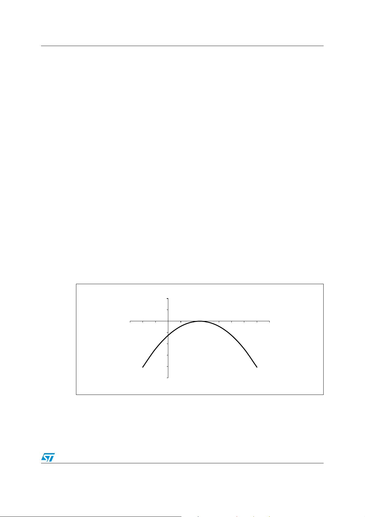
1.1 Crystal accuracy
The term “quartz-accurate” has become a familiar phrase used to describe the accuracy of
many time keeping functions. Quartz oscillators provide an accuracy far superior to that of
other conventional oscillator designs, but they are not perfect. Quartz crystals are sensitive
to temperature variations. Figure 1 shows the relationship between accuracy (acc),
temperature (T) and curvature (K) for a typical 32.768 kHz crystal. The curve follows the
general formula given below:
acc k T To–()
● To = 25 °C ± 5 °C
● K = –0.040 ppm/°C
×=
Note: The variable K is crystal-dependent, the value indicated here is for the crystal mounted on
the STM3210B-EVAL board. Refer to the crystal manufacturer for more details on this
parameter.
The clocks used in most applications require a high degree of accuracy, and there are
several factors involved in achieving this accuracy. Typically most crystals are compensated
for by adjusting the load capacitance of the oscillator. This method, though effective, has
several disadvantages:
1. it requires external components (trim capacitors)
2. it can increase the oscillator current (a major factor in battery-supported applications)
2
, where:
2
Instead of this crude analog method, STM32F10xxx products use a digital calibration
feature that gives the user software control over the calibrati on proced ur e , a nd make it userfriendly.
Figure 1. Typical crystal accuracy plotted against temperature
40
20
Temperature (˚C)
ai14625
–30 –20 –10
0
0
–20
–40
–60
–80
–100
10 20 30 40 50 60 70 80
Accuracy (ppm)
5/14
Page 6

RTC calibration basics AN2604 - Application note
1.2 Methodology
The RTC of STM32F10xxx products is driven by a quartz crystal-controlled oscillator with a
nominal frequency of 32.768 kHz. The crystal oscillator is one of the most accurate circuits
to provide a fixed frequency. There are two causes of clock error:
1. temperature variation
2. crystal variation
As mentioned previously, most clock chips compensate for crystal frequency and
temperature variations by using cumbersome trim capacitors. The STM32F10xxx design
employs periodic counter correcti ons. The digital calibration circuit r emoves 0 to 127 cycles
every 2
upon the value that has been loaded into the seven least significant bits of the BKP’s RTC
clock calibration register. Since the RTC clock calibration register is in the backup domain,
the calibration value is not lost even if the device is powered off provided that a battery is
connected to the V
Figure 2. RTC calibration clock output
20
clock cycles (see Figure 2.). The number of times the pulses are b lanked depends
pin.
BAT
CAL[6:0]bits in
BKP_RTCCR register
HSE/128
LSE
32 768 Hz
ANTI_TAMP
512 Hz output
for frequency test
1. The clock output on the ANTI_TAMP pin is the RTC clock before calibration, so its value is not changed by
the calibration.
Oscillator
Enabled by CCO bit in
BKP_RTCCR register
LSI
RTCCLK
Div64
Clock
calibration
RTC
ai14626
Each calibration step has the effect of subtracting 1 oscillator cycle every 1 048 576 (220)
actual oscillator cycles. That is, 0.954(1000000/2
20
) ppm of adjustment per calibration step
in the calibration register. As a result, the oscillator clock can be slowed down from 0 to
121 ppm.
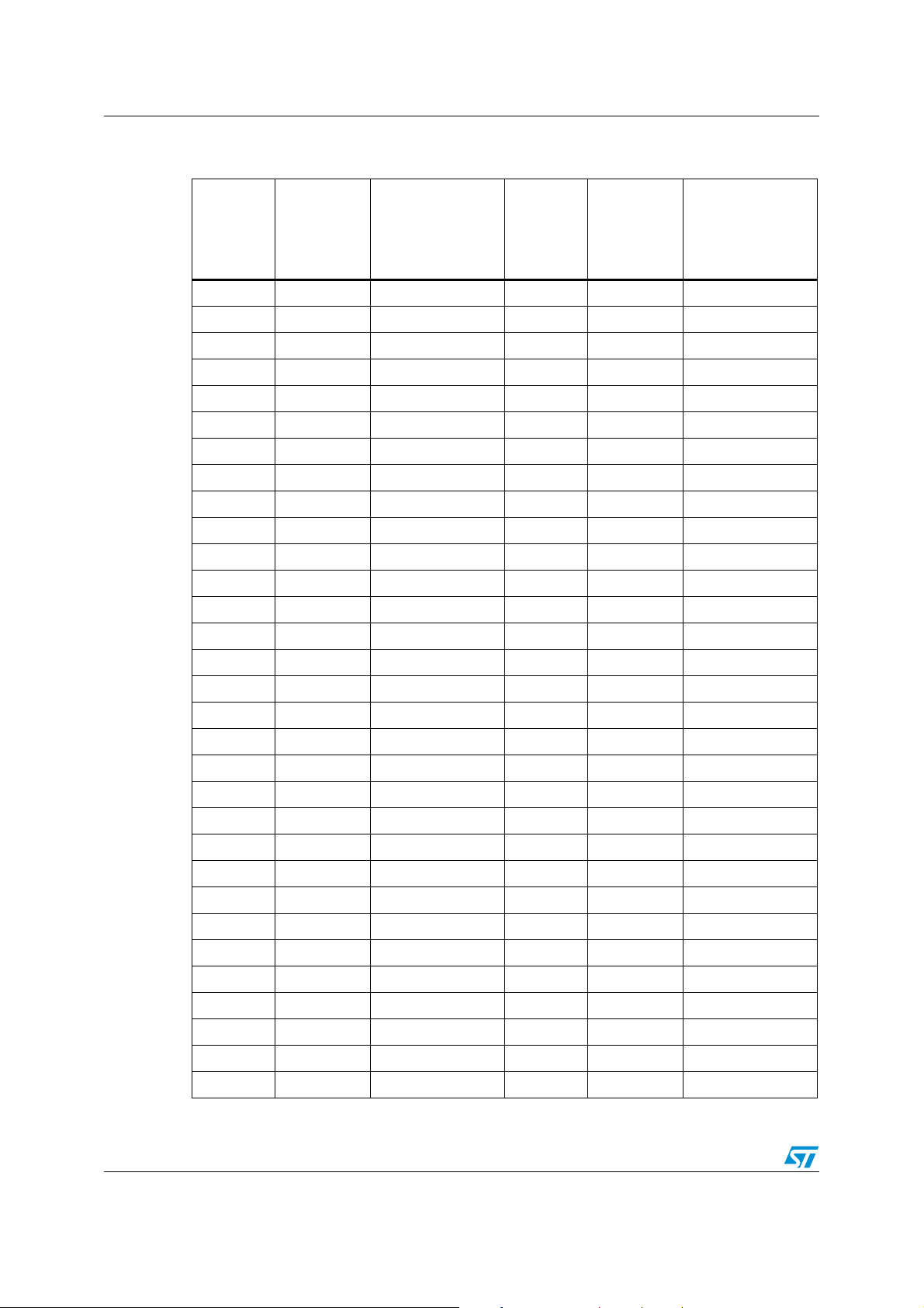
Table 1 on page 7 shows how many ppm and seconds per month (30 days) each bit
represents in real time.
6/14
Page 7

AN2604 - Application note RTC calibration basics
Table 1. Calibration table: compensation values in ppm and seconds per month
(30 days)
Calibration
value
Value in ppm
rounded to
the nearest
ppm
Value in seconds
per month (30
days) rounded to
the nearest
second
Calibration
value
Value in ppm
rounded to
the nearest
ppm
Value in seconds
per month (30
days) rounded to
the nearest
second
00 0 6461 158
11 2 6562 161
22 5 6663 163
33 7 6764 166
4 4 10 68 65 168
5 5 12 69 66 171
6 6 15 70 67 173
7 7 17 71 68 176
8 8 20 72 69 178
9 9 22 73 70 180
10 10 25 74 71 183
11 10 27 75 72 185
12 11 30 76 72 188
13 12 32 77 73 190
14 13 35 78 74 193
15 14 37 79 75 195
16 15 40 80 76 198
17 16 42 81 77 200
18 17 44 82 78 203
19 18 47 83 79 205
20 19 49 84 80 208
21 20 52 85 81 210
22 21 54 86 82 213
23 22 57 87 83 215
24 23 59 88 84 218
25 24 62 89 85 220
26 25 64 90 86 222
27 26 67 91 87 225
28 27 69 92 88 227
29 28 72 93 89 230
30 29 74 94 90 232
7/14
Page 8
RTC calibration basics AN2604 - Application note
Table 1. Calibration table: compensation values in ppm and seconds per month
(30 days) (continued)
Value in ppm
Calibration
value
31 30 77 95 91 235
32 31 79 96 92 237
33 31 82 97 93 240
34 32 84 98 93 242
35 33 87 99 94 245
36 34 89 100 95 247
37 35 91 101 96 250
38 36 94 102 97 252
39 37 96 103 98 255
40 38 99 104 99 257
41 39 101 105 100 260
42 40 104 106 101 262
43 41 106 107 102 264
44 42 109 108 103 267
rounded to
the nearest
ppm
Value in seconds
per month (30
days) rounded to
the nearest
second
Calibration
value
Value in ppm
rounded to
the nearest
ppm
Value in seconds
per month (30
days) rounded to
the nearest
second
45 43 111 109 104 269
46 44 114 110 105 272
47 45 116 111 106 274
48 46 119 112 107 277
49 47 121 113 108 279
50 48 124 114 109 282
51 49 126 115 110 284
52 50 129 116 111 287
53 51 131 117 112 289
54 51 133 118 113 292
55 52 136 119 113 294
56 53 138 120 114 297
57 54 141 121 115 299
58 55 143 122 116 302
59 56 146 123 117 304
60 57 148 124 118 307
61 58 151 125 119 309
8/14
Page 9

AN2604 - Application note RTC calibration basics
Table 1. Calibration table: compensation values in ppm and seconds per month
(30 days) (continued)
Value in ppm
Calibration
value
62 59 153 126 120 311
63 60 156 127 121 314
rounded to
the nearest
ppm
Value in seconds
per month (30
days) rounded to
the nearest
second
Calibration
value
Value in ppm
rounded to
the nearest
ppm
Value in seconds
per month (30
days) rounded to
the nearest
second
As described above, the STM32F10xxx RTC clock calibration circuit subtracts cycles only
from crystal clocks. And based on the fact that the RTC prescaler value is set by default to
32 768, faster crystal frequencies (> 32 768 Hz) can be calibrated whereas slower crystal
frequencies (< 32 768 Hz) cannot be compensated for. So only crystal frequencies in the
range [32 772, 32 768] can be calibrated.
Since the crystal frequency may vary about 32.768 kHz, a solution may be considered that
consists in setting the RTC presca ler to 32 766 ( instead of 32 768). The crystal frequency is
thus compared to 32 766 instead of 32 768. In this w ay, a crystal frequency in the range [32
770, 32 766] can be compensated.
Throughout the rest of the document, the considered RTC prescaler value will be 32 766.
9/14
Page 10

Calculating the needed amount of calibration AN2604 - Application note
2 Calculating the needed amount of calibration
To establish how much calibration is required in a given application, a method specially
suited to manufacturing en vironments is retained. It inv olv es the use of the R TC clock outp ut
mode, which derives a 512 Hz signal from t he cloc k divider ch ain as indica ted in Figure 2 on
page 6. This signal can be used to measure the accuracy of the crystal oscillator.
This method can be divided up into the following steps:
1. Enable the low speed external oscillator (LSE), select the LSE as the RTC clock
source, then enable the RTC clock.
2. Enable the RTC clock output with a fre quency divided by 64, on the ANTI_TAMP pin for
crystal frequency measurement. This is achieved by setting the CCO bit in
BKP_RTCCR.
3. Calculate the crysta l fre quen cy deviation in ppm. The deviation in ppm can be quickly
calculated by dividing the measured deviation from 511.968 Hz by 511.968 and, by
multiplying the result by 1 million. Find the nearest calibration value using Table 1 on
page 7. This table is a direct look- up table for calibration values based upon variation
values expressed in ppm.
4. Load the calibration value in the RTC calibration register to compensate for the crystal
deviation.
Note: To set the RTC prescaler to 32 766, write 32 765 into the RTC prescaler load register.
For example, if the frequency measured during the test mode is 511.982 Hz, the delta is
0.014. By dividing by 511.968 and multiplying by 1 million, the result is 27.35 ppm. In this
case, the nearest compensation value is 28. The inaccuracy will be reduced from 27.35 ppm
(~71 seconds per month) to 0.65 ppm (~1.7 second per month).
Note: Since RTC calibration is based on removing clock cycles, it does not improve counting over
short periods of time, it only improves counting over long periods. For example counting a
1/100 s using the RTC will be more accurate without calibration than with calibration. Since
calibration cycle removal may or not occur during the considered time frame, the resulting
value may change significantly. So depending on the application it may be better not to use
calibration.
10/14
Page 11

AN2604 - Application note Calculating calibration over a temper ature range
3 Calculating calibration over a temperature range
The calibration procedure described so far aims at calculating the correction for a specific
temperature. This section pro vides a procedur e for minimizing the frequency v ariation ov er a
wider temperature range. This involves adjusting the frequency curve so that there is an
equal amount of error above and below the zero (0) ppm point. Figure 3 on page 11 shows
how the frequency error can be minimized over a given temperature range.
The variables in the equation: (see Section 1.1 on page 5) are the
acc k T To–()
×=
following:
acc = Accuracy, in ppm, of the frequency, at the turnover temperature
K = Curvature characteristic = –0.04 ppm/°C
To = Turnover temperature in degrees Celsius = 25 °C ± 5 °C
T = Working temperature in degrees Celsius
For example, if a device shows a deviation of +27 ppm at room temperature, but the
operating temperature is 40 °C in the applicatio n, the equation ma y be used to calculate the
required calibration value as follows:
acc 27ppm 0.04ppm–()°C
acc 18ppm=
2
2
2
⁄()40° C25° C–()
×+=
2
Since the accuracy deviat ion is 18 ppm, the nearest calibrati on v alue as indicated in Table 1
on page 7, is 19.
Figure 3. Crystal accuracy over a temperature range
40
30
20
–30 –20 –10
10
0
0
10 20 30 40 50 60 70 80
–10
–20
–30
–40
–50
–60
–70
–80
–90
Accuracy (ppm)
After calibration
Temperature ˚C
Before calibration
ai14629
11/14
Page 12

Conclusion AN2604 - Application note
4 Conclusion
The STM32F10xxx RTC digital clock calibration feature allows the user to adjust the clock
accuracy during manufacturing (or later) at minimal cost. This feature also provides a
method whereby “drift” (due to temperature variation) can be corrected and/or anticipated.
However, the method described in this application note is applicable only if the RTC
prescaler is set to 32 766 (instead of 32 768).
12/14
Page 13

AN2604 - Application note Revision history
5 Revision history
Table 2. Document revision history
Date Revision Changes
31-Aug-2007 1 Initial release.
13/14
Page 14

AN2604 - Application note
Please Read Carefully:
Information in this document is provided solely in connection with ST products. STMicroelectronics NV and its subsidiaries (“ST”) reserve the
right to make changes, corrections, modifications or improvements, to this document, and the products and services described herein at any
time, without notice.
All ST products are sold pursuant to ST’s terms and conditions of sale.
Purchasers are solely res ponsibl e fo r the c hoic e, se lecti on an d use o f the S T prod ucts and s ervi ces d escr ibed he rein , and ST as sumes no
liability whatsoever relati ng to the choice, selection or use of the ST products and servi c es described herein.
No license, express or implied, by estoppel or otherwise, to any intellectual property rights is granted under this document. If any part of this
document refers to any third pa rty p ro duc ts or se rv ices it sh all n ot be deem ed a lice ns e gr ant by ST fo r t he use of su ch thi r d party products
or services, or any intellectua l property c ontained the rein or consi dered as a warr anty coverin g the use in any manner whats oever of suc h
third party products or servi ces or any intellectual property contained therein.
UNLESS OTHERWISE SET FORTH IN ST’S TERMS AND CONDITIONS OF SALE ST DISCLAIMS ANY EXPRESS OR IMPLIED
WARRANTY WITH RESPECT TO THE USE AND/OR SALE OF ST PRODUCTS INCLUDING WITHOUT LIMITATION IMPLIED
WARRANTIES OF MERCHANTABILITY, FITNESS FOR A PARTICUL AR PURPOS E (AND THEIR EQUIVALE NTS UNDER THE LAWS
OF ANY JURISDICTION), OR INFRINGEMENT OF ANY PATENT, COPYRIGHT OR OTHER INTELLECTUAL PROPERTY RIGHT.
UNLESS EXPRESSLY APPROVED IN WRITING BY AN AUTHORIZED ST REPRESENTATIVE, ST PRODUCTS ARE NOT
RECOMMENDED, AUTHORIZED OR WARRANTED FOR USE IN MILITARY, AIR CRAFT, SPACE, LIFE SAVING, OR LIFE SUSTAINING
APPLICATIONS, NOR IN PRODUCTS OR SYSTEMS WHERE FAILURE OR MALFUNCTION MAY RESULT IN PERSONAL INJ URY,
DEATH, OR SEVERE PROPERTY OR ENVIRONMENTAL DAMAGE. ST PRODUCTS WHICH ARE NOT SPECIFIED AS "AUTOMOTIVE
GRADE" MAY ONLY BE USED IN AUTOMOTIVE APPLICATIONS AT USER’S OWN RISK.
Resale of ST products with provisions different from the statements and/or technical features set forth in this document shall immediately void
any warranty granted by ST fo r the ST pro duct or serv ice describe d herein and shall not cr eate or exten d in any manne r whatsoever , any
liability of ST.
ST and the ST logo are trademarks or registered trademarks of ST in various countries.
Information in this document su persedes and replaces all information previously supplied.
The ST logo is a registered trademark of STMicroelectronics. All other names are the property of their respective owners.
© 2007 STMicroelectronics - All rights reserved
STMicroelectronics group of compan ie s
Australia - Belgium - Brazil - Canada - China - Czech Republic - Finland - France - Germany - Hong Kong - India - Israel - Italy - Japan -
Malaysia - Malta - Morocco - Singapore - Spain - Sweden - Switzerland - United Kingdom - United States of America
www.st.com
14/14
 Loading...