

Page 1

AN2593
Application note
STR91x interrupt management
Introduction
The objective of this application note is to explain the mechanism of the interrupt
management hardware in the STR91x microcontroller family, and also to provide application
developers with software recommendations for interrupt handling.
January 2009 Rev 2 1/15
www.st.com
Page 2

Contents AN2593
Contents
1 STR91x vectored interrupt controller VIC . . . . . . . . . . . . . . . . . . . . . . . . 3
1.1 VIC architecture overview . . . . . . . . . . . . . . . . . . . . . . . . . . . . . . . . . . . . . 3
1.2 VIC operation . . . . . . . . . . . . . . . . . . . . . . . . . . . . . . . . . . . . . . . . . . . . . . . 3
1.2.1 Interrupt configurations . . . . . . . . . . . . . . . . . . . . . . . . . . . . . . . . . . . . . . 4
1.2.2 FIQ interrupt management . . . . . . . . . . . . . . . . . . . . . . . . . . . . . . . . . . . . 5
1.2.3 IRQ interrupt management . . . . . . . . . . . . . . . . . . . . . . . . . . . . . . . . . . . 5
2 Software recommendations for handling interrupts . . . . . . . . . . . . . . . 7
2.1 Handling FIQ interrupts . . . . . . . . . . . . . . . . . . . . . . . . . . . . . . . . . . . . . . . 7
2.2 Handling IRQ interrupts . . . . . . . . . . . . . . . . . . . . . . . . . . . . . . . . . . . . . . . 8
2.3 Nested interrupt management . . . . . . . . . . . . . . . . . . . . . . . . . . . . . . . . . . 8
2.3.1 With interrupt nesting support . . . . . . . . . . . . . . . . . . . . . . . . . . . . . . . . . 8
2.3.2 Without interrupt nesting support . . . . . . . . . . . . . . . . . . . . . . . . . . . . . . . 9
3 Daisy-chained vectored interrupt service routine limitation . . . . . . . . 10
3.1 Description of the limitation . . . . . . . . . . . . . . . . . . . . . . . . . . . . . . . . . . . 10
3.2 Impact on user applications . . . . . . . . . . . . . . . . . . . . . . . . . . . . . . . . . . . 10
3.3 Daisy-chained interrupt flow sequence . . . . . . . . . . . . . . . . . . . . . . . . . . 10
3.4 Workaround using the STR9 firmware library . . . . . . . . . . . . . . . . . . . . . 11
4 Spurious VIC interrupts . . . . . . . . . . . . . . . . . . . . . . . . . . . . . . . . . . . . . 13
4.1 Definition . . . . . . . . . . . . . . . . . . . . . . . . . . . . . . . . . . . . . . . . . . . . . . . . . 13
4.2 Root causes and handling of spurious interrupts . . . . . . . . . . . . . . . . . . . 13
5 Revision history . . . . . . . . . . . . . . . . . . . . . . . . . . . . . . . . . . . . . . . . . . . 14
2/15
Page 3
AN2593 STR91x vectored interrupt controller VIC
VIC0.15
VIC0.0
VIC1.15
VIC1.0
VIC0
VIC1
ARM966
IRQ
FIQ
Daisy
chain
core
Vectored Interrupt 0
Interrupt source 0
Interrupt source 1
Interrupt source 15
Interrupt
Request
Logic
FIQ to CPU
IRQ Priority
IRQ to CPU
Vector Address Register
FIQ Logic
Vectored Interrupt 0 ISR Address
Vectored Interrupt 15
Vectored Interrupt 15 ISR Address
IRQ
FIQ
Logic
FIQ status Register
IRQ status register
1 STR91x vectored interrupt controller VIC
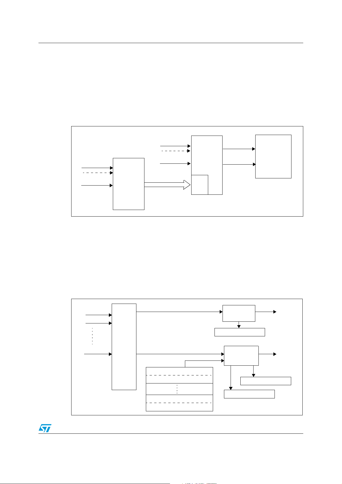
1.1 VIC architecture overview
In the STR91x microcontroller, the Vectored Interrupt Controller VIC is implemented by
daisy-chaining two standard ARM primecells (PL190) VICs.
Figure 1 gives an overview of the hardware connections:
Figure 1. STR91x VIC architecture
As shown in Figure 1, sixteen interrupt lines are connected to each VIC (see datasheet for
information about each interrupt source).
The choice of connecting two VICs in a daisy-chain was made in order to allow vectored
interrupt support for all 32 interrupt lines of the STR91x.
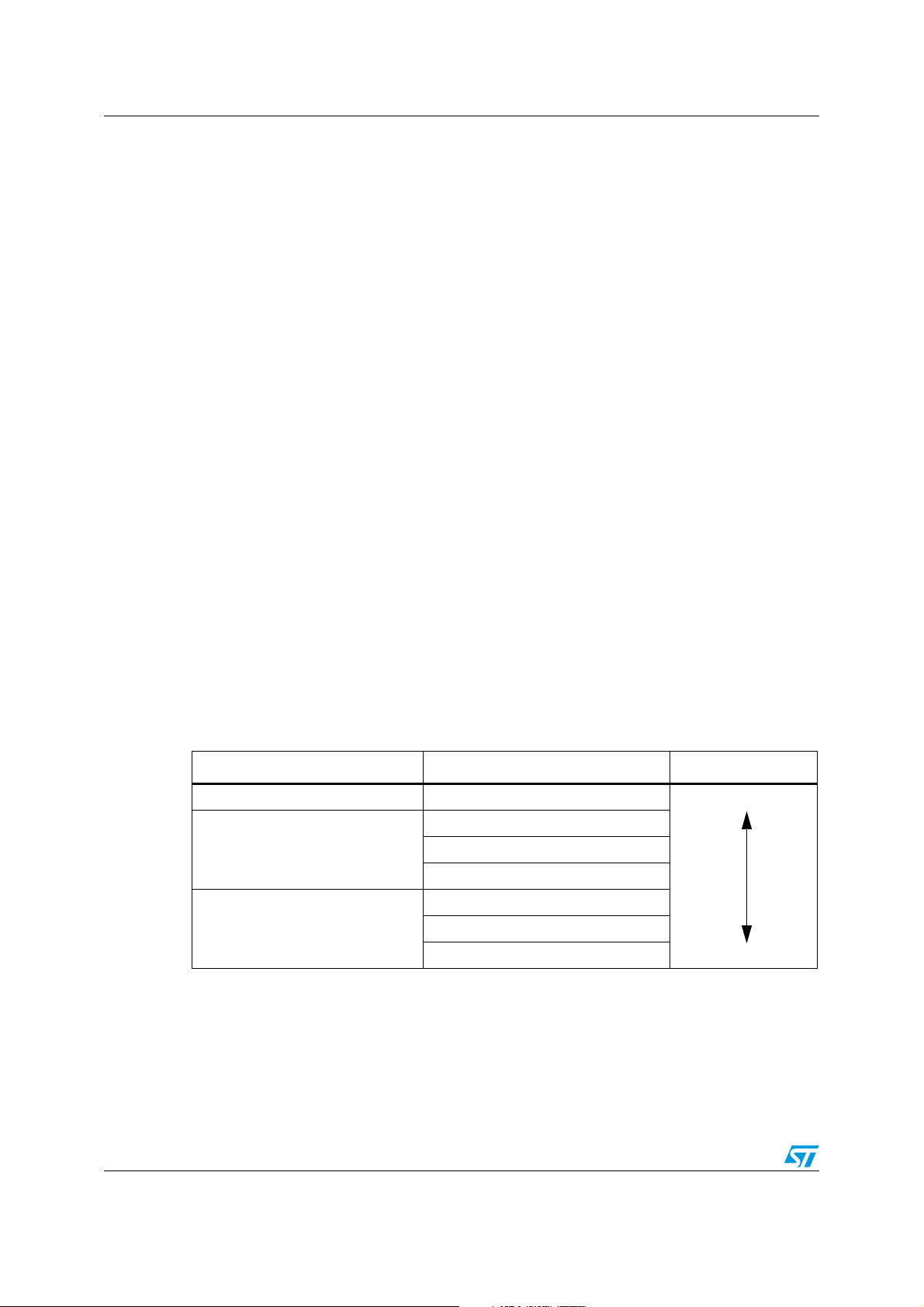
1.2 VIC operation
Figure 2 provides a schematic view of the VIC (single VIC) block diagram:
Figure 2. Overview of the VIC block diagram
3/15
Page 4
STR91x vectored interrupt controller VIC AN2593
Highest
Lowest
1.2.1 Interrupt configurations
Any interrupt source can be configured as IRQ or as FIQ (Fast Interrupt Request).
IRQ interrupt configuration
In each VIC, an IRQ interrupt can have a priority ranging from 0 to 15 (priority 0 is the
highest priority and 15 is the lowest).
In order to assign a priority level to an IRQ interrupt, using the following procedure:
1. Assign one of the vectored interrupts (from 0 to 15) to the interrupt source by
configuring the selected VIC Vector Control i register VICx_VCiR.
2. Program the address of the interrupt service routine (ISR) in the selected vectored
interrupt Vector Address i register VIC_VAiR.
3. Enable the IRQ interrupt by setting the corresponding bit in the VIC Interrupt Enable
register VICx_INTER
4. Enable the selected vectored interrupt in the VICx_VCiR register.
Caution: Due to the VIC daisy-chained implementation, IRQ interrupts from VIC0 have always higher
priority than VIC1 interrupts (hardwired priority), this means for example that an interrupt
from VIC1 configured with a priority level 0 has a lower priority than a VIC0 interrupt
configured with a priority level 15.
FIQ interrupt configuration
In order to configure a VIC interrupt source as FIQ, you have to set the corresponding bit in
the VIC Interrupt Select register VICx_INTSR, and then enable the interrupt by setting the
corresponding bit in the VIC Interrupt Enable register VICx_INTER.
Note: FIQ interrupts have the highest interrupt priority level. Unlike IRQ interrupts, FIQ interrupts
have no vectored interrupt support or priority management.
Ta bl e 1 summarizes the interrupt priority levels in the VICs:
Table 1. Summary of the interrupt priorities in the VICs
Interrupt Configured priority level in the VICs Priority
VIC0/VIC1 FIQ NA
0
VIC0 IRQ
VIC1 IRQ
...
15
0
...
15
4/15
Page 5

AN2593 STR91x vectored interrupt controller VIC
1.2.2 FIQ interrupt management
For FIQ there are no priority levels. When an enabled FIQ interrupt occurs, the VIC signals it
directly to the ARM core by asserting the FIQ interrupt line.
Then the ARM core switches to FIQ mode, and goes to address 0x1C where you must
implement the FIQ interrupt handler.
Normally in order to lower FIQ interrupt latency only one interrupt should be configured as
FIQ. But it is possible to configure several interrupts as FIQ, and in this case the application
software must read the FIQ status registers of both VIC0 and VIC1 in order to determine the
source of the FIQ interrupt.
When the interrupt flag is cleared in the peripheral(s) that generated the interrupt, the VIC
then will stop asserting the FIQ interrupt to CPU and the flag will be cleared in the VIC FIQ
status register.
1.2.3 IRQ interrupt management
There are two possible ways for handling IRQ interrupts in the VIC:
1. Vectored handling
2. Simple (Non vectored) handling
Vectored handling ensures the best interrupt latency because it takes advantage of the
vectored support in the VIC.
Simple handling does not use the hardware priority management of the VIC, but it uses a
software priority management. Although this method increases the interrupt latency, it can
be useful in special cases where a VIC1 interrupt has to be configured with a higher priority
level than a VIC0 interrupt, this is not possible when using the hardware priority
management due to the hardwired priority between VIC0 and VIC1 (see Section 1.2.1).
Vectored handling of IRQ interrupts
When an IRQ interrupt from VIC0 or from VIC1 occurs, then depending on its priority level,
two cases are possible:
– If the interrupt has a lower priority than the current interrupt being processed, then it
remains pending in the VIC until it becomes the higher priority interrupt.
– If the interrupt has the highest priority level then the VIC0 Vector Address register
VIC0_VAR will be loaded with the address of the interrupt service routine and an IRQ
interrupt will be signalled to CPU.
Note: The VIC0_VAR will be loaded with the ISR address of the interrupt independently from the
origin of the interrupt either from VIC0 or from VIC1.
The vectored flow for handling an IRQ interrupt is the following:
5/15
Page 6

STR91x vectored interrupt controller VIC AN2593
1. In the IRQ interrupt handler, the software should read the VIC0 vector address register
VIC0_VAR in order to determine the address of the interrupt service routine and jump
to it.
2. If the interrupt originates from VIC0, then reading the VIC0 vector address register in
step 1 will update the priority logic of VIC0: so interrupts with the same or lower priority
levels will be masked by the VIC.
But if an interrupt originates from VIC1 then you must also perform a read from the
VIC1 vector address registerVIC1_VAR in order to update the priority logic in VIC1.
3. After finishing the interrupt processing including the clearing of the interrupt flags, you
must write any value in the VIC0 vector address register if the interrupt originates from
VIC0, or in the VIC1 vector address register if the interrupt is from VIC1, this in order to
indicate to the VIC that interrupt processing has finished, so it can update the priority
logic: then a same or lower level interrupt will be able to interrupt the CPU.
Simple (non vectored) handling of IRQ interrupts
This method of handling IRQ interrupts does not use the VIC hardware priority
management, so this means you do not have to read or write the VIC0_VAR or VIC1_VAR
registers to update the hardware priority logic.
This method can be used when there is a need to give higher priority to a VIC1 interrupt
over a VIC0 interrupt.
The flow for simple (non vectored) IRQ handling is the following:
1. An IRQ interrupt occurs.
2. Branch to the interrupt handler.
3. Read the VICs IRQ Status registers to determine the source that generated the
interrupt, and prioritize the interrupts if there are multiple active interrupt sources.
4. Branch to the corresponding interrupt service routine.
5. Execute the interrupt service routine.
6. Clear the interrupt. If a software interrupt generated the request, you must write to the
VICx_SWINTCR register.
7. Check the IRQ Status registers of both VICs to ensure that no other interrupt is active.
If there is an active request, go to Step 4.
8. Return from the interrupt.
6/15
Page 7

AN2593 Software recommendations for handling interrupts
2 Software recommendations for handling interrupts
2.1 Handling FIQ interrupts
When a FIQ interrupt occurs the CPU will jump to address 0x1C.
You must implement the FIQ service routine at address 0x1C.
A FIQ handler should be coded as follows:
@0x1C FIQHandler:
; save context
; read FIQ Status Register(VICx_FSR) to determine FIQ src
; service FIQ interrupt
; restore context
Normally only one interrupt source is configured as FIQ, so when this interrupt occurs, you
process it directly without needing to read the VICx_FSR register to determine the interrupt
source.
7/15
Page 8

Software recommendations for handling interrupts AN2593
2.2 Handling IRQ interrupts
Note: In this section, only vectored handling of interrupts is explained.
When an IRQ interrupt occurs CPU will jump to address 0x18.
Then user has two options for managing the IRQs, the first option is:
● Jumping directly to the Interrupt service routine by doing a relative jump to the value
indicated in the VIC0 Vector Address register (mapped at 0xFFFFFF030):
@0x18 LDR PC, [PC, #-0xFF0]
If choosing this option, then you need to define your ISR as “irq” by adding the “__irq “
attribute when defining the interrupt service routine function, example:
__irq void TIM0_IRQHandler (void) //example with IAR EWARM
The attribute __irq which is compiler dependent is added in order to instruct the
preprocessor to add necessary code for saving the registers in the stack at the beginning of
the interrupt service routine and restoring the registers at the end of interrupt processing.
The second option for servicing interrupt is:
● Jumping to an IRQHandler as a first step in which you perform a context save, then
jumping to the ISR after reading the VIC0 vector address register (VIC0_VAR).
@0x18 LDR PC, IRQHandler
...
IRQHandler:
; Save context
; Read ISR address from VIC0 vector Address Register
; Branch with Link to ISR
; Restore context
For both options, in the ISR code you will need to manage the VIC priority:
– If the interrupt comes from VIC0 then you will need to write any value to VIC0_VAR
register at the end of the interrupt processing in order to update the VIC priority.
There is no need to do a read of VIC0_VAR, this was done when jumping to the ISR.
– If the interrupt comes from VIC1 AND if nested interrupt management (and thus also
priority management) is needed then in this case you will need to do a read of
VIC1_VAR at the beginning of the ISR and a write to VIC1_VAR at the end of the ISR
processing in order to update the VIC1 priority logic.
2.3 Nested interrupt management
2.3.1 With interrupt nesting support
When supporting nested interrupts, an interrupt service routine can be interrupted by a
higher priority interrupt.
It is important to know that the ARM core will disable IRQs when an IRQ interrupt occurs. So
in order to be able to support interrupt nesting you must re-enable interrupts in the interrupt
service routine, then disable them when exiting the ISR.
Two inline assembly code macros should be used: IENABLE and IDISABLE.
8/15
Page 9

AN2593 Software recommendations for handling interrupts
The IENABLE macro ensures the reenabling of interrupts in system mode in order to allow
interrupt nesting. IDISABLE disables IRQs when exiting from the interrupt service routine
and returning to IRQ mode.
#define IENABLE asm(" MRS LR, SPSR"); /* Copy SPSR_irq to LR */ \
asm("STMFD SP!, {LR} "); /* Save SPSR_irq */ \
asm("MSR CPSR_c, #0x1F "); /* Switch to SYS mode with IRQ enabled*/ \
asm("STMFD SP!, {LR} ") ; /* Save SYS mode LR */
#define IDISABLE asm("LDMFD SP!, {LR}") ; /* Restore SYS mode LR */ \
asm("MSR CPSR_c, #0x92") ; /* Switch to IRQ mode with IRQ disabled*/ \
asm("LDMFD SP!, {R0}") ; /* Restore SPSR_irq to R0 */ \
asm("MSR SPSR_cxsf, R0") ; /* Copy R0 to SPSR_irq */
Example : Timer0 interrupt (interrupt on VIC0)
void TIM0_IRQHandler (void)
{
/* switch to system mode with IRQ enabled*/
IENABLE;
/* clear interrupt flag and process interrupt */
...
...
...
/* switch to IRQ mode with IRQ disabled*/
IDISABLE;
/* write any value to VIC0 Vector address register */
VIC0->VAR = 0xFF
}
2.3.2 Without interrupt nesting support
If your application does not need nested interrupt support then you should not insert the
IENABLE and IDISABLE macros.
But you still need to write any value to VIC0 Vector Address register at end of interrupt
processing, if the interrupt originates from VIC0, this is in order to update the VIC0 priority
logic after reading the VIC0 Vector Address in order to jump to the interrupt service routine.
Because there is no priority managment to be done, you are not obliged to do a read of
VIC1 Vector address register at the start of a VIC1 interrupt service routine nor to do a write
to this register at the end of interrupt processing.
9/15
Page 10

Daisy-chained vectored interrupt service routine limitation AN2593
3 Daisy-chained vectored interrupt service routine
limitation
3.1 Description of the limitation
For daisy-chained interrupts, if the VAR of only one VIC is read, it does not update the
hardware priority in the other VIC. This means the daisy chained interrupt controller doesn't
realize the interrupt is being serviced and keeps the interrupt request active.
For daisy-chained interrupts, the processor must read the VAR register of both interrupt
controllers and branch to the addresses provided. However the address provided by reading
the daisy-chained VAR register must be manipulated to skip the interrupt preamble. If two
daisy chained interrupts occur soon after each other and the daisy chained VAR register
address isn't branched to, the interrupt controller priority logic may be updated incorrectly.
This may cause a low priority interrupt to be missed.
The ARM Prime cell support team has planned to add a new section 2.2.3 in the TRM
(ARM-DDI-0181E) titled 'Daisy-chained interrupt flow sequence' to provide information
about the handling of daisy-chained interrupts. Consequently ST is not planning to change
the interrupt handling scheme in the STR9 firmware library, instead, as recommended by
ARM, we propose a workaround for handling all daisy-chained interrupts properly (see
Section 3.4).
3.2 Impact on user applications
The above limitation can be considered a having a low severity level since problems may
occur only in a few specific timing conditions when handling nested interrupts on VIC1.
Hence, customers who do not use nested interrupts on VIC1, do not have to change their
software. They can safely continue with the interrupt handling as it is implemented in the
STR9 firmware library.
For those who are using nesting on VIC1 in their applications, they should apply the
sequence for servicing daisy-chained interrupts recommended by ARM and given here in
Section 3.3.
3.3 Daisy-chained interrupt flow sequence
As it was stated in a previous section, there are two daisy-chained VICs in the STR91x
device. VIC0 is directly connected to the CPU and VIC1 is connected to VIC0.
The daisy-chaining works as follows:
1. An interrupt occurs.
2. The ARM processor branches to either the IRQ or FIQ interrupt vector.
3. If the interrupt is an IRQ, read the VICVectAddr Register in VIC0 and branch to the
interrupt service routine. You can do this using an LDR PC instruction. Reading the
VICVectorAddr register updates the interrupt controller’s hardware priority register.
4. Stack the workspace
5. If the interrupt is coming from a VIC1 source, read the VICVectAddr register in the
daisy chained interrupt controller VIC1. Reading the VICVectorAddr Register updates
10/15
Page 11

AN2593 Daisy-chained vectored interrupt service routine limitation
the interrupt controller’s hardware priority register in the daisy chained interrupt
controller. Branch to the interrupt service routine address given by VICVectorAddr for
VIC1 plus offset to skip the interrupt stacking preamble. You can do this using an LDR
PC instruction.
6. Execute the "IENABLE" macro so that a higher priority can be serviced.
7. Execute the Interrupt Service Routine (ISR).
8. Clear the requesting interrupt in the peripheral, or write to the VICSoftIntClear Register
if the request was generated by a software interrupt.
9. Execute the "IDISABLE" macro to disable IRQs when exiting from the interrupt service
routine and returning to IRQ mode.
10. Write to the daisy chained VICVectAddr Register VIC1. This clears the respective
interrupt in the daisy chained interrupt controller.
11. Return from the interrupt. This re-enables interrupts.
Note: The description of the limitation and the flow sequence handling are taken mainly from the
ARM Prime Cell Vectored Interrupt Controller (PL190) Errata Notice.
3.4 Workaround using the STR9 firmware library
For already existing software that services daisy-chained nested interrupts, a possible
software workaround would be to branch to the address provided by the VIC1 VAR register.
This ensures that the correct ISR is serviced. (Refer to Tabl e 2).
To do this an inline assembly code macro could be used:
#define DAISY_VIC asm("MOV r11, #0xFC000000"); /* VectorAddressDaisy address */ \
asm("ADD r11, r11, #0x30"); /* VectorAddressDaisy address */ \
asm("LDR r11, [r11]"); /* Update VIC1 hardware priority */ \
asm("ADD r11 ,r11 , #0x18"); /* Skip the preamble (+0x18) */ \
asm("BX r11"); /* Branch to the highest priority*/ \
/*interrupt from VIC1 */
Please note that the value 0x18 used in instruction "ADD r11, r11, #0x18" is only specific to
the example code given here. The offset #0x18 will be dependent on the system's interrupt
stacking preamble code size.
Example: EXTI0 interrupt (interrupt on VIC1)
void EXTIT0_IRQHandler (void)
{
/*VIC1 Hardware Priority update and branch to the highest priority interrupt*/
DAISY_VIC;
/* switch to system mode with IRQ enabled*/
IENABLE;
/* clear interrupt flag and process interrupt */
...
...
/* switch to IRQ mode with IRQ disabled
IDISABLE;
/* Write any value to VIC1 Vector address register */
VIC1->VAR = 0xFF}
11/15
Page 12

Daisy-chained vectored interrupt service routine limitation AN2593
IRQ1
IRQ2
IRQ1
IRQ2
IRQ1
IRQ2
IRQ1
IRQ2
Table 2. Nesting of two interrupts on VIC1, with and without "DAISY_VIC" Macro
With DAISY_VIC Macro Without DAISY_VIC Macro
Priority: IRQ1 < IRQ2
Priority: IRQ1 > IRQ2
Note: A software project is provided with this application note, showing an example of three
nested interrupts with a TIMER output compare interrupt through VIC0 and two EXTIT
interrupts through VIC1.
12/15
Page 13

AN2593 Spurious VIC interrupts
4 Spurious VIC interrupts
4.1 Definition
Spurious interrupts are a characteristic of the VIC. This is due to the pipelined architecture
of the ARM core.
We know that when an interrupt occurs and it has the highest priority level, the VIC signals
an IRQ interrupt to the CPU and the VIC0 vector address register is loaded with the ISR
address.
Now suppose that just after having asserted the IRQ signal to the CPU, due to certain root
causes which are explained in the next section (Section 4.2), the interrupt source to VIC is
cleared, then in this case the VIC0 vector address register won’t be loaded with the ISR
address because the interrupt source was cleared in VIC. Instead, a default value is loaded
from the Defaut Vector Address register VIC0_DVAR.
So consequently the CPU will then jump to the default vector instead of the interrupt ISR
address: this is what we call “Spurious Interrupt”.
4.2 Root causes and handling of spurious interrupts
The reason why an interrupt in VIC could get cleared before being serviced is the fact that
CPU continues to executes some code in the pipeline before servicing the interrupt, and this
code in the pipeline could either:
1. Clear the interrupt flag in the peripheral, so the interrupt is no longer asserted to the
VIC
2. The code in the ARM pipeline disables the interrupt in the VIC
Note: The reset value of the VIC0 Default Vector Address register is 0x0 so when a spurious
interrupt occurs the CPU will jump to address 0x0, which gives a surprising RESET-like
behavior.
In some applications, you can not avoid the possiblility of spurious interrupts occurring.
An example of this, is when you are working on peripherals with FIFO support like UART, in
these peripherals, the FIFO receive/transmit interrupt flags may be cleared simply by a
read/write in the FIFO, so it could be possible that an interrupt has been signalled to the VIC
but you have executed some code in pipeline which accessed the FIFO.
In order to avoid the surprising reset-like behaviour, it is important to assign a dummy
handler to the Default vector address registers of VIC0 and VIC1.
VIC0->DVAR = (u32)Dummy_Handler;
VIC1->DVAR = (u32)Dummy_Handler;
In this dummy handler just write any value to VIC0 and VIC1 vector address registers.
void Dummy_Handler(void)
{
VIC0->VAR = 0xFF;
VIC1->VAR = 0XFF;
}
13/15
Page 14

Revision history AN2593
5 Revision history
Table 3. Document revision history
Date Revision Changes
31-Jan-2008 1 Initial release
26-Jan-2009 2
Added Section 3: Daisy-chained vectored interrupt service
routine limitation on page 10
14/15
Page 15

AN2593
Please Read Carefully:
Information in this document is provided solely in connection with ST products. STMicroelectronics NV and its subsidiaries (“ST”) reserve the
right to make changes, corrections, modifications or improvements, to this document, and the products and services described herein at any
time, without notice.
All ST products are sold pursuant to ST’s terms and conditions of sale.
Purchasers are solely responsible for the choice, selection and use of the ST products and services described herein, and ST assumes no
liability whatsoever relating to the choice, selection or use of the ST products and services described herein.
No license, express or implied, by estoppel or otherwise, to any intellectual property rights is granted under this document. If any part of this
document refers to any third party products or services it shall not be deemed a license grant by ST for the use of such third party products
or services, or any intellectual property contained therein or considered as a warranty covering the use in any manner whatsoever of such
third party products or services or any intellectual property contained therein.
UNLESS OTHERWISE SET FORTH IN ST’S TERMS AND CONDITIONS OF SALE ST DISCLAIMS ANY EXPRESS OR IMPLIED
WARRANTY WITH RESPECT TO THE USE AND/OR SALE OF ST PRODUCTS INCLUDING WITHOUT LIMITATION IMPLIED
WARRANTIES OF MERCHANTABILITY, FITNESS FOR A PARTICULAR PURPOSE (AND THEIR EQUIVALENTS UNDER THE LAWS
OF ANY JURISDICTION), OR INFRINGEMENT OF ANY PATENT, COPYRIGHT OR OTHER INTELLECTUAL PROPERTY RIGHT.
UNLESS EXPRESSLY APPROVED IN WRITING BY AN AUTHORIZED ST REPRESENTATIVE, ST PRODUCTS ARE NOT
RECOMMENDED, AUTHORIZED OR WARRANTED FOR USE IN MILITARY, AIR CRAFT, SPACE, LIFE SAVING, OR LIFE SUSTAINING
APPLICATIONS, NOR IN PRODUCTS OR SYSTEMS WHERE FAILURE OR MALFUNCTION MAY RESULT IN PERSONAL INJURY,
DEATH, OR SEVERE PROPERTY OR ENVIRONMENTAL DAMAGE. ST PRODUCTS WHICH ARE NOT SPECIFIED AS "AUTOMOTIVE
GRADE" MAY ONLY BE USED IN AUTOMOTIVE APPLICATIONS AT USER’S OWN RISK.
Resale of ST products with provisions different from the statements and/or technical features set forth in this document shall immediately void
any warranty granted by ST for the ST product or service described herein and shall not create or extend in any manner whatsoever, any
liability of ST.
ST and the ST logo are trademarks or registered trademarks of ST in various countries.
Information in this document supersedes and replaces all information previously supplied.
The ST logo is a registered trademark of STMicroelectronics. All other names are the property of their respective owners.
© 2009 STMicroelectronics - All rights reserved
STMicroelectronics group of companies
Australia - Belgium - Brazil - Canada - China - Czech Republic - Finland - France - Germany - Hong Kong - India - Israel - Italy - Japan -
Malaysia - Malta - Morocco - Singapore - Spain - Sweden - Switzerland - United Kingdom - United States of America
www.st.com
15/15
 Loading...