

Page 1

AN2579
Application note
LIS302DL 3-axis digital MEMS accelerometer
translates finger taps into actions
Introduction
This document is intended to provide application information for the LIS302DL low-voltage
3-axis digital output linear MEMS accelerometer housed in an LGA package.
The LIS302DL is an ultra-compact low-power 3-axis linear accelerometer that includes a
sensing element and an IC interface capable taking information from the sensing element
and providing the measured acceleration data to external applications via an I2C/SPI serial
interface.
The sensing element used to detect acceleration is manufactured using a dedicated process
developed by ST to produce inertial sensors and actuators in silicon.
The IC interface is instead manufactured using a CMOS process that allows a high level of
integration to design a dedicated circuit which is factory trimmed to better match the sensing
element characteristics.
The LIS302DL has a user-selectable full scale of ±2g and ±8g and is capable of measuring
accelerations with an output data rate of 100 Hz or 400 Hz. A self-test capability allows the
user to check that the system is operating correctly.
The device features two independent, highly programmable interrupt sources that can be
configured either to generate an inertial wake-up interrupt signal when a programmable
acceleration threshold is exceeded along one of the three axes, to detect a free-fall or to
recognize single/double click events.
Two independent pins can be configured to provide interrupt signals to connected devices.
The LIS302DL is available in a plastic SMD package and is designed to operate over a
temperature range extending from -40 °C to +85 °C.
The ultra small size and weight of the SMD package make it an ideal choice for handheld
portable applications such as cell phones and PDAs, or any other application where
reduced package size and weight are required.
January 2008 Rev 1 1/15
www.st.com
Page 2

Contents AN2579
Contents
1 Theory of operation . . . . . . . . . . . . . . . . . . . . . . . . . . . . . . . . . . . . . . . . . 3
1.1 Single click . . . . . . . . . . . . . . . . . . . . . . . . . . . . . . . . . . . . . . . . . . . . . . . . . 3
1.2 Double click . . . . . . . . . . . . . . . . . . . . . . . . . . . . . . . . . . . . . . . . . . . . . . . . 4
2 Register description . . . . . . . . . . . . . . . . . . . . . . . . . . . . . . . . . . . . . . . . . 6
2.1 CLICK_CFG (38h) . . . . . . . . . . . . . . . . . . . . . . . . . . . . . . . . . . . . . . . . . . . 6
2.2 CLICK_SRC (39h) . . . . . . . . . . . . . . . . . . . . . . . . . . . . . . . . . . . . . . . . . . . 6
2.3 CLICK_THSY_X (3Bh) . . . . . . . . . . . . . . . . . . . . . . . . . . . . . . . . . . . . . . . . 7
2.4 CLICK_THSZ (3Ch) . . . . . . . . . . . . . . . . . . . . . . . . . . . . . . . . . . . . . . . . . . 7
2.5 CLICK_TimeLimit (3Dh) . . . . . . . . . . . . . . . . . . . . . . . . . . . . . . . . . . . . . . . 8
2.6 CLICK_Latency (3Eh) . . . . . . . . . . . . . . . . . . . . . . . . . . . . . . . . . . . . . . . . 8
2.7 CLICK_Window (3Fh) . . . . . . . . . . . . . . . . . . . . . . . . . . . . . . . . . . . . . . . . 8
2.8 CTRL_REG3 [Interrupt CTRL register] (22h) . . . . . . . . . . . . . . . . . . . . . . . 8
3 Examples . . . . . . . . . . . . . . . . . . . . . . . . . . . . . . . . . . . . . . . . . . . . . . . . . 10
3.1 Playing with CLICK_TimeLimit . . . . . . . . . . . . . . . . . . . . . . . . . . . . . . . . . 10
3.2 Playing with CLICK_Latency . . . . . . . . . . . . . . . . . . . . . . . . . . . . . . . . . . 12
3.3 Playing with CLICK_Window . . . . . . . . . . . . . . . . . . . . . . . . . . . . . . . . . . 13
4 Revision history . . . . . . . . . . . . . . . . . . . . . . . . . . . . . . . . . . . . . . . . . . . 14
2/15
Page 3
AN2579 Theory of operation
1 Theory of operation
The single click and double click recognition functions featured in the LIS302DL help to
create a man-machine interface with little software loading. The device can be configured to
output an interrupt signal on a dedicated pin when tapped in any direction.
If the sensor is exposed to a single input stimulus, it generates an interrupt request on
inertial interrupt pin INT1 and/or INT2. A more advanced feature allows the generation of an
interrupt request when a double input stimulus with programmable time between the two
events is recognized, enabling a mouse button-like functionality.
This function can be fully programmed by the user in terms of expected amplitude and
timing of the stimuli by means of the dedicated set of registers described in Chapter 2:
Register description.
The single and double click recognition works independently on the selected output data
rate.
1.1 Single click
If the device is configured for single click event detection, an interrupt is generated when the
input acceleration on the selected channel exceeds the programmed threshold, and returns
below it within a time window defined by the TimeLimit register.
If the LIR bit of the CLICK_CFG register is not set, the interrupt is kept high for the duration
of the Latency window. If the LIR bit is set, the interrupt is kept high until the CLICK_SRC
register is read.
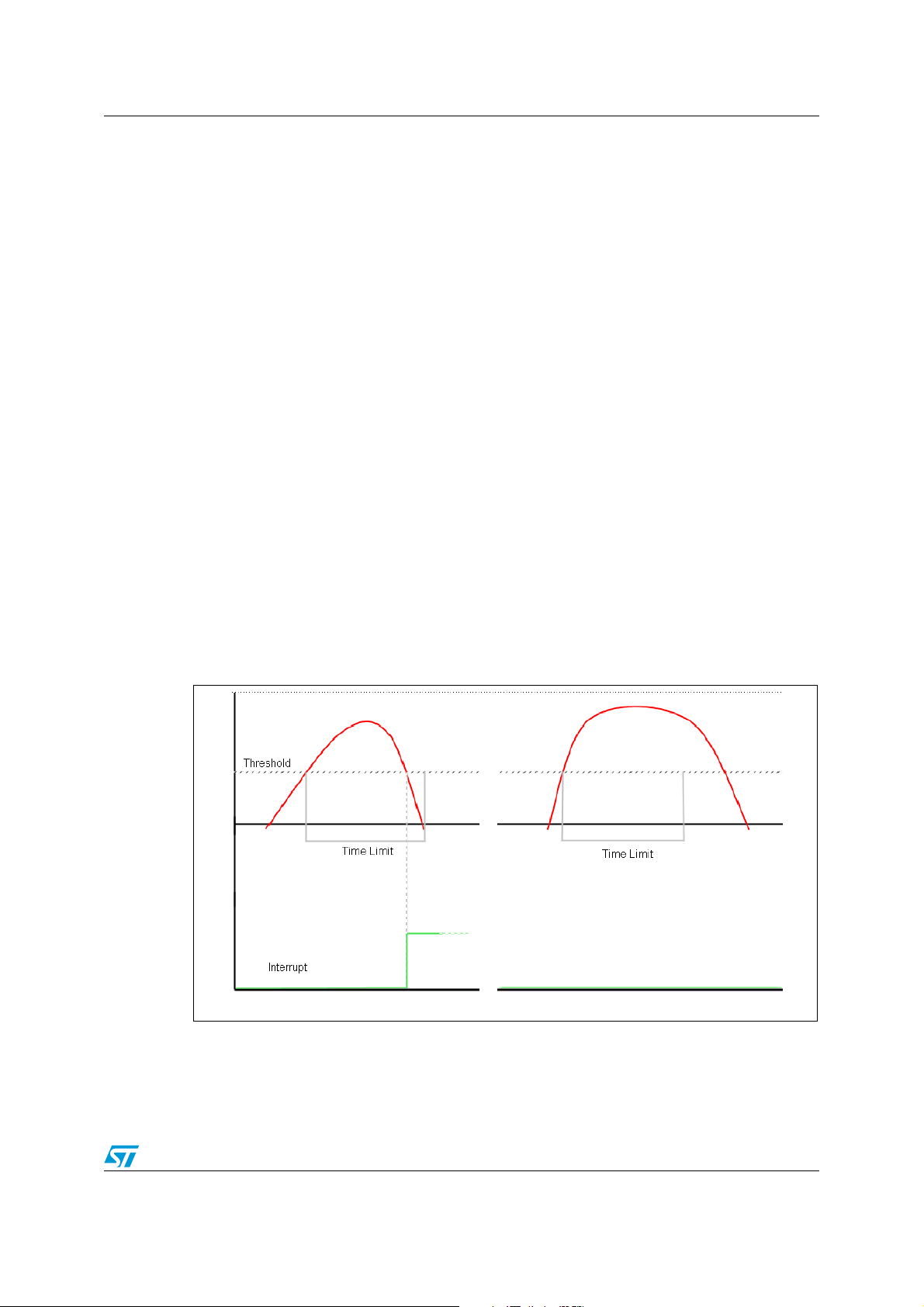
Figure 1. Single click event with non latched interrupt
(a) (b)
In Figure 1(a) the click has been recognized, while in Figure 1(b) the click has not been
recognized because the acceleration goes under the threshold after the TimeLimit has
expired.
3/15
Page 4
Theory of operation AN2579
1.2 Double click
If the device is configured for double click event detection, an interrupt is generated when,
after a first click, a second click is recognized. The recognition of the second click occurs
only if the event satisfies the rules defined by the Latency and Windows registers.
In particular, after the first click has been recognized, the second click detection procedure
is delayed for an interval defined by the Latency register. This means that after the first click
has been recognized, the second click detection procedure will start only if the input
acceleration exceeds the threshold after the Latency window but before the Window has
expired [Figure 2(a)] or if the acceleration is still above the threshold after the Latency has
expired [Figure 3(b)].
Once the second click detection procedure is initiated, the second click will be recognized
with the same rule as the first: the acceleration must return below the threshold before the
TimeLimit has expired.
Appropriately defining the Latency window is important to avoid unwanted clicks due to
spurious bouncing of the input signal.
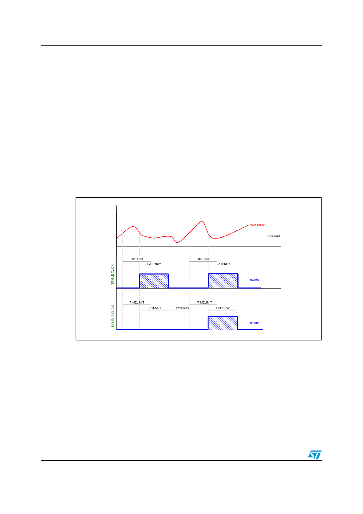
Figure 2. Single and double click recognition
(a)
(b)
Figure 2 illustrates a single click event (a) and a double click event (b). The device is able to
distinguish between (a) and (b) by changing the settings of the CLICK_CFG register from
single to double click recognition.
4/15
Page 5
AN2579 Theory of operation
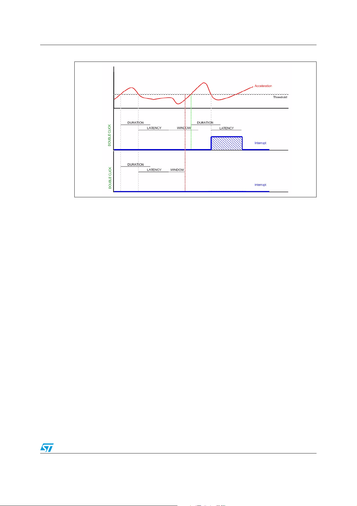
Figure 3. Double click recognition
(a)
(b)
In Figure 3(a) the double click event has been correctly recognized, while in Figure 3(b) the
interrupt has not been generated because the input acceleration exceeds the threshold after
the Window interval has expired.
5/15
Page 6

Register description AN2579
2 Register description
2.1 CLICK_CFG (38h)
Table 1. Register
- LIR Double_Z Single_Z Double_Y Single_Y Double_X Single_X
Table 2. Description
LIR Latch interrupt request to CLICK_SRC reg with the CLICK_SRC reg
refreshed by reading CLICK_SRC reg. Default value: 0
(0: interrupt request not latched; 1: interrupt request latched)
Double_Z Enable interrupt generation on double click event on Z axis. Default value: 0
(0: disable interrupt request; 1: enable interrupt request)
Single_Z Enable interrupt generation on single click event on Z axis. Default value: 0
(0: disable interrupt request; 1: enable interrupt request)
Double_Y Enable interrupt generation on double click event on Y axis. Default value: 0
(0: disable interrupt request; 1: enable interrupt request)
Single_Y Enable interrupt generation on single click event on Y axis. Default value: 0
(0: disable interrupt request; 1: enable interrupt request)
Double_X Enable interrupt generation on double click event on X axis. Default value: 0
(0: disable interrupt request; 1: enable interrupt request)
Single_X Enable interrupt generation on single click event on X axis. Default value: 0
(0: disable interrupt request; 1: enable interrupt request)
Table 3. Truth table
Double_Z / Y / X Single_Z / Y / X Click output
000
0 1 Single
1 0 Double
1 1 Single or double
2.2 CLICK_SRC (39h)
Table 4. Register
X IA Double_Z Single_Z Double_Y Single_Y Double_X Single_X
6/15
Page 7

AN2579 Register description
Table 5. Description
IA Interrupt active. Default value: 0
(0: no interrupt has been generated;
1: one or more interrupt events have been generated)
Double_Z Double click on Z axis event. Default value: 0
(0: no interrupt; 1: Double Z event has occurred)
Single_Z Single click on Z axis event. Default value: 0
(0: no interrupt; 1: Single Z event has occurred)
Double_Y Double click on Y axis event. Default value: 0
(0: no interrupt; 1: Double Y event has occurred)
Single_Y Single click on Y axis event.Default value: 0
(0: no interrupt; 1: Single Y event has occurred)
Double_X Double click on X axis event. Default value: 0
(0: no interrupt; 1: Double X event has occurred)
Single_X Single click on X axis event. Default value: 0
(0: no interrupt; 1: Single X event has occurred)
IA Interrupt active. Default value: 0
(0: no interrupt has been generated;
1: one or more interrupt events have been generated)
2.3 CLICK_THSY_X (3Bh)
Table 6. Register
THSy3 THSy2 THSy1 THSy0 THSx3 THSx2 THSx1 THSx0
Table 7. Description
THSy3, THSy0 Click threshold on Y axis. Default value: 0000
THSx3, THSx0 Click threshold on X axis. Default value: 0000
2.4 CLICK_THSZ (3Ch)
Table 8. Register
XXXXTHSz3THSz2THSz1THSz0
Table 9. Description
THSz3, THSz0 Click threshold on Z axis. Default value: 0000
From 0.5g(0001) to 7.5g(1111) with increments of 0.5g.
The THSx, THSy and THSz registers define the threshold which is used by the system to
start the click detection procedure. The threshold value is expressed over 4 bits as an
unsigned number.
7/15
Page 8

Register description AN2579
2.5 CLICK_TimeLimit (3Dh)
Table 10. Register
Dur7 Dur6 Dur5 Dur4 Dur3 Dur2 Dur1 Dur0
From 0 to 127.5 msec in increments of 0.5 msec.
Dur7 through Dur0 define the maximum time interval that can elapse between the start of
the click detection procedure (the acceleration on the selected channel exceeds the
programmed threshold) and when the acceleration goes back below the threshold.
2.6 CLICK_Latency (3Eh)
Table 11. Register
Lat7 Lat6 Lat5 Lat4 Lat3 Lat2 Lat1 Lat0
From 0 to 255 msec in increments of 1 msec.
Lat7 through Lat0 define the time interval that starts after the first click detection where the
click detection procedure is disabled, in cases where the device is configured for double
click detection.
2.7 CLICK_Window (3Fh)
Table 12. Register
Win7 Win6 Win5 Win4 Win3 Win2 Win1 Win0
From 0 to 255 msec in increments of 1 msec.
Win7 through Win0 define the maximum interval of time that can elapse after the end of the
latency interval in which the click detection procedure can start, in cases where the device is
configured for double click detection.
2.8 CTRL_REG3 [Interrupt CTRL register] (22h)
Table 13. Register
IHL PP_OD I2CFG2 I2CFG1 I2CFG0 I1CFG2 I1CFG1 I1CFG0
Table 14. Description
IHL Interrupt active high/low. Default value 0.
(0: active high; 1: active low)
PP_OD Push-pull/open drain selection on interrupt pad. Default value 0.
(0: push-pull; 1: open drain)
8/15
Page 9

AN2579 Register description
Table 14. Description (continued)
I2CFG2
I2CFG1
I2CFG0
I1CFG2
I1CFG1
I1CFG0
Data signal on Int2 pad control bits. Default value 000.
(see table below)
Data signal on Int1 pad control bits. Default value 000.
(see table below)
Table 15. Truth table
I1(2)_CFG2 I1(2)_CFG1 I1(2)_CFG0 Int1(2) Pad
0 0 0 GND
001FF_WU_1
010FF_WU_2
0 1 1 FF_WU_1 or FF_WU_2
100Data ready
1 1 1 Click interrupt
9/15
Page 10

Examples AN2579
3 Examples
The following figures show the click interrupt generation in different conditions. The
illustrations have been captured on a PC running the EK302DL GUI interface. The content
of the LIS302DL registers have been modified via the dedicated panel of the software
interface that allows the user to evaluate all the different settings and features of the click
embedded function. In the following examples, only the Y axis has been enabled for the click
interrupt generation.
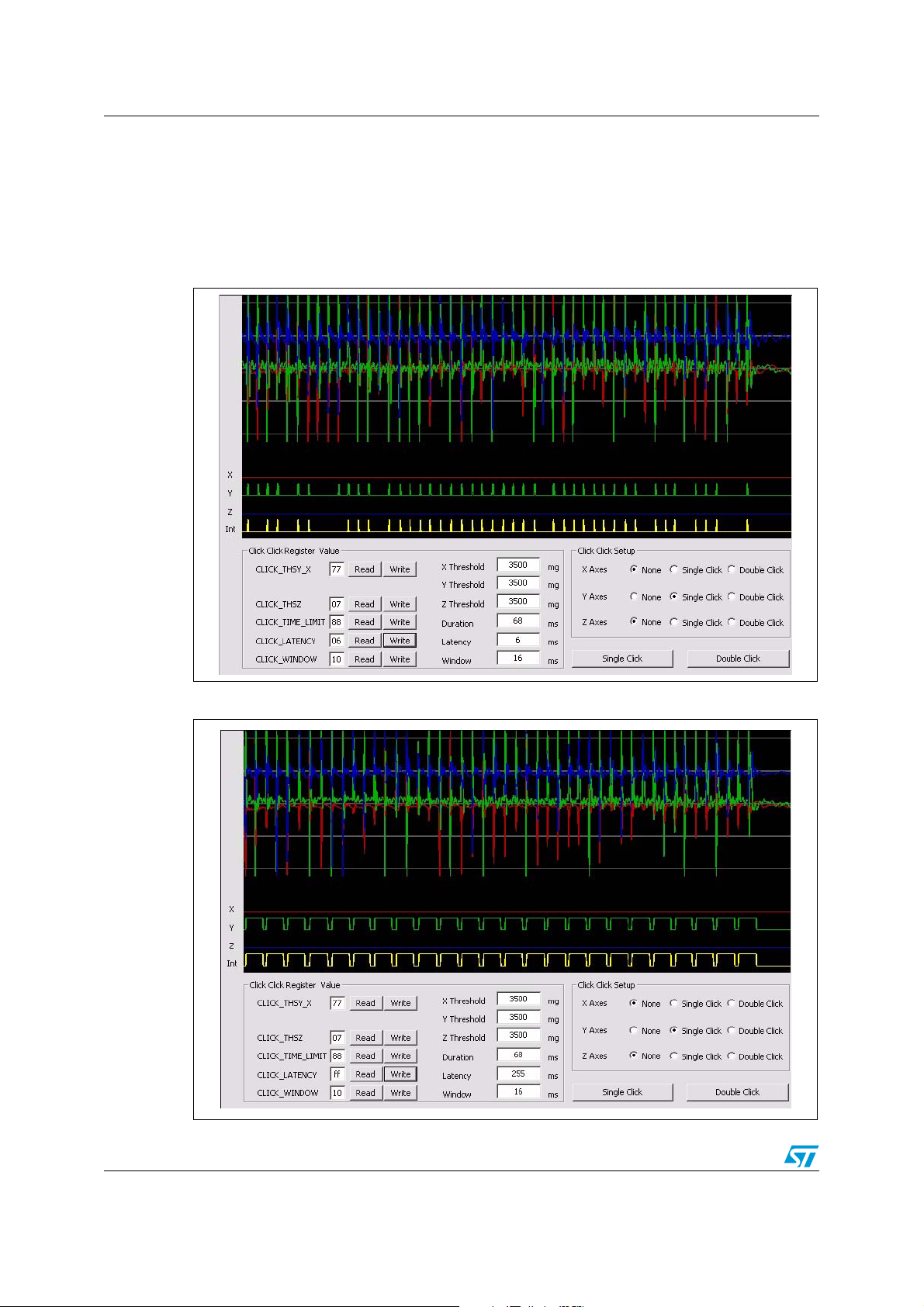
3.1 Playing with CLICK_TimeLimit
Figure 4 shows an acquisition carried out with CLICK_TimeLimit = 02h (1 ms). With this
setting, the single click recognition window is short and often the acceleration does not
return below the threshold in time.
In Figure 5 an acquisition done with CLICK_TimeLimit = FFh (127 ms) is shown. With this
setting the single click recognition window is longer, and it is easier for the event to be
recognized.
Figure 4. Short TimeLimit
10/15
Page 11

AN2579 Examples
Figure 5. Long TimeLimit
11/15
Page 12
Examples AN2579
3.2 Playing with CLICK_Latency
Figure 6 illustrates an acquisition done with CLICK_Latency = 06h (6 ms). With this setting
the device recognizes as a click nearly every acceleration peak. In Figure 7 an acquisition
carried out with CLICK_Latency = ffh (255 ms) is displayed. With this setting the device
recognizes as a click one peak in every two.
Figure 6. Short Latency
Figure 7. Long Latency
12/15
Page 13

AN2579 Examples
3.3 Playing with CLICK_Window
In cases of double click recognition, the CLICK _Latency + CLICK_Window defines the
maximum distance between two consecutive clicks to be recognized as double click event.
By fixing the latency to avoid spurious bouncing of the signal, one can play with the
CLICK_Window as with the “double-click speed” settings of the mouse properties on the
PC.
Figure 8 shows an acquisition done with CLICK_Window = 10h (10 ms). With this setting the
two consecutive peaks of acceleration are too far apart and the second one occurs outside
of the Window.
In Figure 9 an acquisition carried out with CLICK_Window = ffh (255 ms) is shown. With this
setting the device correctly generates the double click interrupt after the second acceleration
peak.
Figure 8. Short Window
13/15
Page 14

Revision history AN2579
Figure 9. Long Window
4 Revision history
Table 16. Document revision history
Date Revision Changes
17-Jan-2008 1 Initial release
14/15
Page 15

AN2579
Please Read Carefully:
Information in this document is provided solely in connection with ST products. STMicroelectronics NV and its subsidiaries (“ST”) reserve the
right to make changes, corrections, modifications or improvements, to this document, and the products and services described herein at any
time, without notice.
All ST products are sold pursuant to ST’s terms and conditions of sale.
Purchasers are solely responsible for the choice, selection and use of the ST products and services described herein, and ST assumes no
liability whatsoever relating to the choice, selection or use of the ST products and services described herein.
No license, express or implied, by estoppel or otherwise, to any intellectual property rights is granted under this document. If any part of this
document refers to any third party products or services it shall not be deemed a license grant by ST for the use of such third party products
or services, or any intellectual property contained therein or considered as a warranty covering the use in any manner whatsoever of such
third party products or services or any intellectual property contained therein.
UNLESS OTHERWISE SET FORTH IN ST’S TERMS AND CONDITIONS OF SALE ST DISCLAIMS ANY EXPRESS OR IMPLIED
WARRANTY WITH RESPECT TO THE USE AND/OR SALE OF ST PRODUCTS INCLUDING WITHOUT LIMITATION IMPLIED
WARRANTIES OF MERCHANTABILITY, FITNESS FOR A PARTICULAR PURPOSE (AND THEIR EQUIVALENTS UNDER THE LAWS
OF ANY JURISDICTION), OR INFRINGEMENT OF ANY PATENT, COPYRIGHT OR OTHER INTELLECTUAL PROPERTY RIGHT.
UNLESS EXPRESSLY APPROVED IN WRITING BY AN AUTHORIZED ST REPRESENTATIVE, ST PRODUCTS ARE NOT
RECOMMENDED, AUTHORIZED OR WARRANTED FOR USE IN MILITARY, AIR CRAFT, SPACE, LIFE SAVING, OR LIFE SUSTAINING
APPLICATIONS, NOR IN PRODUCTS OR SYSTEMS WHERE FAILURE OR MALFUNCTION MAY RESULT IN PERSONAL INJURY,
DEATH, OR SEVERE PROPERTY OR ENVIRONMENTAL DAMAGE. ST PRODUCTS WHICH ARE NOT SPECIFIED AS "AUTOMOTIVE
GRADE" MAY ONLY BE USED IN AUTOMOTIVE APPLICATIONS AT USER’S OWN RISK.
Resale of ST products with provisions different from the statements and/or technical features set forth in this document shall immediately void
any warranty granted by ST for the ST product or service described herein and shall not create or extend in any manner whatsoever, any
liability of ST.
ST and the ST logo are trademarks or registered trademarks of ST in various countries.
Information in this document supersedes and replaces all information previously supplied.
The ST logo is a registered trademark of STMicroelectronics. All other names are the property of their respective owners.
© 2008 STMicroelectronics - All rights reserved
STMicroelectronics group of companies
Australia - Belgium - Brazil - Canada - China - Czech Republic - Finland - France - Germany - Hong Kong - India - Israel - Italy - Japan -
Malaysia - Malta - Morocco - Singapore - Spain - Sweden - Switzerland - United Kingdom - United States of America
www.st.com
15/15
 Loading...