

Page 1

AN2540
Application note
EEPROM emulation in
STR91xF devices
Introduction
Replacing external EEPROM with emulated EEPROM from the embedded-Flash memory of
the microcontroller is a complex development. This application note is aimed at readers that
are already familiar with the techniques used to secure the content of evolutive information
in the external EEPROM of embedded applications.This application note explains the
differences between external/internal EEPROMs and embedded-Flash memory. It also
gives advice on how to replace external EEPROM with emulated-EEPROM using the onchip Flash memory of STR91xF devices.
This document also focuses on some embedded aspects in emulated-EEPROM data
storage, that are assumed to be known by the reader.
Overview
Electrically erasable and programmable read-only memory (EEPROM) is a key component
in many embedded applications requiring non-volatile storage of data that are updated at a
byte, half-word or word granularity during run time.
On the other hand, the microcontrollers used in those systems are more and more based on
embedded-Flash memory. To eliminate components, save silicon area and reduce system
cost, the STR91xF Flash memory could eventually replace the external EEPROM for
simultaneous code and data storage.
However unlike Flash memory, external EEPROM does not require a block erase operation
to free up space before data can be rewritten. A special software management is required to
store data into Flash memory.
Obviously the emulation software scheme depends on many factors including the EEPROM
reliability, Flash memory architecture and product requirements. Two approaches to
implementation are described in detail in this application note using the on-chip Flash
memory of the STR91xF microcontrollers.
June 2007 Rev 1 1/25
www.st.com
Page 2

Contents AN2540 - Application note
Contents
1 Embedded Flash memory vs. EEPROM: main differences . . . . . . . . . . 5
1.1 Difference in write access time . . . . . . . . . . . . . . . . . . . . . . . . . . . . . . . . . . 5
1.2 Difference in writing method . . . . . . . . . . . . . . . . . . . . . . . . . . . . . . . . . . . . 5
1.3 Difference in erase time . . . . . . . . . . . . . . . . . . . . . . . . . . . . . . . . . . . . . . . 6
2 Appropriate solution for Emulated EEPROM in the STR91xF . . . . . . . . 7
2.1 STR91xF on-chip Flash memory features . . . . . . . . . . . . . . . . . . . . . . . . . 7
2.2 STR91xF Flash memory library . . . . . . . . . . . . . . . . . . . . . . . . . . . . . . . . . 7
3 Implementing the EEPROM emulation . . . . . . . . . . . . . . . . . . . . . . . . . . 8
3.1 Principle . . . . . . . . . . . . . . . . . . . . . . . . . . . . . . . . . . . . . . . . . . . . . . . . . . . 8
3.2 1st method . . . . . . . . . . . . . . . . . . . . . . . . . . . . . . . . . . . . . . . . . . . . . . . . . 9
3.2.1 Application example . . . . . . . . . . . . . . . . . . . . . . . . . . . . . . . . . . . . . . . . . 9
3.2.2 EEPROM software description . . . . . . . . . . . . . . . . . . . . . . . . . . . . . . . 11
3.3 2nd method . . . . . . . . . . . . . . . . . . . . . . . . . . . . . . . . . . . . . . . . . . . . . . . 15
3.3.1 Application example . . . . . . . . . . . . . . . . . . . . . . . . . . . . . . . . . . . . . . . . 15
3.3.2 EEPROM software description . . . . . . . . . . . . . . . . . . . . . . . . . . . . . . . 16
3.4 Program execution . . . . . . . . . . . . . . . . . . . . . . . . . . . . . . . . . . . . . . . . . . 17
4 Embedded application aspects . . . . . . . . . . . . . . . . . . . . . . . . . . . . . . . 18
4.1 Data granularity management . . . . . . . . . . . . . . . . . . . . . . . . . . . . . . . . . 18
4.1.1 Programming on a word-by-word basis . . . . . . . . . . . . . . . . . . . . . . . . . 18
4.1.2 Programming on a byte-by-byte basis . . . . . . . . . . . . . . . . . . . . . . . . . . 18
4.2 Wear-leveling: Flash endurance improvement . . . . . . . . . . . . . . . . . . . . . 19
4.2.1 Application example . . . . . . . . . . . . . . . . . . . . . . . . . . . . . . . . . . . . . . . . 19
4.3 Sector header recovery in case of power loss . . . . . . . . . . . . . . . . . . . . . 20
4.4 Emulated EEPROM parameters . . . . . . . . . . . . . . . . . . . . . . . . . . . . . . . 21
4.4.1 Program/Erase parameter cycling . . . . . . . . . . . . . . . . . . . . . . . . . . . . . 21
4.4.2 Program timing . . . . . . . . . . . . . . . . . . . . . . . . . . . . . . . . . . . . . . . . . . . 22
5 Conclusion . . . . . . . . . . . . . . . . . . . . . . . . . . . . . . . . . . . . . . . . . . . . . . . . 23
6 Revision history . . . . . . . . . . . . . . . . . . . . . . . . . . . . . . . . . . . . . . . . . . . 24
2/25
Page 3

AN2540 - Application note List of tables
List of tables
Table 1. Differences between Embedded Flash memory and EEPROM . . . . . . . . . . . . . . . . . . . . . . 5
Table 2. EepromFormat . . . . . . . . . . . . . . . . . . . . . . . . . . . . . . . . . . . . . . . . . . . . . . . . . . . . . . . . . . 12
Table 3. FindValidSector . . . . . . . . . . . . . . . . . . . . . . . . . . . . . . . . . . . . . . . . . . . . . . . . . . . . . . . . . 12
Table 4. ReadVariable . . . . . . . . . . . . . . . . . . . . . . . . . . . . . . . . . . . . . . . . . . . . . . . . . . . . . . . . . . . 12
Table 5. WriteVariable . . . . . . . . . . . . . . . . . . . . . . . . . . . . . . . . . . . . . . . . . . . . . . . . . . . . . . . . . . . 12
Table 6. WriteVerifyVariableFull . . . . . . . . . . . . . . . . . . . . . . . . . . . . . . . . . . . . . . . . . . . . . . . . . . . . 13
Table 7. EepromSectorTransfer . . . . . . . . . . . . . . . . . . . . . . . . . . . . . . . . . . . . . . . . . . . . . . . . . . . . 14
Table 8. Status combinations and actions to be taken . . . . . . . . . . . . . . . . . . . . . . . . . . . . . . . . . . . 21
Table 9. Write time related to the current implementation . . . . . . . . . . . . . . . . . . . . . . . . . . . . . . . . 22
Table 10. Document revision history . . . . . . . . . . . . . . . . . . . . . . . . . . . . . . . . . . . . . . . . . . . . . . . . . 24
3/25
Page 4

List of figures AN2540 - Application note
List of figures
Figure 1. Header field status switching between sector0 and 1. . . . . . . . . . . . . . . . . . . . . . . . . . . . . . 8
Figure 2. Sector swap scheme: Sector1 erased . . . . . . . . . . . . . . . . . . . . . . . . . . . . . . . . . . . . . . . . 10
Figure 3. Sector swap scheme: Sector0 erased . . . . . . . . . . . . . . . . . . . . . . . . . . . . . . . . . . . . . . . . 11
Figure 4. 1st method: WriteVariable flowchart . . . . . . . . . . . . . . . . . . . . . . . . . . . . . . . . . . . . . . . . . . 13
Figure 5. Data storage procedure . . . . . . . . . . . . . . . . . . . . . . . . . . . . . . . . . . . . . . . . . . . . . . . . . . . 15
Figure 6. Data update flow . . . . . . . . . . . . . . . . . . . . . . . . . . . . . . . . . . . . . . . . . . . . . . . . . . . . . . . . . 16
Figure 7. 2nd method: WriteVariable flowchart . . . . . . . . . . . . . . . . . . . . . . . . . . . . . . . . . . . . . . . . . 17
Figure 8. WriteOnebyte function description . . . . . . . . . . . . . . . . . . . . . . . . . . . . . . . . . . . . . . . . . . . 19
Figure 9. Sector swap scheme with four sectors . . . . . . . . . . . . . . . . . . . . . . . . . . . . . . . . . . . . . . . . 20
4/25
Page 5

AN2540 - Application note Embedded Flash memory vs. EEPROM: main differences
1 Embedded Flash memory vs. EEPROM: main
differences
Before describing the proposed concept for EEPROM emulation, it is important to
remember the main differences between the embedded Flash memory of a microcontroller
and serial external EEPROMs. These differences are the same for any microcontroller (that
is they are not specific to STR91xF products). They are summarized in Ta bl e 1 .
Table 1. Differences between Embedded Flash memory and EEPROM
Feature External EEPROM
A few ms
Write time
Erase time N/A seconds (e.g.: 1.5 s)
Write method
Read access
– random byte: 5 to 10 ms
– page: equivalent to a hundred µs per
word (5 to 10 ms per page)
Once started, is not CPU-dependent,
needs only proper supply.
Serial: a hundred µs
random word: 92 µs
page: 22.5 µs/byte
1.1 Difference in write access time
As the Flash memory has a shorter write access time, critical parameters can be stored
faster into the emulated EEPROM than into an external serial EEPROM. The use of the
Flash memory therefore improves the system robustness.
Emulated EEPROM using on-chip Flash
memory
A few µs
(e.g.: 20 µs per 16-bit word)
Once started, is CPU-dependent: a CPU
reset will stop the write process even if the
supply stays within specifications.
Parallel: a hundred ns
very few CPU cycles per 16-bit word.
1.2 Difference in writing method
One of the major differences between external and emulated EEPROM for embedded
applications is the writing method.
● Standalone external EEPROM: once started by the CPU, the writing of a word cannot
be interrupted by a CPU reset. Only a power supply failure can interrupt the writing
process, so properly sizing the decoupling capacitors can secure the write process to a
standalone EEPROM.
● Emulated EEPROM from an embedded Flash memory: once started by the CPU, the
writing can be interrupted by a power failure and by a CPU reset. This difference should
be analyzed by system designers to understand the possible impact(s) in their
applications, and to determine a proper method to handle them.
5/25
Page 6

Embedded Flash memory vs. EEPROM: main differences AN2540 - Application note
1.3 Difference in erase time
The difference in erase time is the other major difference between standalone EEPROM and
emulated EEPROM with embedded Flash memory. Unlike Flash memory, EEPROM does
not require a block erase operation to free up space before writing. Moreover, as the erase
process of a block in the Flash memory takes a few seconds, power shut-down and other
spurious events that may interrupt the erase process (e.g.: reset) should be considered
when designing the Flash memory management software. This means that to design a
robust Flash memory management software it is necessary to have a good understanding of
the Flash memory erase process.
6/25
Page 7

AN2540 - Application note Appropriate solution for Emulated EEPROM in the STR91xF
2 Appropriate solution for Emulated EEPROM in the
STR91xF
The STR91xF microcontrollers support the hardware and software architecture necessary
to emulate EEPROM memory using the on-chip Flash memory.
2.1 STR91xF on-chip Flash memory features
■ The STR91x internal Flash memory consists of two banks: Main Flash memory (Bank 0)
and Secondary Flash memory (Bank 1). The Main Flash memory is up to 512 Kbytes in
size and includes up to eight 64-Kbyte sectors. The Secondary Flash memory is 32
Kbytes in size and consists of four 8-Kbyte sectors, it can be useful for the wear-leveling
feature (refer to Section 4.2).
■ One of the STR9 embedded Flash memory features is Read-while-Write (RWW) Dual
Bank operations. This means that the Main Flash memory (Bank0) can be used for code
storage and the smaller Secondary Flash memory, for data storage (EEPROM
emulation).
■ The Flash memory can be erased on a sector or bank basis, and programmed on a 16-
bit half-word basis.
■ Each bank can be programmed and erased over 100 000 cycles.
■ 20-year data retention.
■ Each sector can be individually protected and unprotected against program and erase
operations.
■ As the Flash memory has a shorter write access time, critical parameters can be stored
faster in the emulated EEPROM than in an external serial EEPROM.
■ Interrupt servicing during program/erase is possible.
■ CPU program does not need to be copied into RAM during program/erase: RAM less used
to perform EEPROM emulation.
■ Program/Erase Suspend and Resume commands supported. That is, Flash memory
sector erase may be suspended while data is read from other sectors in the same Flash
memory bank, and then resumed after reading.
2.2 STR91xF Flash memory library
The Flash memory programming library is a set of optimized C routines. It contains all that is
needed to program the Flash memory embedded in STR9 devices.
The Flash memory library contains the following source files:
■ 91x_fmi.c, that contains the function codes
■ 91x_fmi.h, that contains the function prototypes
To use the functions provided by the Flash memory library, these two files must be added to
the project. With the STR9 software (SW) library (FMI driver) it is easy to implement the
EEPROM emulation software.
7/25
Page 8
Implementing the EEPROM emulation AN2540 - Application note
3 Implementing the EEPROM emulation
3.1 Principle
This emulation is performed in various ways by considering the Flash memory limitations
and the product requirements. Two approaches are described below in detail. Both require a
minimum of two Flash memory sectors of identical size, that are allocated to non-volatile
data. One that is initially erased and can be programmed byte by byte, and the other that is
ready to take over when the first sector needs to be garbage-collected.
Since the STR91xF on-chip Flash memory can be programmed on a 16-bit half-word basis,
the data granularity in this implementation is 16 bits.
A header field that occupies the first 16-bit half word of each sector indicates the sector
status.
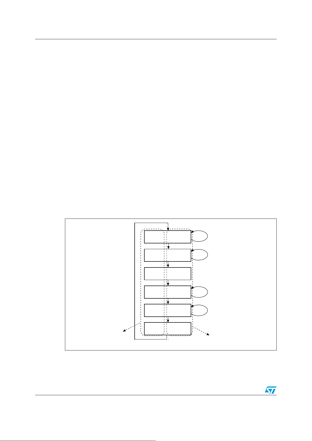
Each sector has four possible states:
● ERASED: The sector is empty.
● RECEIVE_DATA: The sector is receiving data from the full sector.
● VALID_SECTOR: The sector contains valid data and its state will not change until valid
data are completely transferred to the erased sector.
● TRANSFER_COMPLETE: Transfer of data to the other sector is finished and this
sector is no longer in use. The system can then erase it and prepare it for future data.
Figure 1. shows how to switch from one state to another for both sectors.
Figure 1. Header field status switching between sector0 and 1
Write data in sector0
Copy data from sector0
to sector1
Write data in sector1
Copy data from sector1
to sector0
States related to sector1
States related to sector0
Valid0 Erased1
Sector0 Full
Valid0 Receive1
Transfer data from sector0 to sector1 complete
Transfer_
complete0
Erased0 Valid1
Receive0 Valid1
Valid0
Valid1
Erase0
Sector1 Full
Transfer data from sector1 to sector0 complete
Transfer_
complete1
Erase1
ai14085
8/25
Page 9

AN2540 - Application note Implementing the EEPROM emulation
3.2 1st method
Parameter records stored in EEPROM vary in size and update frequency. Users using this
method would usually know the update frequency in advance.
In this method, sector0 and sector1 in Bank1 are used. These Flash memory sectors are
write-accessed in order to store several non-volatile variables. For this purpose, they have to
be divided identically into several parts, one per variable. The size of the memory space
allocated to each variable depends on the variable update frequency. The first 16-bit value
of each variable is stored at the base address of the memory space allocated to the
variable. When the variable is updated, the new value is stored at the next available
address: Base address + 2, base address + 4 and so on until no room remains in the
allocated memory space.
st
The 1
● At least two boot Flash memory sectors have to be used, more if possible for wear
● Minimum use of SRAM
● Simple and easily updatable code model
● User API consisting of EepromFormat, FindValidSector, WriteVariable, ReadVariable.
● Clean-up and internal data management transparent to the user
● Code in Main Flash memory, data storage in Secondary Flash memory
method Emulation driver meets the following requirements:
leveling (refer to Section 4.2)
3.2.1 Application example
Let us assume that in sector0, three variables: A, B and C, will be stored and updated.
■ The first variable A value is stored at t
■ The second variable B value is stored at t
■ The third variable C value is stored at t
In a typical application, the majority of non-volatile data are seldom updated, only a few data
are updated more frequently.
Let us consider t
A is updated more often than B. So more memory space should be allocated to C than to A
and B, and A should have more space than B (refer to Figure 2).
< tA< tB. This means that C is updated more often than A and B, and that
C
and variable A(t) is updated every tA.
0
and variable B(t) is updated every tB.
1
and variable C(t) is updated every tC.
2
9/25
Page 10

Implementing the EEPROM emulation AN2540 - Application note
Figure 2. Sector swap scheme: Sector1 erased
0x0000 1FFF
C(t) values
Update
B(t) values
Update
A(t) values
Update
0x0000 0000
C(t0 + p × tC)
C(t0)
B(t0 + m × tB)
B(t0)
A(t0 + n × tA)
A(t0 + tA)
A(t0)
Sector0 Header
Sector0
(Erase one when using the other)
0x0000 3FFF
C(t) values
B(t) values
A(t) values
0x0000 2000
Sector swap
C(t0 + p × tC)
C(t0)
B(t0 + m × tB)
B(t0)
A(t0 + n × tA)
A(t0 + tA)
A(t0)
Sector1 Header
Sector1 Erased
In this application, sector0 is divided up as follows:
■ 0x0000 0002 - 0x0000 04FF memory space is allocated to variable A
■ 0x0000 0500 - 0x0000 0510 memory space is allocated to variable B
■ 0x0000 0511 - 0x0000 1FFF memory space is allocated to variable C
ai14086
In sector0, variables are stored until there the memory space left is not large enough to be
allocated to another variable (case of variable A in the following example).
Example: Let us assuming that variable A is to be updated at time t0 + (n+1) × tA to A(t0 +
(n+1) × tA). Addresses from 0x0000 0002 to 0x0000 04FF are all full, the next value is then
stored in the base address of the space allocated to variable A in sector1.
The latest stored values of all other variables (B and C) are transferred from their current
location in sector0 to the base address of their allocated space in sector1. After the transfer
of all variables is complete, sector0 is erased.
Variables are then stored and updated in sector1 in the same way as described for sector0.
When there is not enough memory space left for one of these variables in sector1, the
variables are transferred back to sector0 (now empty) as described above and so on. This
process is illustrated in Figure 3.
10/25
Page 11

AN2540 - Application note Implementing the EEPROM emulation
Figure 3. Sector swap scheme: Sector0 erased
0x0000 1FFF
C(t0 + p × tC)
C(t) values
Update
B(t) values
Update
A(t) values
Update
0x0000 0000
C(t0)
B(t0 + m × tB)
B(t0)
A(t0 + n × tA)
A(t0 + tA)
A(t0)
Sector0 Header
Sector0 Erased
3.2.2 EEPROM software description
0x0000 3FFF
C(t) values
B(t) values
A(t) values
0x0000 2000
(Erase one when using the other)
Sector swap
C(t + p × tC)
0
B(t0 + m × tB)
A(t + (n + 1) × tA)
0
Sector1 Header
Sector1
ai14087
This section describes the driver implemented for EEPROM emulation using the STR91xF
Flash library provided by STMicroelectronics.
A demonstration program is also supplied to demonstrate and test the EEPROM Emulation
driver using the three variables A, B and C already defined.
The project contains three source files in addition to the FMI library source files:
● eeprom.c: containing C code for the following routines:
EepromFormat()
WriteVariable()
ReadVariable()
FindValidSector()
WriteVerifyVariableFull()
EepromSectorTransfer()
● eeprom.h: Containing the routines’ prototypes and some declarations.
● main.c: This application program is an example using the routines described in
eeprom.c.
11/25
Page 12

Implementing the EEPROM emulation AN2540 - Application note
3.2.2.1 User API definition
Table 2. EepromFormat
Function Name EepromFormat
Function Prototype
u8 EepromFormat(void);
Behavior Description
This function erases sector0 and sector1 and writes a
VALID_SECTOR header to sector0.
Input Parameter None
Return Parameter Status of the operation.
Called functions FMI_EraseSector,FMI_WaitForLastOperation,FMI_WriteHalfWord
Table 3. FindValidSector
Function Name FindValidSector
Function Prototype
Behavior Description
u8 FindValidSector(u8 operation);
This function reads both sector’s headers and returns the sector
number which contains valid data.
A byte indicating that we are looking for a valid sector for write or read
Input Parameter
operation(READ_FROM_VALID_SECTOR or
WRITE_IN_VALID_SECTOR
Return Parameter Sector number.
Called functions FMI_ReadWord.
Table 4. ReadVariable
Function Name ReadVariable
Function Prototype
u16 ReadVariable(u8 index, u32 *T);
This function reads variable data. Only last update is read. The
Behavior Description
function enters a loop in which it reads the variable entries until the
last one is found. Finally, the data is returned.
Input Parameter
– index: variable identifier
– T: variable array
Return Parameter Returns 16-bit read data on success or error code on failure.
Called functions FindValidSector.
Table 5. WriteVariable
Function Name WriteVariable
Function Prototype
u8 WriteVariable(u8 index, u32 *T, u16 data);
Behavior Description This function is called by the user application to update a variable
– index: variable identifier
Input Parameter
– T: variable array
– data: 16-bit data to be written
Return Parameter Returns 1 on success or error code on failure
Called functions WriteVerifyVariableFull, EepromSectorTransfer.
12/25
Page 13

AN2540 - Application note Implementing the EEPROM emulation
The procedure of updating a variable entry in the EEPROM is shown in Figure 4.
Figure 4. 1
FindValidSector()
WriteVerifyVariableFull()
EepromSectorTransfer()
Table 6. WriteVerifyVariableFull
st
method: WriteVariable flowchart
Function call
ReadVariable()
Copy each latest element of
each available record by
reading from bottom taking
into account the new
updated element.
Change the active sector
Erase previous active sector
Function Name WriteVerifyVariableFull
Function Prototype
u16 WriteVerifyVariableFull(u8 index, u32 *T, u16Data);
End
Add element request
Find Valid sector
Yes No
full
current record
Add new element at
the 1st empty element
place in the current
record of active sector
End
ai14088
Behavior
Description
If a write operation takes place, the write process must either update a variable,
or create the first instance of a variable.
– variable index, in the demonstration example provided: (0 for A, 1 for B or 2
Input Parameter
for C).
– T: variable Array
– 16-bit data to be written
Return Parameter Returns 1 on success or 0x80 if variable is full or Flash error code
Called functions FindValidSector,FMI_ReadWord,FMI_WriteHalfWord
If the data to be written is equal to 0xFFFF, it is necessary to find the last data equal to
0xFFFF and to write 0x0000 into the next location to indicate that 0xFFFF represents data
and not a blank location. If the data to be written is different from 0xFFFF, it is then written to
the last location that contains 0xFFFFh (the following location should not contain 0x0000).
This function returns 0 on success, VARIABLE_FULL if there is not enough memory space
for a variable update, or a Flash error code indicating an operation failure (erase or
program).
13/25
Page 14

Implementing the EEPROM emulation AN2540 - Application note
Table 7. EepromSectorTransfer
Function Name EepromSectorTransfer
Function Prototype
Behavior Description
Input Parameter
Return Parameter Returns 1 on success or error code on failure
Called functions
u8 EepromSectorTransfer(u8 index, u32 *T, u16 data);
It transfers the most recent data (Last variable updates) plus the new
data from a full sector to an empty one.
– index: variable identifier (0, 1, 2...)
– T: variable array
– data: 16-bit data to be written
FindValidSector,FMI_WriteHalfWord, WriteVerifyVariableFull,
ReadVariable, FMI_EraseSector.
At the beginning, the function determines the active sector which is the sector to be
transferred from. The new sector header field is defined and written (new sector status is
RECEIVE_DATA given that it is in the process of receiving data). When the data transfer is
complete, the new sector header is marked VALID_SECTOR and the old one
TRANSFER_COMPLETE. At the end, the old sector is erased.
3.2.2.2 Key features of the 1st method
– User-configured emulated EEPROM size.
– The number of Flash program/erase cycles used can be minimized by permanently
allocating a large memory space to the most frequently updated non-volatile data
variables.
– ReadVariable and WriteVariable functions to access variables.
– The whole available memory space is used to store data: no need for virtual
addresses.
– Fast read access to any variable since this simply implies going to the corresponding
allocated memory space.
– Interrupt servicing during program/erase is possible.
14/25
Page 15

AN2540 - Application note Implementing the EEPROM emulation
3.3 2
nd
method
Generally when using this method, the user does not known in advance the update
frequency of the variables. To emulate the EEPROM, two sector data structures are used.
Each data element is defined by a virtual address and its value to be stored into Flash
memory locations for subsequent retrieval or update. When data is modified, the data
associated with the earlier virtual address is stored into a new Flash memory location.
During data retrieval, the modified data, in the latest Flash memory location is returned.
Figure 5. Data storage procedure
EEPROM Data (16 bits)
EEPROM Virtual @ (16 bits)
EEPROM element = 32-bit word
32 bits
2048 elements (8 KB)
sector1sec tor0
ai14089
3.3.1 Application example
This example shows three EEPROM variables with the following virtual addresses:
● var1: AAAAh
● var2: 5555h
● var3: DDAAh
The data update flow is shown in Figure 6.
15/25
Page 16

Implementing the EEPROM emulation AN2540 - Application note
Figure 6. Data update flow
Sector0 Sector1
FF FF
FF FF
FF FF
FF FF
FF FF
FF FF
FF FF
FF FF
FF FF
FF FF
FF FF
FF FF
FF FF
FF FF
FF FF
FF FF
FF FF
Active sector = sector0
Active sector = sector0
FF FF
Add var2
Sector0 Sector1
FF FF
12 32
FF FF
DD AA
FF FF
12 45
FF FF
DD AA
FF FF
BC BC
FF FF
AA AA
FF FF
34
34
FF FF
55 55
FF FF
FF FF
=3434h
Add var3
=1232h
Active sector = sector0
Active sector = sector0
Sector0 Sector1
12 32
FF FF
DD AA
FF FF
FF FF
FF FF
FF FF
FF FF
FF FF
FF FF
FF FF
FF FF
FF FF
FF FF
FF FF
FF FF
FF FF
FF FF
Sector0 Sector1
12 32
FF FF
FF FF
DD AA
FF FF
FF FF
32 32
FF FF
DD AA
FF FF
22 45
FF FF
DD AA
BD BD
FF FF
AA AA
54 54
55 55
FF FF
Add var3
=1245h
Active sector = sector0
Add var2
=6464h
Active sector = sector0
Sector0 Sector1
FF FF
12 32
FF FF
DD AA
FF FF
12 45
FF FF
DD AA
FF FF
FF FF
FF FF
FF FF
FF FF
FF FF
FF FF
FF FF
FF FF
FF FF
Sector0 Sector1
12 32
64 64
55 55
DD AA
22 45
DD AA
32 32
BD BD
DD AA
22 45
AA AA
DD AA
FF FF
BD BD
FF FF
AA AA
54 54
55 55
FF FF
Sector0 Sector1
FF FF
12 32
FF FF
DD AA
FF FF
12 45
FF FF
Add var1
DD AA
FF FF
BC BC
=BCBCh
Active sector = sector0
Erase
sector0
Active sector = sector0
The most recent data (Last
variable updates) are transferred
from sector0(as full sector) to
sector1 (as empty sector).
FF FF
AA AA
FF FF
FF FF
FF FF
FF FF
FF FF
FF FF
Sector0 Sector1
FF FF
FF FF
FF FF
FF FF
FF FF
FF FF
FF FF
FF FF
FF FF
FF FF
FF FF
FF FF
FF FF
FF FF
FF FF
FF FF
FF FF
FF FF
FF FF
ai14090
3.3.2 EEPROM software description
The user API function naming is the same as in the 1st method routines, the main
differences are shown in the WriteVariable flowchart given in Figure 7.
16/25
Page 17

AN2540 - Application note Implementing the EEPROM emulation
Figure 7. 2nd method: WriteVariable flowchart
Add element request
Function call
FindValidSector()
WriteVerifyVariableFull()
ReadVariable()
EepromSectorTransfer()
End
Copy all current elements by
reading the active sector
from the bottom, taking
into account the new
updated element.
Change the active sector
Erase previous active sector
Find Valid sector
End
Check
value
Yes No
current active
sector
same different
full
Add new element at
the 1st empty element
place in the current
active sector
3.3.2.1 Key features of the 2nd method
– User-configured emulated EEPROM size.
– Increased Flash memory endurance: Sector erased only once it is full.
– Non-volatile data variables can be updated infrequently
– No need to perform a write operation if the updated value is the same.
– Interrupt servicing during program/erase is possible.
End
ai14091
3.4 Program execution
Independently of the implementation scheme, the STR91xF internal Flash memory offers
the ability to update a bank while code is executed from the other bank. Therefore, there is
no need to transfer Flash memory operations (Program/Erase) to RAM. However when the
CPU frequency is higher then 25 MHZ it is recommended to copy some routines into RAM
This means that before erasing and programming, a few software routines have to be copied
from the Flash memory into the on-chip RAM. Should be copied at least the routines used
for the erase and program operations, and the routines that run while the erase or program
operation is ongoing.
17/25
Page 18

Embedded application aspects AN2540 - Application note
4 Embedded application aspects
This section gives some advice on how to overcome software limitations in embedded
applications and to fulfill the needs of different applications.
4.1 Data granularity management
The emulated EEPROM can be used in embedded applications where non-volatile storage
of data updated with a byte, half-word or word granularity is required. It generally depends
on the user requirements and Flash architecture, such as stored data length, write access,
etc.
The STR91xF on-chip Flash memory allows 16-bit, half-word programming. Data can
however be programmed by bytes or words by using some software techniques.
4.1.1 Programming on a word-by-word basis
To write 32 bits of data "FMI_Data" to the desired Flash memory address "FMI_Address" in
Bank1 for example, the process is the following:
■ Write the LSB part of the data (the first two bytes) to the desired Flash memory address.
■ Write the MSB part of the data (the last two bytes) to the Flash memory address
incremented twice.
u16 LSB=FMI_Data;
u16 MSB= FMI_Data >>16;
FMI_WriteHalfWord ( FMI_Address, LSB);
FMI_WaitForLastOperation(FMI_BANK_1);
FMI_WriteHalfWord ( FMI_Address+2,
MSB);FMI_WaitForLastOperation(FMI_BANK_1);
4.1.2 Programming on a byte-by-byte basis
Writing by bytes offers the user the possibility to cover the entire memory space and,
therefore, to store more data. The performance may however be reduced.
A simple example can be useful to understand how to implement such a feature.
Let us assume for example that we want to write one byte of data "0xDD" into Bank1 at the
FMI_Address. This can be achieved as follows:
If FMI_Address is even, then 0xFFDD is written. If FMI_Address is odd, 0xDDFF is written.
The generic scheme is shown in Figure 8.
18/25
Page 19

AN2540 - Application note Embedded application aspects
Figure 8. WriteOnebyte function description
void WriteVariable(u32 FMI_Address,u8 FMI_Data)
{
if (FMI_Address &1)
{
FMI_WriteHalfWord(FMI_Address,((FMI_Data << 8) | 0xFF));
FMI_WaitForLastOperation(FMI_BANK_1);
}
else
{
FMI_WriteHalfWord(FMI_Address,(0xFF00 |FMI_Data));
FMI_WaitForLastOperation(FMI_BANK_1);
}
}
The above function is used to write the "FMI_Data" data byte to the "FMI_Address" address.
4.2 Wear-leveling: Flash endurance improvement
In the STR91xF on-chip Flash memory, each sector can be programmed or erased reliably
over 100 000 times.
For write-intensive applications that use more than two sectors (3 or 4) for the emulated
EEPROM, it is recommended to implement a wear-leveling algorithm to monitor and
distribute the number of write cycles among the sectors.
When no wear-leveling algorithm is used, the sectors are not used at the same rate. Sectors
with long-lived data do not endure as many write cycles as sectors that contain frequently
updated data. The wear-leveling algorithm ensures that equal use is made of all the
available write cycles for each sector.
4.2.1 Application example
In this example, in order to enhance the emulated EEPROM capacity, four sectors will be
used.
To implement the wear-leveling algorithm with the 2
following: when sector n is full, switch to sector n+1. Sector n is then garbage-collected. Let
us consider the four sectors of the example: when sector3 is full, the device goes back to
sector0, then sector 3 is garbage-collected and so on (refer to Figure 9.).
nd
method scheme, the procedure is the
19/25
Page 20

Embedded application aspects AN2540 - Application note
Figure 9. Sector swap scheme with four sectors
Sector0
12 32
DD AA
FF FF
FF FF
FF FF
FF FF
FF FF
FF FF
FF FF
Active sector
Sector1 Sector2 Sector3
FF FF
FF FF
FF FF
FF FF
FF FF
FF FF
FF FF
FF FF
FF FF
Erased Erased Erased
FF FF
FF FF
FF FF
FF FF
FF FF
FF FF
FF FF
FF FF
FF FF
FF FF
FF FF
FF FF
FF FF
FF FF
FF FF
FF FF
FF FF
FF FF
ai14092
The previous algorithm can be implemented in the FindValidSector(...) function.
4.3 Sector header recovery in case of power loss
Data or sector header corruption is possible in case of a power loss during a variable
update, a sector erase or a transfer.
To detect this corruption and recover it, an initialization routine should be called immediately
after power-up.
After power loss, this routine is used to check the sector header status and to perform repair
if necessary. There are 16 possible status combinations, half of which are invalid. The
following table shows the actions that should be taken based on the sector states upon
power-up.
20/25
Page 21

AN2540 - Application note Embedded application aspects
Table 8. Status combinations and actions to be taken
Sector 0
Sector 1
ERASED RECEIVE_DATA VALID_DATA
TRANSFER
COMPLETE
ERASED
RECEIVE_DATA
VALID_ DATA
TRANSFER
COMPLETE
Invalid state so
erase both
sectors and
format sector 0
Invalid state:
erase both
sectors and
format sector 0
Use sector 1 as
valid sector and
erase sector 0
Invalid state:
erase both
sectors and
format sector 0
Invalid state so
erase both
sectors and
format sector 0
Invalid state:
erase both
sectors and
format sector 0
Use sector 1 as
valid sector &
erase sector 0 &
transfer data from
sector1 to sector0
Use sector 0 as
valid sector and
erase sector 1
4.4 Emulated EEPROM parameters
4.4.1 Program/Erase parameter cycling
Use sector 0 as
valid sector and
erase sector 1
Use sector 0 as
valid sector &
erase sector1 &
transfer data from
sector0 to sector1
Invalid state:
erase both sectors
and format
sector0
Use sector 0 as
valid sector and
erase sector 1
Invalid state: erase
both sectors and
format sector 0
Use sector 1 as valid
sector & erase sector 0
Use sector 1 as valid
sector and erase
sector 0
Invalid state: erase
both sectors and
format sector 0
One program/erase cycle consists of one or more write accesses and one sector erase
operation.
When the EEPROM technology is used, each byte can be programmed and erased a finite
number of times, typically in the range of 10 000 to 100 000.
However, when the Flash memory is used, the minimum erase size is the sector and the
number of Program/Erase cycles applied to a sector is the number of erase cycles. The
STR91xF electrical characteristics guarantee 100 000 Program/Erase cycles per sector.
Generally the maximum life of the EEPROM is thereby limited to the update rate of the most
frequently written parameter.
In the 1
st
scheme application example, two sectors of 8 Kbytes are used and programming
is done on a 16-bit half-word basis. If we consider that the memory space allocated to
variable C is always filled before the memory spaces allocated to variables A and B, the
expected number of erase cycles depends on variable C. As 6896 bytes are allocated to C,
the variable can be updated 3448 times before it is switched to the other sector and the first
sector is erased. Two sectors are used that can be erased 100 000 times so the total
number of cycles we can expect for C is:
3448 × 2 × 100 000 = 689 600 000 cycles.
21/25
Page 22

Embedded application aspects AN2540 - Application note
4.4.2 Program timing
The following table gives an idea about the emulated EEPROM write time related to the
current implementation.
It is clear that updating a variable with the 1
nd
2
method scheme since only the corresponding allocated memory space is accessed in
the first case and not the whole sector.
Table 9. Write time related to the current implementation
Implemented scheme
Write time (typical) Write time (max)
1st method scheme 20 µs 300 ms
nd
method scheme 30 µs
2
1. This is the time taken to update a variable that makes a call to the EepromSectorTransfer(..) function. It is
nearly equal to the sector erase time.
st
method scheme takes less time than with the
Parameter
(1)
300 ms
22/25
Page 23

AN2540 - Application note Conclusion
5 Conclusion
The external EEPROM can be replaced by an emulated EEPROM using the on-chip Flash
memory of STR91xF devices. With the shorter Flash memory write access time, critical
parameters are stored faster into the emulated EEPROM than into an external serial
EEPROM. However, because the Flash memory needs to be erased before being written,
some form of software management is required to store data into the emulated EEPROM.
Two methods are used to implement an emulated EEPROM: both require a minimum of two
Flash memory sectors of identical size, allocated to non-volatile data. One that is initially
erased and can be programmed byte by byte, and the other that is ready to take over when
the first sector needs to be garbage-collected.
The emulated EEPROM can be used in embedded applications where non-volatile data
storage is required, with a byte, half-word or word granularity. The STR91xF on-chip Flash
memory allows 16-bit, half-word programming. Data can however be programmed by bytes
or words by using some software techniques.
For write-intensive applications that use more than two sectors (3 or 4) for the emulated
EEPROM, it is recommended to implement a wear-leveling algorithm to monitor and
distribute the number of write cycles among the sectors.
23/25
Page 24

Revision history AN2540 - Application note
6 Revision history
Table 10. Document revision history
Date Revision Changes
01-Jun-2007 1 Initial release.
24/25
Page 25

AN2540 - Application note
Please Read Carefully:
Information in this document is provided solely in connection with ST products. STMicroelectronics NV and its subsidiaries (“ST”) reserve the
right to make changes, corrections, modifications or improvements, to this document, and the products and services described herein at any
time, without notice.
All ST products are sold pursuant to ST’s terms and conditions of sale.
Purchasers are solely responsible for the choice, selection and use of the ST products and services described herein, and ST assumes no
liability whatsoever relating to the choice, selection or use of the ST products and services described herein.
No license, express or implied, by estoppel or otherwise, to any intellectual property rights is granted under this document. If any part of this
document refers to any third party products or services it shall not be deemed a license grant by ST for the use of such third party products
or services, or any intellectual property contained therein or considered as a warranty covering the use in any manner whatsoever of such
third party products or services or any intellectual property contained therein.
UNLESS OTHERWISE SET FORTH IN ST’S TERMS AND CONDITIONS OF SALE ST DISCLAIMS ANY EXPRESS OR IMPLIED
WARRANTY WITH RESPECT TO THE USE AND/OR SALE OF ST PRODUCTS INCLUDING WITHOUT LIMITATION IMPLIED
WARRANTIES OF MERCHANTABILITY, FITNESS FOR A PARTICULAR PURPOSE (AND THEIR EQUIVALENTS UNDER THE LAWS
OF ANY JURISDICTION), OR INFRINGEMENT OF ANY PATENT, COPYRIGHT OR OTHER INTELLECTUAL PROPERTY RIGHT.
UNLESS EXPRESSLY APPROVED IN WRITING BY AN AUTHORIZED ST REPRESENTATIVE, ST PRODUCTS ARE NOT
RECOMMENDED, AUTHORIZED OR WARRANTED FOR USE IN MILITARY, AIR CRAFT, SPACE, LIFE SAVING, OR LIFE SUSTAINING
APPLICATIONS, NOR IN PRODUCTS OR SYSTEMS WHERE FAILURE OR MALFUNCTION MAY RESULT IN PERSONAL INJURY,
DEATH, OR SEVERE PROPERTY OR ENVIRONMENTAL DAMAGE. ST PRODUCTS WHICH ARE NOT SPECIFIED AS "AUTOMOTIVE
GRADE" MAY ONLY BE USED IN AUTOMOTIVE APPLICATIONS AT USER’S OWN RISK.
Resale of ST products with provisions different from the statements and/or technical features set forth in this document shall immediately void
any warranty granted by ST for the ST product or service described herein and shall not create or extend in any manner whatsoever, any
liability of ST.
ST and the ST logo are trademarks or registered trademarks of ST in various countries.
Information in this document supersedes and replaces all information previously supplied.
The ST logo is a registered trademark of STMicroelectronics. All other names are the property of their respective owners.
© 2007 STMicroelectronics - All rights reserved
STMicroelectronics group of companies
Australia - Belgium - Brazil - Canada - China - Czech Republic - Finland - France - Germany - Hong Kong - India - Israel - Italy - Japan -
Malaysia - Malta - Morocco - Singapore - Spain - Sweden - Switzerland - United Kingdom - United States of America
www.st.com
25/25
 Loading...