

Page 1

AN2500
Application note
ST10 electric motor control library:
SPI drivers for MP49 power board
Introduction
STMicroelectronics provides a library of motor control functions that can be used as base
blocks for motor control applications.
This application note describes the set of API to simplify the usage of the MP49 motor
control power board. It provides ST10 compatible SPI drivers to configure the board and for
diagnostic purposes.
March 2007 Rev 1 1/18
www.st.com
Page 2

Contents AN2500
Contents
1 Functions set overview . . . . . . . . . . . . . . . . . . . . . . . . . . . . . . . . . . . . . . . 5
2 MP49 to CPU board communication overview . . . . . . . . . . . . . . . . . . . . 6
2.1 SPI interface . . . . . . . . . . . . . . . . . . . . . . . . . . . . . . . . . . . . . . . . . . . . . . . . 6
2.2 SPI diagnostic . . . . . . . . . . . . . . . . . . . . . . . . . . . . . . . . . . . . . . . . . . . . . . 7
2.2.1 Fault detection interface . . . . . . . . . . . . . . . . . . . . . . . . . . . . . . . . . . . . . . 7
3 API specification . . . . . . . . . . . . . . . . . . . . . . . . . . . . . . . . . . . . . . . . . . . . 8
3.1 Function definition for motor power board configuration . . . . . . . . . . . . . . 9
3.1.1 SetCom . . . . . . . . . . . . . . . . . . . . . . . . . . . . . . . . . . . . . . . . . . . . . . . . . . 9
3.2 Function definitions for the motor power board diagnosis . . . . . . . . . . . . 10
3.2.1 ShortMotorDriver . . . . . . . . . . . . . . . . . . . . . . . . . . . . . . . . . . . . . . . . . . 10
3.2.2 LowVoltPreDriver . . . . . . . . . . . . . . . . . . . . . . . . . . . . . . . . . . . . . . . . . . 10
3.2.3 SPINGFailDetect . . . . . . . . . . . . . . . . . . . . . . . . . . . . . . . . . . . . . . . . . . 11
3.3 Type definitions . . . . . . . . . . . . . . . . . . . . . . . . . . . . . . . . . . . . . . . . . . . . . 12
3.3.1 DIAG1 . . . . . . . . . . . . . . . . . . . . . . . . . . . . . . . . . . . . . . . . . . . . . . . . . . 12
3.3.2 DIAG2 . . . . . . . . . . . . . . . . . . . . . . . . . . . . . . . . . . . . . . . . . . . . . . . . . . 12
3.3.3 DIAG3 . . . . . . . . . . . . . . . . . . . . . . . . . . . . . . . . . . . . . . . . . . . . . . . . . . 12
Appendix A . . . . . . . . . . . . . . . . . . . . . . . . . . . . . . . . . . . . . . . . . . . . . . . . . . . . . . . 13
4 Revision history . . . . . . . . . . . . . . . . . . . . . . . . . . . . . . . . . . . . . . . . . . . 17
2/18
Page 3

AN2500 List of tables
List of tables
Table 1. SPI master signal description . . . . . . . . . . . . . . . . . . . . . . . . . . . . . . . . . . . . . . . . . . . . . . . . 6
Table 2. SPI commands . . . . . . . . . . . . . . . . . . . . . . . . . . . . . . . . . . . . . . . . . . . . . . . . . . . . . . . . . . . 8
Table 3. DIAG1 structure . . . . . . . . . . . . . . . . . . . . . . . . . . . . . . . . . . . . . . . . . . . . . . . . . . . . . . . . . 12
Table 4. DIAG2 structure . . . . . . . . . . . . . . . . . . . . . . . . . . . . . . . . . . . . . . . . . . . . . . . . . . . . . . . . . 12
Table 5. DIAG3 structure . . . . . . . . . . . . . . . . . . . . . . . . . . . . . . . . . . . . . . . . . . . . . . . . . . . . . . . . . 12
Table 6. Document revision history . . . . . . . . . . . . . . . . . . . . . . . . . . . . . . . . . . . . . . . . . . . . . . . . . 17
3/18
Page 4

List of figures AN2500
List of figures
Figure 1. ST10 EMC library structure . . . . . . . . . . . . . . . . . . . . . . . . . . . . . . . . . . . . . . . . . . . . . . . . . 5
Figure 2. SPI registers . . . . . . . . . . . . . . . . . . . . . . . . . . . . . . . . . . . . . . . . . . . . . . . . . . . . . . . . . . . . . 6
Figure 3. Fault signal . . . . . . . . . . . . . . . . . . . . . . . . . . . . . . . . . . . . . . . . . . . . . . . . . . . . . . . . . . . . . . 7
4/18
Page 5
AN2500 Functions set overview
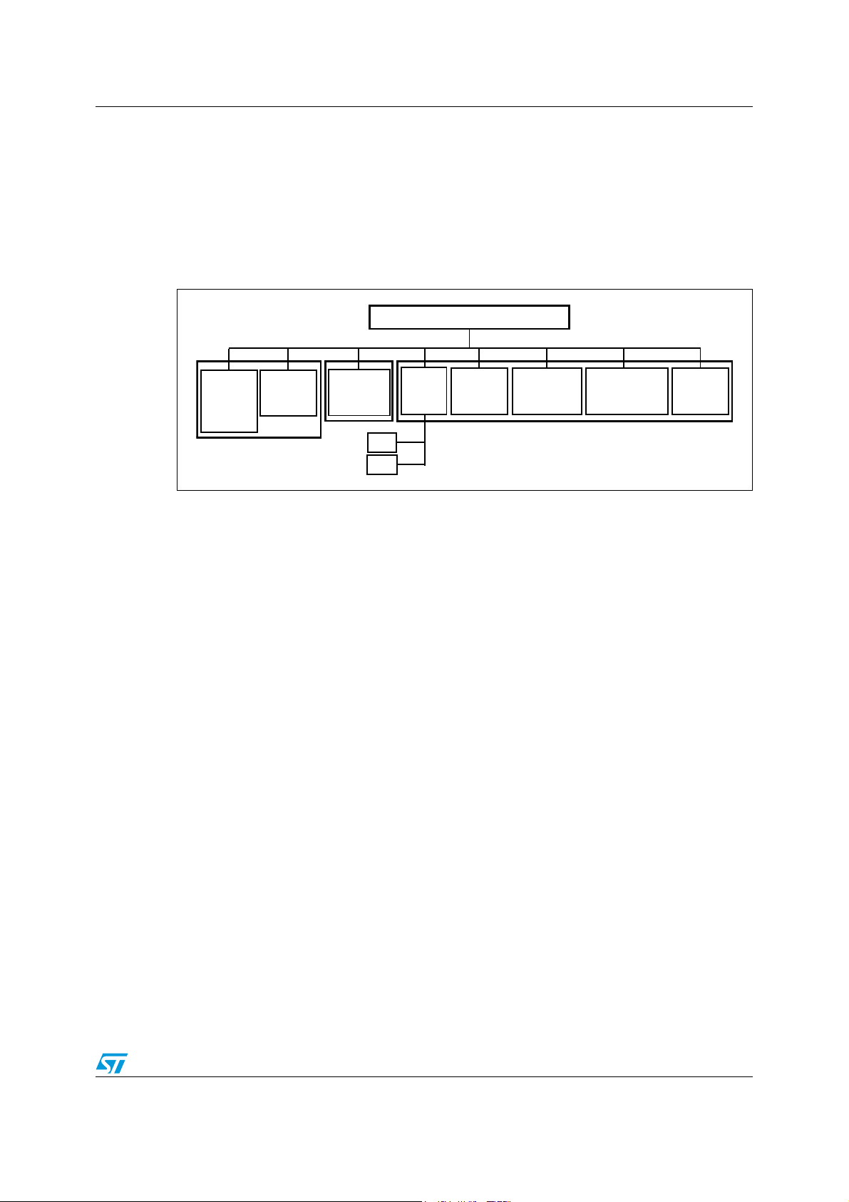
1 Functions set overview
The SPI_FS is a set of functions included in ST10 electric motor control library (see
Figure 1). It uses the ST10 peripheral SSC configured like SPI interface to allow the full
duplex communication with MP49 (slave) and to set a specific MP49 parameters
configuration or diagnosis requests, see Tabl e 2.
Figure 1. ST10 EMC library structure
ST10 EMCL
Flux
Oriented
Control
Sinusoidal
Control
Observer
Leunberger
spi.c
spi.h
SPI
Driver
Encoder
Driver
Hall sensors
Driver
Current sensing
Driver
PWM
Driver
The communication between the CPU board and the motor power board is based on SPI
interface with a chip select (4 signals in total).
The exchanged data set some parameters and the command to read the status of the motor
power board. The configuration command allows to choose the shape of fault pin output
signal. Another subset of commands allows to send diagnosis requests to read the status of
the inverter driver and of the powerMOS.
5/18
Page 6
MP49 to CPU board communication overview AN2500
2 MP49 to CPU board communication overview
The MP49 motor power board communicates with the CPU board using an SPI interface
and using a fault signal to report to the CPU faults as soon as they are detected.
The MP49 requires only to be configured after reset and the CPU does not need any action
after initialization as long as the fault pin is not active.
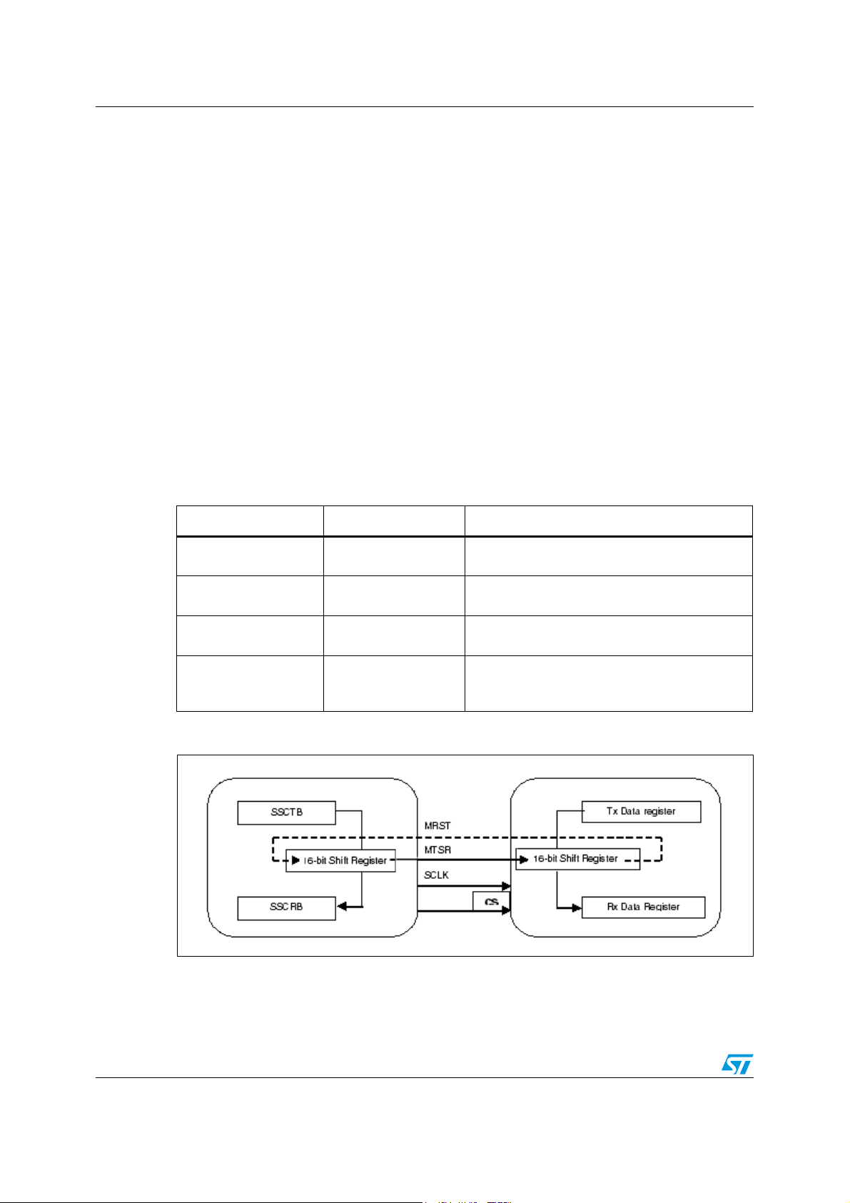
2.1 SPI interface
The SPI interface provides a full-duplex, synchronous serial communication between
microcontrollers and peripherals. It is based upon a Master-Slave protocol where the master
is the device that drives the serial clock signal (SCLK), used to synchronize the
communication.
The SPI bus consists of four wires, Serial Clock signal (SCLK), Master Transmit / Slave
Receive (MTSR), Master Receive / Slave Transmit (MRST), and Chip Select (CS), which
carry information between the devices connected to the bus (see Figure 2).
Table 1. SPI master signal description
Name Direction Description
MTSR Output
MRST Input
SCLK Output
CS Output
Figure 2. SPI registers
SPI Serial Data Output. Serial data output from
the SPI Master to a SPI slave.
SPI Serial Data Input. Serial data input from a
SPI slave to the SPI Master.
SPI Serial Clock. Normally high, and the correct
clock pulse number is sixteen.
SPI Slave Selects. Normally high, this input
signal starts the communication when it is forced
low (for selecting the MP49 board use pin P2.7).
The SCLK control line is driven by the SPI Master and regulates the flow of data bits, so that
data is shifted on falling edge of SCLK and is sampled on the opposite edge when the data
is stable.
6/18
Page 7

AN2500 MP49 to CPU board communication overview
This input signal to the MP49 is normally high and the correct clock pulse number is sixteen
with a maximum clock frequency of 4MHz. The master may transmit data at a variety of
baud rates.
Note: SPI messages shall be separated by a wait time of 5us minimum. This shall be guaranteed
by CPU software.
2.2 SPI diagnostic
The MP49 circuitry includes SPI diagnostic circuitry. The CPU must follow the commands
defined in the library. In case of improper command, a fault reporting a SPI diagnostic will be
generated.
2.2.1 Fault detection interface
The fault pin from the MP49 board is activated (low level) as soon as at least 1 fault
condition occurs.
The CPU then can use status read commands to read the status registers to diagnose the
system.
The fault pin is released after the CPU has read the register showing the fault and when
there is no more fault condition (continuous hardware detection).
The detected faults are Motor Pre-Driver diagnosis, Thermal Detection, PowerMOS short
circuit, Current Regulator diagnosis, LCHG pin diagnosis and SPI communication diagnosis.
When there is no fault, the signal on the fault pin can be configured to be a static high signal
or to be a 4ms period signal (pulses).
By default, the fault pin is set to be a 4ms pulse signal (see Figure 3).
Figure 3. Fault signal
Fault condition
Fault s ign al
Fault ou tp ut (normal mode)
Fault output (pulse m ode)
4m s
7/18
Page 8

API specification AN2500
3 API specification
The following APIs allow easy access to set a specific configuration or read the status of the
motor power board.
The use of these functions eliminates the need to access directly ST10 registers.
Available functions:
● SetCom()
● ShortMotorDriver()
● LowVoltPreDriver()
● SPINGFailDetect()
described in the following.
The communication between the ST10 microcontroller and the MP49 power board through
the SPI interface uses a set of four commands, listed in Tabl e 2 , to set a specific MP49
parameters configuration or a diagnosis request.
Table 2. SPI commands
Item Definition
COMMAND configuration of a parameters set
DIAG_READ1 Motor Driver Short Diagnosis
DIAG_READ2 Pre Driver VGS Low Voltage
DIAG_READ3 SPI Diagnosis
The command to set the MP49 board configuration sends back the echo of the
configuration. Note that when the diagnosis requests are read from the microcontroller, each
flag of the Tx data register from MP49 board is cleared.
In the following the functions that allow to set a specific configuration, read the echo from
MP49 power board, and send a specific diagnosis request are listed
(see file spi.c in the sw library).
8/18
Page 9

AN2500 API specification
3.1 Function definition for motor power board configuration
In the following the function for setting a specific MP49 parameters configuration is specified
(see file spi.c in the sw library).
3.1.1 SetCom
Prototype definition:
UINT16 SetCom( UINT16 command )
Parameters:
Parameter Description
command
Command to set the
Define command value using OR-ing of constants defined in spi.h
MP49 power board.
Return value:
Return value Description / meaning
OK no errors
FAIL_REGWRITE_
FAIL_
MP49 read data is different from sent one
MP49 wrong keyword
Description:
Set the command to MP49 and check the echo from MP49.
Example:
SetCom(COMMAND | PSA_ON | FAULT_OUT_NORMAL)
See predefined constants in spi.h.
9/18
Page 10

API specification AN2500
3.2 Function definitions for the motor power board diagnosis
In the following the functions for the diagnosis are specified, (see file spi.c).
3.2.1 ShortMotorDriver
Prototype definition:
UINT16 ShortMotorDriver( struct DIAG1*p_ diag_1 )
Parameters:
Parameter Description
p_diag_1 pointer to diagnosis structure
Return value:
Return value Description/meaning
OK no short
FAIL _
MP49_DIAG found short
MP49 wrong keyword
FAIL_
Description:
Set the command to MP49 power board and read the status of short diagnosis of the motor
driver.
3.2.2 LowVoltPreDriver
Prototype definition:
UINT16 LowVoltPreDriver( struct DIAG2* p_diag_2 )
Parameters:
Parameter Description
p_diag_2 pointer to diagnosis structure
Return value:
Return value Description/meaning
OK normal
FAIL _
MP49_DIAG found fail
MP49 wrong keyword
FAIL_
Description:
Set the command to MP49 power board and read the status of low voltage diagnosis of the pre-
driver.
10/18
Page 11

AN2500 API specification
3.2.3 SPINGFailDetect
Prototype definition:
UINT16 SPINGFailDetect( struct DIAG3* p_diag_3 )
Parameters:
Parameter Description
p_diag_3 pointer to the diagnosis structure
Return value:
Return value Description/meaning
OK normal
FAIL _MP49_DIAG_SPING found fail
MP49 wrong keyword
FAIL_
Description:
Set the command to MP49 power board and read the status of diagnosis of SPI.
11/18
Page 12

API specification AN2500
3.3 Type definitions
There are three different structures, here defined, to store the status of diagnosis for each
request command, used in functions of diagnosis (e.g. DIAG1 for short diagnosis of the
MOTOR DRIVER).
3.3.1 DIAG1
Table 3. DIAG1 structure
Type: struct
Each field of the structure stores short diagnosis on motor driver:
Description:
3.3.2 DIAG2
Table 4. DIAG2 structure
Type: struct
WL,WH,VL,VH,UL,UH.
See the file spi.h
Description:
3.3.3 DIAG3
Table 5. DIAG3 structure
Type: struct
Description:
Each field of the structure stores low voltage diagnosis on pre driver VGS:
W LV, W HV, V LV, V H V, UL V,U H V.
See the file spi.h.
The structure stores the Fail:
SPING
See the file spi.h.
12/18
Page 13

AN2500
Appendix A
The following table is showing the commands available to configure the MP49 power board.
Configuration command
1514131211109876543 2 10
000001XX00001FAULT00
Name Bits Value Description
Command field 15 to 10
dummy bits 9, 8 x
reserved bit field1 7,6,5,4 0000
reserved bit field2 3 1
must be
“000001”
Command key word
Dummy bits
The value of those bits is ignored.
Reserved
The software must always write those bits as 0
Reserved
The software must always write those bits as 1
FAULT pin signal selection
FAULT 2 0
1
reserved bit field3 1,0 00
pulse mode (default value after reset)
level mode (no-fault = high-level; fault = low-level)
Reserved
The software must always write those bits as 0
Motor driver short diagnosis read command
15 14 13 12 11 10 9 8 7 6 5 4 3 2 1 0
001000
Name Bits Value Description
XXx
xxxxx xx
Read DIAG_READ1 key word
Command field 15 to 10
must be
“001000”
On the next command, the MP49 board will
send the Motor driver short register on the
SPI.
dummy bits 9 to 0 x
Dummy bits
The value of those bits is ignored.
Predriver’s low voltage diagnosis read command
15 14 13 12 11 10 9 8 7 6 5 4 3 2 1 0
010000XXxxxxx x xx
13/18
Page 14

Name Bits Value Description
Read DIAG_READ2 key word
Command field 15 to 10
must be
“010000”
On the next command, the MP49 board will
send the Predriver’s low voltage register on the
SPI.
AN2500
dummy bits 9 to 0 x
Dummy bits
The value of those bits is ignored.
SPI communication diagnosis read command
15 14 13 12 11 10 9 8 7 6 5 4 3 2 1 0
011000XXxxxxx x xx
Name Bits Value Description
Read DIAG_READ3 key word
Command field 15 to 10
must be
“011000”
On the next command, the MP49 board will
send the SPI communication register on the
SPI.
dummy bits 9 to 0 x
Dummy bits
The value of those bits is ignored.
The following table is showing the meaning of the status registers of the MP49 power board.
Motor driver short diagnostic
15 14 13 12 11 10 9 8 7 6 5 4 3 2 1 0
x001000xUHULVHVLWHWL00
Name Bits Value Description
Command echo field 14 to 9 001000
UH 7
UL 6
VH 5
14/18
Read DIAG_READ1 command key word
this bit field is echoing the command field of
the read DIAG_READ1 command
PowerMOS UH short diagnostic
0 = normal
1 = short
PowerMOS UL short diagnostic
0 = normal
1 = short
PowerMOS VH short diagnostic
0 = normal
1 = short
Page 15

AN2500
Name Bits Value Description
PowerMOS VL short diagnostic
VL 4
0 = normal
1 = short
PowerMOS WH short diagnostic
WH 3
0 = normal
1 = short
PowerMOS WL short diagnostic
WL 2
0 = normal
1 = short
dummy bits 1,0
Reserved
Those bits are always 0.
PREdriver low voltage diagnostic
15 14 13 12 11 10 9 8 7 6 5 4 3 2 1 0
x011000xUHVULVVHVVLVWHVWLV00
Name Bits Value Description
Command echo field 14 to 9 010000
UHV 7
ULV 6
VHV 5
VLV 4
WHV 3
WLV 2
dummy bits 1,0
Read DIAG_READ2 command key word
this bit field is echoing the command field of
the read DIAG_READ2 command
UHV predriver short diagnostic
0 = normal
1 = under voltage
ULV short diagnostic
0 = normal
1 = under voltage
VHV short diagnostic
0 = normal
1 = under voltage
VLV short diagnostic
0 = normal
1 = under voltage
WHV short diagnostic
0 = normal
1 = under voltage
WLV short diagnostic
0 = normal
1 = under voltage
Reserved
Those bits are always 0.
15/18
Page 16

AN2500
SPI communication diagnostic
15 14 13 12 11 10 9 8 7 6 5 4 3 2 1 0
x011000xxxSPINGxx x x0
Name Bits Value Description
Read DIAG_READ3 command key word
Command echo field 14 to 9 011000
dummy bits 8,7,6
SPING 5
this bit field is echoing the command field of
the read status3 command
Reserved
Those bits should be ignored (either 0 or 1).
SPI diagnostic
0 = normal
1 = SPI error (non valid command in
command bit field or less than 16 clock
periods in an SPI frame.
dummy bits 4,3,2,1
dummy bits 0
Reserved
Those bits should be ignored (either 0 or 1).
Reserved
This bit is always 0.
16/18
Page 17

AN2500 Revision history
4 Revision history
Table 6. Document revision history
Date Revision Changes
09-Mar-2007 1 Initial release.
17/18
Page 18

AN2500
Please Read Carefully:
Information in this document is provided solely in connection with ST products. STMicroelectronics NV and its subsidiaries (“ST”) reserve the
right to make changes, corrections, modifications or improvements, to this document, and the products and services described herein at any
time, without notice.
All ST products are sold pursuant to ST’s terms and conditions of sale.
Purchasers are solely responsible for the choice, selection and use of the ST products and services described herein, and ST assumes no
liability whatsoever relating to the choice, selection or use of the ST products and services described herein.
No license, express or implied, by estoppel or otherwise, to any intellectual property rights is granted under this document. If any part of this
document refers to any third party products or services it shall not be deemed a license grant by ST for the use of such third party products
or services, or any intellectual property contained therein or considered as a warranty covering the use in any manner whatsoever of such
third party products or services or any intellectual property contained therein.
UNLESS OTHERWISE SET FORTH IN ST’S TERMS AND CONDITIONS OF SALE ST DISCLAIMS ANY EXPRESS OR IMPLIED
WARRANTY WITH RESPECT TO THE USE AND/OR SALE OF ST PRODUCTS INCLUDING WITHOUT LIMITATION IMPLIED
WARRANTIES OF MERCHANTABILITY, FITNESS FOR A PARTICULAR PURPOSE (AND THEIR EQUIVALENTS UNDER THE LAWS
OF ANY JURISDICTION), OR INFRINGEMENT OF ANY PATENT, COPYRIGHT OR OTHER INTELLECTUAL PROPERTY RIGHT.
UNLESS EXPRESSLY APPROVED IN WRITING BY AN AUTHORIZED ST REPRESENTATIVE, ST PRODUCTS ARE NOT
RECOMMENDED, AUTHORIZED OR WARRANTED FOR USE IN MILITARY, AIR CRAFT, SPACE, LIFE SAVING, OR LIFE SUSTAINING
APPLICATIONS, NOR IN PRODUCTS OR SYSTEMS WHERE FAILURE OR MALFUNCTION MAY RESULT IN PERSONAL INJURY,
DEATH, OR SEVERE PROPERTY OR ENVIRONMENTAL DAMAGE. ST PRODUCTS WHICH ARE NOT SPECIFIED AS "AUTOMOTIVE
GRADE" MAY ONLY BE USED IN AUTOMOTIVE APPLICATIONS AT USER’S OWN RISK.
Resale of ST products with provisions different from the statements and/or technical features set forth in this document shall immediately void
any warranty granted by ST for the ST product or service described herein and shall not create or extend in any manner whatsoever, any
liability of ST.
ST and the ST logo are trademarks or registered trademarks of ST in various countries.
Information in this document supersedes and replaces all information previously supplied.
The ST logo is a registered trademark of STMicroelectronics. All other names are the property of their respective owners.
© 2007 STMicroelectronics - All rights reserved
STMicroelectronics group of companies
Australia - Belgium - Brazil - Canada - China - Czech Republic - Finland - France - Germany - Hong Kong - India - Israel - Italy - Japan -
Malaysia - Malta - Morocco - Singapore - Spain - Sweden - Switzerland - United Kingdom - United States of America
www.st.com
18/18
 Loading...