

Page 1

AN2326
Obsolete Product(s) - Obsolete Product(s) Obsolete Product(s) - Obsolete Product(s)
Application note
Calibrating the RC oscillator of the
ST7ULTRALITE MCU using the mains
Introduction
The ST7ULTRALITE microcontroller contains an internal RC oscillator which can be
trimmed to a specific frequency with the required accuracy. The oscillator frequency has to
be calibrated by software using the RCCR register (RC Control Register) and the SICSR
register (System Integrity Control/Status Register). The value entered in the RCCR/SICSR
registers will switch ON a corresponding number of resistors that will modify the oscillator
frequency. Whenever the ST7ULTRALITE microcontroller is reset, the 10-bit value
contained in the RCCR/SICSR registers is restored to its default value (3FFh) i.e. the lower
possible frequency, so each time the device is reset, you have to load the calibration value in
the RCCR/SICSR registers. There are predefined calibration values stored in memory (refer
to the” Internal RC Oscillator Adjustment” section in the ST7ULTRALITE datasheet). You
can load one of these values in the RCCR/SICSR registers if one of the operating conditions
matches that in your application. Otherwise, you can define your own value, store it in non
volatile memory and load it in the RCCR/SICSR registers after each reset. However, if any
of the external conditions (temperature or voltage, for instance) changes too drastically, the
stored value may no longer produce the required accuracy. One solution is to recalculate the
RCCR/SICSR register values after each reset, based on an external reference.
The purpose of this application note is to present a software solution using the frequency of
the European standard mains (220V/50Hz) as a timebase to adjust the internal RC oscillator
of the ST7ULTRALITE to 8 MHz. The same approach can also be used for the US mains
standard (110V/60Hz).
The basic software takes less than 200 ms to calibrate the oscillator and uses less than128
bytes of program memory and five bytes of RAM for its simplest version. These RAM bytes
can be freed for other purposes when the calibration is done. Another example using
averages is given in this application note. This can be useful with noisy mains.
This application note also contains the diagram of a low cost circuit which converts the
mains into a 5 volt power supply and protects the microcontroller from overcurrent on the
input connected to the mains.
April 2006 Rev 1 1/20
www.st.com
Page 2

Obsolete Product(s) - Obsolete Product(s) Obsolete Product(s) - Obsolete Product(s)
Contents AN2326
Contents
1 Calibration software . . . . . . . . . . . . . . . . . . . . . . . . . . . . . . . . . . . . . . . . . 3
1.1 Software principle . . . . . . . . . . . . . . . . . . . . . . . . . . . . . . . . . . . . . . . . . . . . 3
1.2 Basic version . . . . . . . . . . . . . . . . . . . . . . . . . . . . . . . . . . . . . . . . . . . . . . . 4
1.3 Average version . . . . . . . . . . . . . . . . . . . . . . . . . . . . . . . . . . . . . . . . . . . . . 5
2 Power supply and timebase delivery circuit . . . . . . . . . . . . . . . . . . . . . . 7
2.1 Basic circuit . . . . . . . . . . . . . . . . . . . . . . . . . . . . . . . . . . . . . . . . . . . . . . . . 7
2.2 Hardware protection . . . . . . . . . . . . . . . . . . . . . . . . . . . . . . . . . . . . . . . . . . 8
3 Conclusion . . . . . . . . . . . . . . . . . . . . . . . . . . . . . . . . . . . . . . . . . . . . . . . . . 9
4 Software examples . . . . . . . . . . . . . . . . . . . . . . . . . . . . . . . . . . . . . . . . . 10
4.1 Single alternance . . . . . . . . . . . . . . . . . . . . . . . . . . . . . . . . . . . . . . . . . . . 10
4.1.1 Main program . . . . . . . . . . . . . . . . . . . . . . . . . . . . . . . . . . . . . . . . . . . . . 10
4.1.2 Input capture interrupt . . . . . . . . . . . . . . . . . . . . . . . . . . . . . . . . . . . . . . 11
4.1.3 Timebase interrupt . . . . . . . . . . . . . . . . . . . . . . . . . . . . . . . . . . . . . . . . . 12
4.1.4 Writing in non volatile memory for products without Data EEPROM . . . 12
4.1.5 Writing in non volatile memory for products with Data EEPROM . . . . . 13
4.1.6 Detailed basic version software flowchart . . . . . . . . . . . . . . . . . . . . . . . 14
4.2 Average version . . . . . . . . . . . . . . . . . . . . . . . . . . . . . . . . . . . . . . . . . . . . 15
4.2.1 Main program . . . . . . . . . . . . . . . . . . . . . . . . . . . . . . . . . . . . . . . . . . . . . 15
4.2.2 Input capture interrupt . . . . . . . . . . . . . . . . . . . . . . . . . . . . . . . . . . . . . . 16
4.2.3 Timebase interrupt . . . . . . . . . . . . . . . . . . . . . . . . . . . . . . . . . . . . . . . . . 17
5 Revision history . . . . . . . . . . . . . . . . . . . . . . . . . . . . . . . . . . . . . . . . . . . 19
2/20
Page 3
Obsolete Product(s) - Obsolete Product(s) Obsolete Product(s) - Obsolete Product(s)
AN2326 Calibration software
1 Calibration software
1.1 Software principle
The software algorithm, described in the following flowchart (see Figure 3.), uses the mains
frequency as a timebase. This timebase allows the microcontroller to test if the RC oscillator
frequency is above or below the targeted frequency and repeatedly transforms it by
dichotomous analysis so that in 10 iterations the RCCR/SICSR registers are set to the
optimum value. In order to simplify the calculation, the calibration is done at 1MHz, the
8MHz internal RC is divided by 8 thanks to the AVTCHR register.
As the timer speed depends on the RC oscillator frequency, it is easy to determine if the
oscillator is too fast or too slow. The counted value can be obtained by the following
equation:
f
cpu
countedvalue
Since the frequency of the counter is the frequency of the oscillator divided by 32 (only the 8
MSbits are saved on the 13 bits of the counter), if the oscillator is at 1 MHz, the result of the
count between two edges (which have a 10 ms interval), is 138h for the European standard
(220V/50Hz). For the US standard (110V/60Hz) the right value is 104h. Since the goal of the
software is to set the RC oscillator frequency to 1 MHz it means obtaining 138h as the result
of the count. So if the result of the count is greater than 138h, it means that the frequency is
too high so the program increases the value of RCCR/SICSR registers in order to decrease
the RC oscillator frequency. And if the result is less than 138h, the RCCR/SICSR register
value is decreased in order to increase the RC oscillator frequency.
----------------------------=
32 f
×
mains
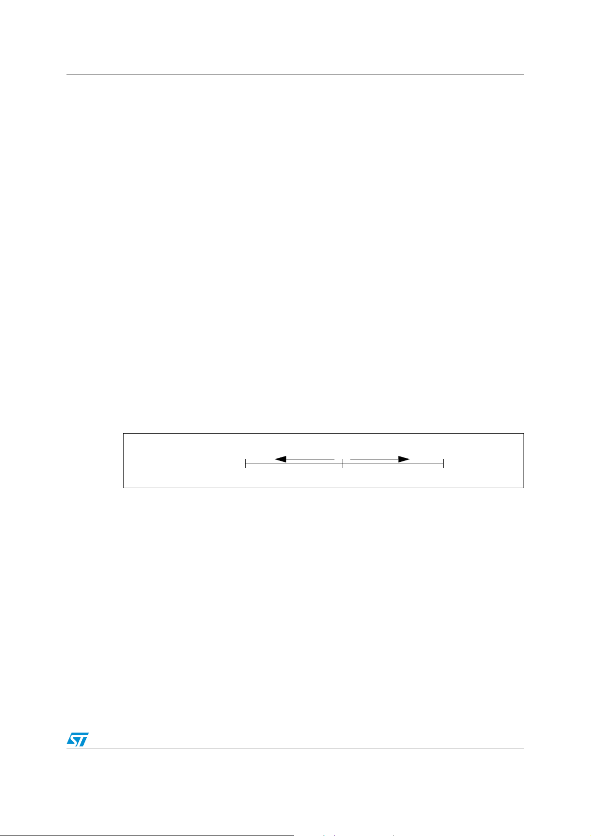
Figure 1. Dichotomous analysis of RCCR value
increase oscillator
frequency
RCCR Register
The RCCR register is set to 80h initially by the program, then the dichotomization starts by
adding or subtracting 40h and after each iteration the result is divided by two, so that after
10 iterations the value of RCCR is set with an accuracy of one bit.
decrease oscillator
frequency
80h
Start Value
FFh0h
3/20
Page 4
Obsolete Product(s) - Obsolete Product(s) Obsolete Product(s) - Obsolete Product(s)
Calibration software AN2326
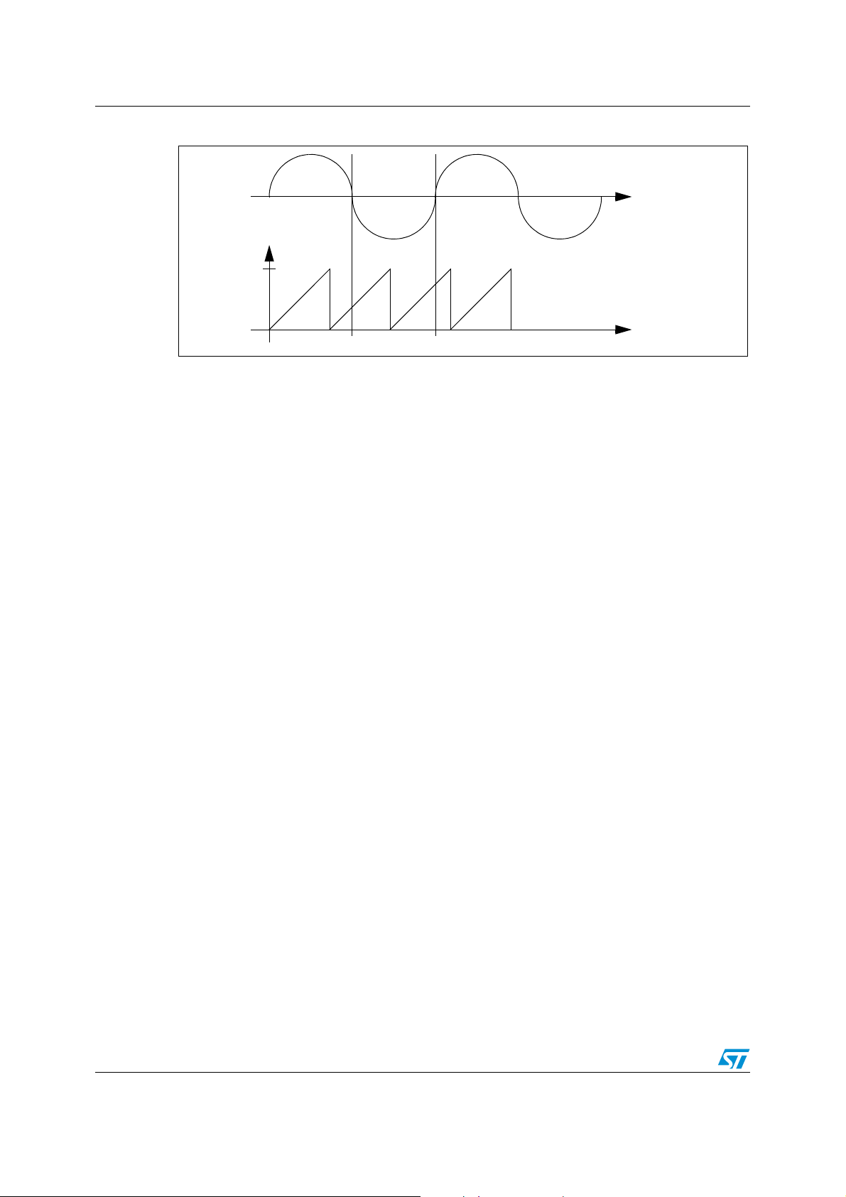
Figure 2. Using the timer input capture to measure the mains frequency
Mains
F9h
0h
To measure the frequency, the software uses the Lite Timer input capture (LTIC) so that on
each edge of the mains the value of the free running counter is stored as shown in Figure 2..
Then the microcontroller calculates the elapsed time between the two edges of the mains.
This time is given by the following equation:
where nbover represents the number of counter overflows during the measurement, capture
1 and capture 2 are the values captured on the free running counter when an edge occurs
on the mains and F9h is the overflow value of the free running counter.
If the RC oscillator frequency is equal to 1 MHz, the result time will be 138h for European
standard (220V/50Hz) or 104h for US standard mains (110V/60Hz), so these are the
reference values.
This measurement result is compared to the reference value and, depending on the result of
the comparison, the microcontroller adds to or subtracts from the current RCCR/SICSR
register values.
Overflow
Free-running
Counter
Capture 1 Capture 2
time nbover F9h capture2 capture1–+×=
1.2 Basic version
In this version the measurement is done only once for each dichotomization step. This
allows the calibration software to be light and fast. It requires only 128 bytes of program
memory and 5 bytes of RAM during calibration. The calibration takes less than 200 ms to be
completed.
The software works as shown in the following flowchart. The assembly code and a more
detailed flowchart can be found in Section 4.
4/20
Page 5
Obsolete Product(s) - Obsolete Product(s) Obsolete Product(s) - Obsolete Product(s)
AN2326 Calibration software
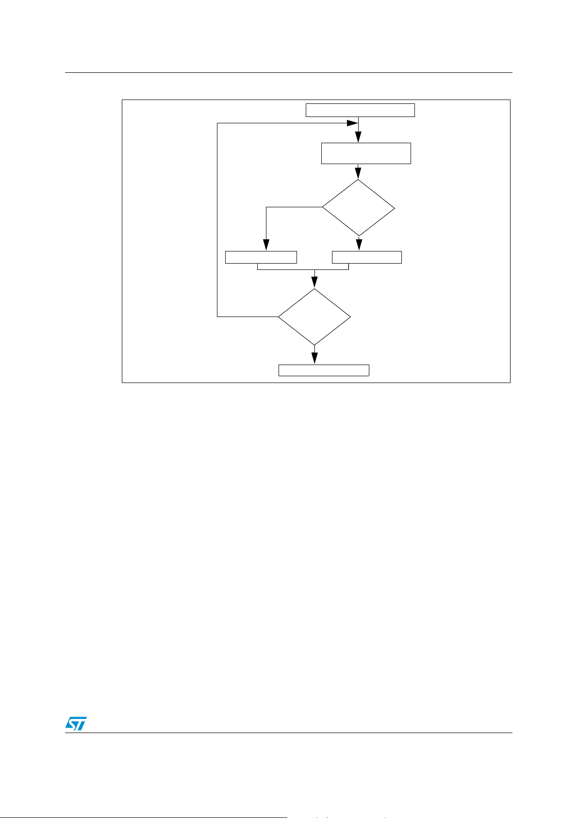
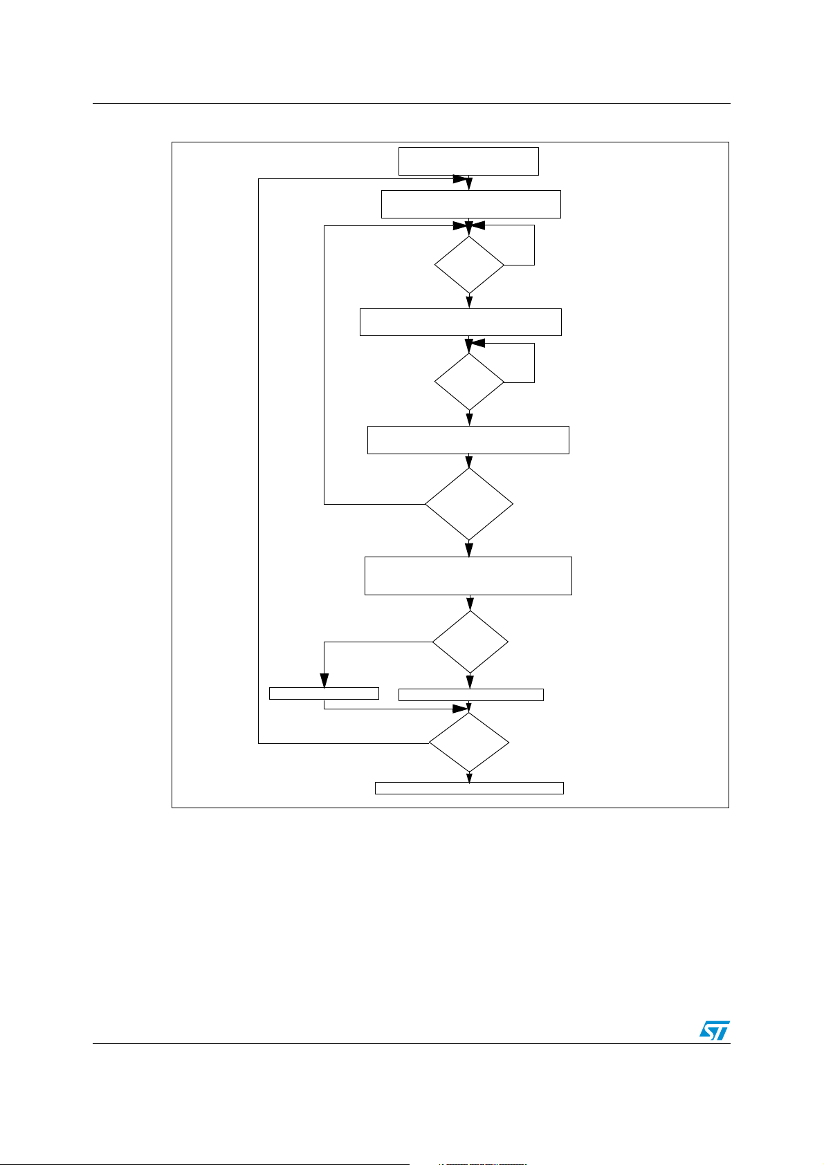
Figure 3. Basic software flowchart
Initialization of Lite Timer
Measurement and
calculation
1.3 Average version
This version uses the method described in Section 1.1 except it performs four measurements and uses
their average for each dichotomization step. It is useful when the mains is noisy. For instance, when a
motor starts it generates a tension pick and this can be considered as a mains edge.
This version is safer than the basic one but it requires more resources. It uses 136 bytes of program
memory and 11 bytes of RAM during calibration. The calibration takes less than 800 ms to be completed.
The average version works as shown in the following flowchart. The assembly code can be found in
Section 4.
smaller
no
Dichotomization
finished?
yes
Clock is set to 1 MHz
Compare
result with
reference
greater or equal
Increase RCCRDecrease RCCR
5/20
Page 6
Obsolete Product(s) - Obsolete Product(s) Obsolete Product(s) - Obsolete Product(s)
Calibration software AN2326
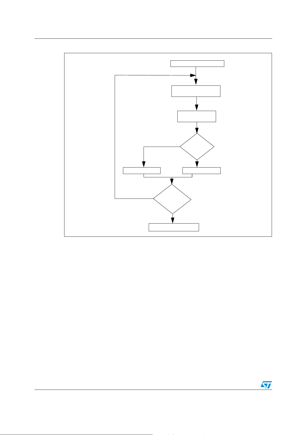
Figure 4. Average software flowchart
Initialization of Lite Timer
4 measurements and
calculation
Average
smaller
Decrease RCCR
no
Clock is set to 1 MHz
Dichotomization
finished?
yes
Compare
result with
reference
greater or equal
Increase RCCR
6/20
Page 7
Obsolete Product(s) - Obsolete Product(s) Obsolete Product(s) - Obsolete Product(s)
AN2326 Power supply and timebase delivery circuit
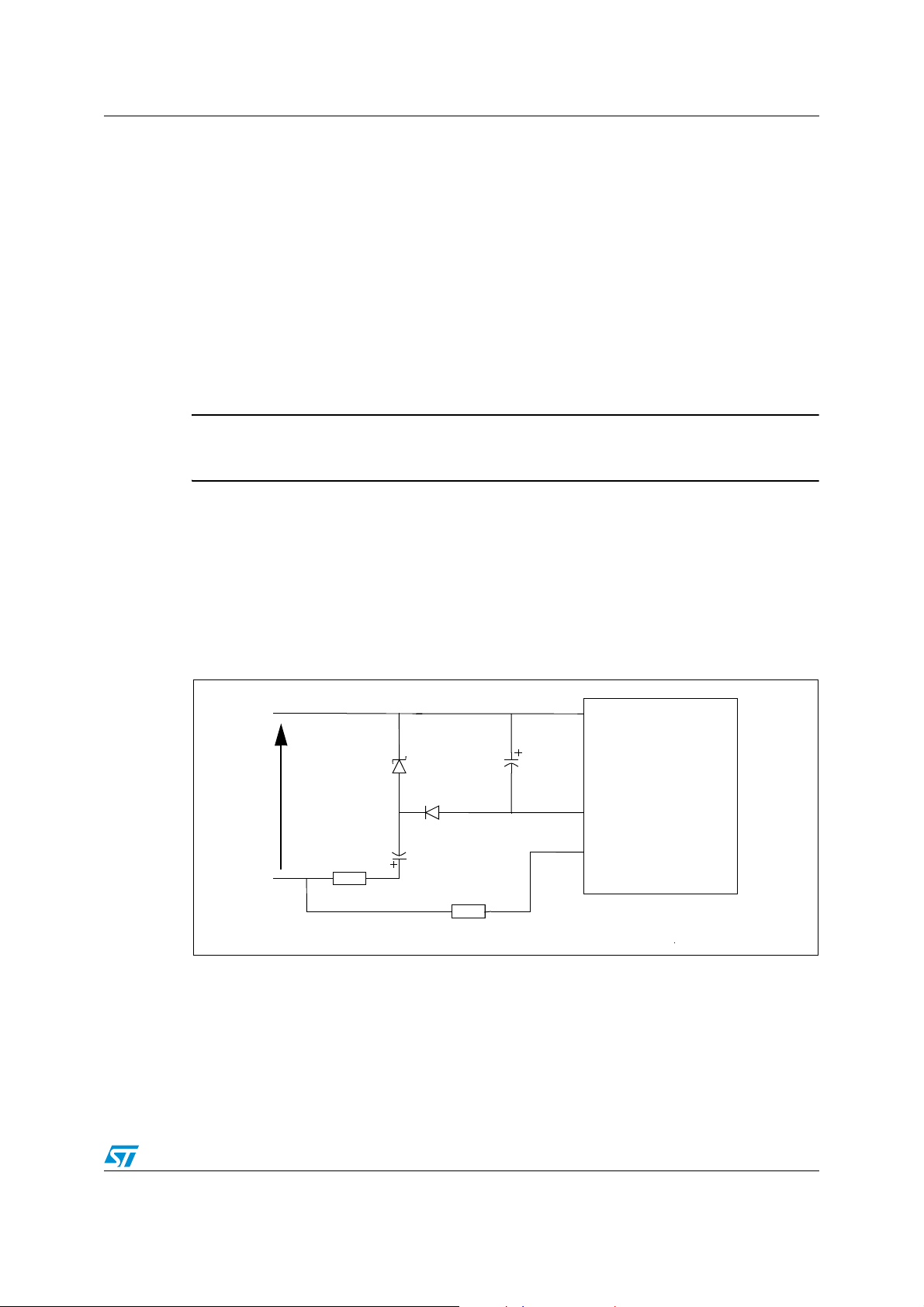
2 Power supply and timebase delivery circuit
The following figures show circuits which will provide 5V DC to the ST7ULTRALITE and
protect the input capture from overcurrent. If no power supply is needed, the only
component to keep is the resistor on the LTIC input, which is mainly to protect from
overcurrent.
2.1 Basic circuit
This circuit contains a capacitive power supply which converts the 220V/50Hz of the mains,
as well as the 110V/60Hz of the US mains, into 5V DC.
Warning: be aware that this kind of power supply cannot be used if there are
big current variations.
It also inputs 220V/50Hz to the Lite Timer Input Capture pin (LTIC/PA2) protected by resistor
R2.
The incoming alternating signal on the LTIC input pin is 220V/50Hz. Because of the
clamping diode on the input of the ST7ULTRALITE, the input signal can be considered as a
0-5V square signal.
Figure 5. Power supply and timebase delivery circuit diagram
V
DD
C1
220µF/16V
ST7ULTRALITE
GND
LTIC
Mains
(220V/50Hz)
R1 47R/0.5W
zener
5.6V
1N4148
C2
C2
220nF/400V
R2 470k/0.5W
The maximum current available in the microcontroller depends on the C2 value. Table 1
gives the maximum average current versus the capacitor value. The average current follows
the equation below:
Imax Vmax 2 f C⋅⋅⋅=
In the case above, C2 is equal to 220nF so the available current is limited to 4.9 mA in the
case of a European mains. To have the same current levels in the case of the US mains
7/20
Page 8

Obsolete Product(s) - Obsolete Product(s) Obsolete Product(s) - Obsolete Product(s)
Power supply and timebase delivery circuit AN2326
(110V/60Hz), C2 must be multiplied by two. A 440nF capacitor will limit the current to 4.9
mA.
For the US standard, R2 must be divided by two in order not to limit the current too much on
the LTIC input. A 220kΩ resistor is enough in this case.
Table 1. Maximum MCU current
Capacitor C2 Maximum Current
220nF 4.9mA
330nF 7.3mA
470nF 10.4mA
680nF 15mA
1µF 22.1mA
2.2 Hardware protection
To prevent bad measurements due to noisy mains, a filter can be added between the mains
and the input capture of the ST7ULTRALITE. The following figure shows one example of a
filter. This filter is a pass band centered on the mains frequency in order to reject all
frequency which could be understood by the microcontroller as a mains edge.
Please note that this is just a second order filter and that this may not be enough if the mains
is really noisy. Any kind of filter can be added on the LTIC.
Figure 6. Band pass filter
mains
C1
470nF/400V
The pass band filter above must be tuned to mains frequency. The value of the resistors for
this filter is given in the table below.
Table 2. Resistor values
resistors 50Hz/220V 60Hz/110V
R1 6.8K/0.5W 5.6K/0.5W
R2 6.8K/0.5W 5.6K/0.5W
R3 470K/0.5W 220K/0.5W
R1 R2
C2
470nF/400V 470nF/250V
R3
C2
LTIC
8/20
Page 9

Obsolete Product(s) - Obsolete Product(s) Obsolete Product(s) - Obsolete Product(s)
AN2326 Conclusion
3 Conclusion
This system allows you to have a power supply for the microcontroller and an auto
adjustable clock set to 1, 2, 4 or 8MHz, selected by prescaler, with the required accuracy
whatever the external conditions.
This solution also offers the advantage of being less expensive than a solution with a
transformer and requires less space.
It requires a small amount of space in program memory (less than 128 bytes) in its smallest
version.
9/20
Page 10

Obsolete Product(s) - Obsolete Product(s) Obsolete Product(s) - Obsolete Product(s)
Software examples AN2326
4 Software examples
A zip file attached to this application note contains the complete software of this calibration
method.
4.1 Single alternance
This version performs only one count between two edges and changes the value of the
RCCR/SICSR registers according to this measurement. This can lead to bad tuning if there
is noise on the reference signal.
4.1.1 Main program
;All the bytes from locations 80h to 85h are used by this software to store values or as control
registers but they can be reused safely after the clock has been set.
;dichotomy value
.value equ $81 ;this byte contains the value which will be added or
subtracted to/from the RCCR last value at the end of each round
;capture values
.capture1 equ $82
.capture2 equ $83 ;these two bytes contain the two values of the counter captured on
the edge of the mains, they are used to calculate the time elapsed between the two edges
;number of overflows
.nbover equ $84 ;this byte contains the number of counter overflows during the
measurement
;control register
.cr equ $85 ;this byte is used as a control register for the measurement. Its
bits allow or not the interrupts and show which step of the count is the current one.
.strtstp equ 1 ;this is set to start the count and reset to stop it
.lsb_RCCR equ 7 ;this bit is set when the first capture has occurred. It allows
the overflows to be counted
;address to program in NVM (optional)
.E2ADDR equ $86
.RAM equ $88
.main
ld A, #$63
ld AVDTHCR, A ; set internal clock to fRC/8 meaning 1MHz targeted
clr SICSR ;
ld A, #$80 ;value containing the value which will be
ld value, A ;add or subs to/from RCCR during the dichotomy
ld RCCR, A ;RCCR is set to the middle of its range of value
clr cr ;clear the byte use as control register for the count
next
clr nbover ;clear the byte containing the number of timer overflow
ld A, LTICR ;clear the ICF bit
count
btjt cr, #strtstp, count; wait for the end of count
rim ;interrupts enable
bset LTCSR,
bset cr,#strtstp ;set the start-stop bit of cr: count can start
clr LTCSR ;lite timer interrupts disable
srl value ;dichotomy value divided by 2
ld A,#$F9 ;these lines calculate this equation:
ld X,nbover ;
mul X,A ;(nbover*$F9)+ capture2 - capture1
add A, capture2 ;
jrnc nocarry ;this equation is calculated with 16 bits
inc X ;
clear the 2 lowest significant bits located in this register
#7 ;enable input capture interrupt
10/20
Page 11

Obsolete Product(s) - Obsolete Product(s) Obsolete Product(s) - Obsolete Product(s)
AN2326 Software examples
nocarry
sub A, capture1 ;MSB are in register X
noneg
cp X, #$01 ;if mains frequency is 50Hz the reference value is $138
compare cp A, #$38 ;value is smaller than the reference the program jump to
plus
plus_lsb
btjt value, #5, p_lsb0
btjt value, #4, end
ld A, value
ld SICSR, A ;add value if counted value is greater than ref
jra next
p_lsb0
minus
btjt cr,#lsb_RCCR,minus_lsb
ld A, RCCR
jra new
minus_lsb
btjt value,#5, m_lsb0
btjt value, #4, clr_lsb0
bres RCCR,#0 ;reset the LSb of RCCRH
ld A, value
ld SICSR, A ;substract value if counted value is smaller tha n ref
jra next
m_lsb0
clr_lsb0
new
bset cr, #lsb_RCCR
ld A, #$80
ld value, A
jra next
.end_calibration ; end of the calibration
; at this point the Fcpu is set to 1MHz
; the last operation is to set the clock to the targeted value by setting the prescaler register
jrnc noneg ;
dec X ;and LSB in register A.
jrmi minus ;if it is 60Hz the reference is $104.the program first
jreq compare ;compares MSB with $01 and then compare LSB with
jp plus ;$38 for 50Hz and $04 for 60Hz. if the calculated
jrmi minus ;minus to decrease RCCR else it increase RCCR
btjt cr,#lsb_RCCR,plus_lsb
ld A, RCCR
add A, value ;add value if counted value is greater than ref
jra new
bset SICSR,#5 ;add value if counted value is greater than ref
jra next
sub A, value ;subtract value if Y
bres SICSR,#6
bset SICSR,#5 ;subtract value if Y is smaller
jra next
bres SICSR,#5 ;reset the LSb of RCCRL
jra end
ld RCCR,A ;enter the new value in RCCR
btjf value, #0,
ld A, #$03 ; set clock to fRC meaning 8MHz
; ld A, #$23 ; set prescaler to fRC/2
; ld A, #$43 ; set prescaler
; ld A, #$63 ; set prescaler to fRC/8
ld AVDTHCR,A ; in the three cases AVD is set off
next;stop after 7 rounds
is smaller
to fRC/4
4.1.2 Input capture interrupt
ld A, LTICR ;load captured value in A
btjt LTCSR, #4, finish ;test if it is first or second capture
overflows
finish ld capture2, A ;if it is the second capture, captured value is stored in
capture2
bset LTCSR, #4 ;allow timebase interrupt in order to count the number of
ld capture1, A ;captured value is stored in capture1
jp endit1
clr cr ;clear cr to end the count
11/20
Page 12

Obsolete Product(s) - Obsolete Product(s) Obsolete Product(s) - Obsolete Product(s)
Software examples AN2326
endit1
iret
4.1.3 Timebase interrupt
ld A, LTCSR ;clear TB bit
endit2
inc nbover ;increment number of overflows
iret
4.1.4 Writing in non volatile memory for products without Data EEPROM
To store the final value of RCCR/SICSR registers in non volatile memory, the following lines must be
added after the timer interrupts have been disabled in the main program. As Data EEPROM is not embedded in the ST7ULTRALITE, the storage is done in program memory, so the sector 0 size must be
0.5k (selected by option byte). The programmation routine must be executed from RAM, so it is first
loaded in RAM and then called. Both RCCR and SICSR registers are saved.
; Content of RCCR and SICSR is saved at FC00h and FC01h
; < RESET_FCSR >
LD A,#$56 ; Enter RASS keys to unlock FCSR register
LD FCSR,A
LD A,#$AE
LD FCSR,A
; < LOAD_RAM >
LD X,#$3F ; Copy programming software driver 32 bytes = 4 lines
.RAM_Copy
LD A,(RAM_Driver,X)
LD (RAM,X),A
DEC X
JRPL RAM_Copy
; < USER_APPLICATION_PROGRAM >
; < FIRST_PROG >
LD A,#$FC ; High address
LD X,A ;
clr Y ; define FC00 as destination address
LD {E2ADDR},X ; Address high to be programmed (0081h) is in X
LD {E2ADDR+1},Y ; Address low to be programmed (0082h) is in Y
CALL RAM ; Call the programming driver located into RAM
JP USER_APPLICATION
; ----------------------------------------------------------------------------; ROUTINE: XemulE2_ByteProg
; DESCRIPTION: Emulated data EEPROM byte
; BEFORE: A = data to be programmmed
; X:Y = address where it has to be programmed [FC00h..FDFFh]
; -----------------------------------------------------------------------------
; into RAM from address 0083h
programming driver routine
.RAM_Driver
BSET FCSR,#LAT ; Enable Emul. EEPROM latches
LD A,FCSR
CLR X
LD A, RCCR
LD ([E2ADDR.w],X),A; Set address/data to be programmed
inc X
A, SICSR
LD
LD ([E2ADDR.w],X),A; Set address/data to be programmed
BSET FCSR,#PGM ; Launch the Emul. EEPROM programming
12/20
Page 13

Obsolete Product(s) - Obsolete Product(s) Obsolete Product(s) - Obsolete Product(s)
AN2326 Software examples
.EEPROM_Prog
BTJT FCSR,#PGM,EEPROM_Prog; Wait end of programming (~5ms)
RET
4.1.5 Writing in non volatile memory for products with Data EEPROM
To store final value of RCCR/SICSR registers in EEPROM, add theses lines after disabling the timer interrupts in the main program.
ld RCCR, A
bset EECSR,#1 ;start to enter value in the EEPROM
ld $1003,A ;load value of the RCCR in EEPROM
ld A, SICSR
ld $1004,A ;load value of the SICSR in EEPROM
wait btjt EECSR,#0,wait ;wait for the end of writing in EEPROM
bset EECSR,#0 ;start to write in the EEPROM
13/20
Page 14

Obsolete Product(s) - Obsolete Product(s) Obsolete Product(s) - Obsolete Product(s)
Software examples AN2326
4.1.6 Detailed basic version software flowchart
STORE STARTING VALUE
80H --> VALUE
80H --> RCCR
CLEAR RAM BYTES
ENABLE INPUT CAPTURE INTERRUPT
(NBOVER, CR)
EDGE
ON LTIC
INPUT
YES
STORE CAPTURED VALUE IN CAPTURE 1
ENABLE TIMEBASE INTERRUPT TO
START TO COUNT TIMER OVERFLOWS
EDGE
EDGE
ON LTIC
ON LTIC
INPUT
INPUT
STORE CAPTURED VALUE IN CAPTURE 2
DISABLE TIMEBASE AND INPUT CAPTURE
NBOVER X F9 + CAPTURE 2 - CAPTURE 1
GREATER
SUBTRACT VALUE TO RCCRADD VALUE TO RCCR
YES
INTERRUPTS
DIVIDE VALUE BY 2
CALCULATION OF:
COMPARE
RESULT WITH
138H
SMALLER
NO
NO
NO
RC OSCILLATOR IS TRIMMED TO 1 MHZ
IS THE
DICHOTOMY
FINISHED?
YES
14/20
Page 15

Obsolete Product(s) - Obsolete Product(s) Obsolete Product(s) - Obsolete Product(s)
AN2326 Software examples
4.2 Average version
This version performs the count between two edges four times and changes the value of the
RCCR/SICSR registers according to the average of these measurements. This method
allows to perform a better tune of the RC oscillator especially in noisy environment.
4.2.1 Main program
;All the bytes from locations 80h to 8Bh are used by this software to store values or as control
registers but they can be reused safely after the clock has been set.
;dichotomy value
.value equ $81 ;this byte contains the value which will be added or
subtracted to/from the RCCR last value at the end of each round
;capture values
.capture1 equ $82
.capture2 equ $86 ;these bytes contain the values of the counter captured on the
edge of the mains, they are used to calculate the time elapsed between the two edges
;number of overflows
.nbover equ $8A ;this byte contains the number of counter overflows during the
measurement
;control
.cr equ $8B ;this byte is used as a control register for the measurement. Its
bits allow or not the interrupts and show which step of the count is the current one.
.strtstp equ 1 ;this is set to start the count and reset to stop it
.lsb_RCCR equ 7 ;this bit is set when the first capture has occurred. It allows
the overflows to be counted
;address to program in NVM (optional)
.E2ADDR equ $86
.RAM equ $88
.main
next
clr nbover ;clear the byte containing the number of timer overflow
ld A, LTICR ;clear the ICF bit
capture
rim ;interrupts enable
count
calcul
add A, (capture2,Y) ;
nocarry
sub A, (capture1,Y) ;MSB are in register X
noneg inc Y
register
ld A, #$63
ld AVDTHCR, A ; set internal clock to fRC/8 meaning 1MHz targeted
ld A, #$80 ;value containing the value which will
ld value, A ;add or subs to/from RCCR during the dichotomy
ld RCCR, A ;RCCR is set to the middle of its range of value
clr cr ;clear the byte use as control register for the count
clr Y
bset LTCSR, #7 ;enable input capture interrupt
bset cr,#strtstp ;set the start-stop bit of cr: count can start
btjt cr, #strtstp, count; wait for the end of count
clr LTCSR ;lite timer interrupts disable
inc Y
cp Y,#4 ;repeat the capture four time to make an average
jrne capture
srl value ;dichotomy value divided by 2
clr Y
ld A,#$F9 ;these lines calculate this equation for the four
ld X,nbover;measures:
mul X,A ;(nbover*$F9)+ capture2 - capture1
jrnc nocarry ;this equation is calculated with 16 bits
inc X ;
jrnc noneg ;
dec X ;and LSB in register A.
cp Y,#4
be
15/20
Page 16

Obsolete Product(s) - Obsolete Product(s) Obsolete Product(s) - Obsolete Product(s)
Software examples AN2326
jrne calcul
srl A ;these lines calculate the average of the last four
srl X ;measures by dividing their total by 4. It is done by
jrnc carry1 ;two consecutive right shift on the 16 bit result.
carry1
srl A
carry2
cp X, #$01 ;if mains frequency is 50Hz the reference value is $138
compare
cp A, #$38 ;value is smaller than the reference the program jump to
plus
plus_lsb
btjt value, #5, p_lsb0
btjt value, #4, end
ld A, value
ld SICSR, A ;add value if counted value is greater than ref
jra next
p_lsb0
minus
btjt cr,#lsb_RCCR,minus_lsb
ld A, RCCR
jra new
minus_lsb
btjt value,#5, m_lsb0
btjt value, #4, clr_lsb0
bres RCCR,#0 ;reset the LSb of RCCRH
ld A, value
ld SICSR, A ;substract value if counted value is smaller
jra next
m_lsb0
clr_lsb0
new ld RCCR,A ;enter the new value in RCCR
next_near
.end_calibration ; end of the calibration
; at this point the Fcpu is set to 1MHz
; the last operation is to set the clock to
add A,#$80
srl X
jrnc carry2
add A,#$80
jrmi minus ;if it is 60Hz the reference is $104.the program first
jreq compare;compares MSB with $01 and then compare LSB with
jp plus ;$38 for 50Hz and $04 for 60Hz. if the calculated
jrmi minus ;minus to decrease RCCR else it increase RCCR
btjt cr,#lsb_RCCR,plus_lsb
ld A, RCCR
add A, value ;add value if counted value is greater than ref
jra new
bset SICSR,#5 ;add value if counted value is greater than ref
jra next
sub A, value ;subtract value if Y is smaller
than ref
bres SICSR,#6
bset SICSR,#5 ;subtract value if Y is smaller
jp next
bres SICSR,#5 ;reset the LSb of RCCRL
jra end
btjf value, #0, next_near;stop after 7 rounds
bset cr, #lsb_RCCR
ld A, #$80
ld value, A
jp next
ld A, #$03 ; set clock to fRC meaning 8MHz
; ld A, #$23 ; set prescaler to fRC/2
; ld A, #$43 ; set prescaler to fRC/4
; ld A, #$63 ; set prescaler to fRC/8
ld AVDTHCR,A ; in the three cases AVD is set off
the targeted value by setting the prescaler register
4.2.2 Input capture interrupt
ld A, LTICR ;load captured value in A
btjt LTCSR, #4, finish ;test if it is first or second capture
16/20
Page 17

Obsolete Product(s) - Obsolete Product(s) Obsolete Product(s) - Obsolete Product(s)
AN2326 Software examples
overflows
finish
capture2
endit1 iret
bset LTCSR, #4 ;allow timebase interrupt in order to count the number of
ld (capture1,Y), A ;captured value is stored in capture1
jp endit1
ld (capture2,Y), A ;if it is the second capture, captured value is stored in
clr cr ;clear cr to end the count
4.2.3 Timebase interrupt
ld A, LTCSR ;clear TB bit
endit2
inc nbover ;increment number of overflows
iret
17/20
Page 18
Obsolete Product(s) - Obsolete Product(s) Obsolete Product(s) - Obsolete Product(s)
Software examples AN2326
Table 3. Detailed average version software flowchart
STORE STARTING VALUE
80H --> VALUE
80H --> RCCR
CLEAR RAM BYTES
ENABLE INPUT CAPTURE INTERRUPT
(NBOVER, CR)
EDGE
ON LTIC
INPUT
YES
STORE CAPTURED VALUE IN CAPTURE 1.X
ENABLE TIMEBASE INTERRUPT TO
START TO COUNT TIMER OVERFLOWS
EDGE
ON LTIC
INPUT
STORE CAPTURED VALUE IN CAPTURE 2.X
DISABLE TIMEBASE AND INPUT CAPTURE
NBOVER X F9 + 4(CAPTURE2.X - CAPTURE1.X)
RESULT DIVIDED BY 4 TO AVERAGE IT
EQUAL OR GREATER
YES
INTERRUPTS
FOUR
MEASUREMENTS
DONE?
CALCULATION OF:
DIVIDE VALUE BY 2
COMPARE
RESULT WITH
138H
NO
NO
YES
ADD VALUE TO RCCR
SMALLER
SUBTRACT VALUE TO RCCR
NO
RC OSCILLATOR IS TRIMMED TO 1 MHZ
IS THE
DICHOTOMY
FINISHED?
YES
18/20
Page 19

Obsolete Product(s) - Obsolete Product(s) Obsolete Product(s) - Obsolete Product(s)
AN2326 Revision history
5 Revision history
Table 4. Document revision history
Date Revision Changes
03-April-2006 1 Initial release.
19/20
Page 20

Obsolete Product(s) - Obsolete Product(s) Obsolete Product(s) - Obsolete Product(s)
Revision history AN2326
Please Read Carefully:
Information in this document is provided solely in connection with ST products. STMicroelectronics NV and its subsidiaries (“ST”) reserve the
right to make changes, corrections, modifications or improvements, to this document, and the products and services described herein at any
time, without notice.
All ST products are sold pursuant to ST’s terms and conditions of sale.
Purchasers are solely responsible for the choice, selection and use of the ST products and services described herein, and ST assumes no
liability whatsoever relating to the choice, selection or use of the ST products and services described herein.
No license, express or implied, by estoppel or otherwise, to any intellectual property rights is granted under this document. If any part of this
document refers to any third party products or services it shall not be deemed a license grant by ST for the use of such third party products
or services, or any intellectual property contained therein or considered as a warranty covering the use in any manner whatsoever of such
third party products or services or any intellectual property contained therein.
UNLESS OTHERWISE SET FORTH IN ST’S TERMS AND CONDITIONS OF SALE ST DISCLAIMS ANY EXPRESS OR IMPLIED
WARRANTY WITH RESPECT TO THE USE AND/OR SALE OF ST PRODUCTS INCLUDING WITHOUT LIMITATION IMPLIED
WARRANTIES OF MERCHANTABILITY, FITNESS FOR A PARTICULAR PURPOSE (AND THEIR EQUIVALENTS UNDER THE LAWS
OF ANY JURISDICTION), OR INFRINGEMENT OF ANY PATENT, COPYRIGHT OR OTHER INTELLECTUAL PROPERTY RIGHT.
UNLESS EXPRESSLY APPROVED IN WRITING BY AN AUTHORIZE REPRESENTATIVE OF ST, ST PRODUCTS ARE NOT DESIGNED,
AUTHORIZED OR WARRANTED FOR USE IN MILITARY, AIR CRAFT, SPACE, LIFE SAVING, OR LIFE SUSTAINING APPLICATIONS,
NOR IN PRODUCTS OR SYSTEMS, WHERE FAILURE OR MALFUNCTION MAY RESULT IN PERSONAL INJURY, DEATH, OR
SEVERE PROPERTY OR ENVIRONMENTAL DAMAGE.
Resale of ST products with provisions different from the statements and/or technical features set forth in this document shall immediately void
any warranty granted by ST for the ST product or service described herein and shall not create or extend in any manner whatsoever, any
liability of ST.
ST and the ST logo are trademarks or registered trademarks of ST in various countries.
Information in this document supersedes and replaces all information previously supplied.
The ST logo is a registered trademark of STMicroelectronics. All other names are the property of their respective owners.
© 2006 STMicroelectronics - All rights reserved
STMicroelectronics group of companies
Australia - Belgium - Brazil - Canada - China - Czech Republic - Finland - France - Germany - Hong Kong - India - Israel - Italy - Japan -
Malaysia - Malta - Morocco - Singapore - Spain - Sweden - Switzerland - United Kingdom - United States of America
www.st.com
20/20
 Loading...