

Page 1

Introduction
This document describes a software and hardware smart card interface for the STR71x Smart
Card peripheral.
The main purpose of this software and hardware package is to provide resources facilitating the
development of an application using the Smart Card Peripheral.
The software interface is composed of library source files and some application template
source files.
AN2284
APPLICATION NOT E
Smart Card Interface
with the STR71xx
Rev 1.0
AN2284/0106 1/40
www.st.com
40
Page 2

AN2284
Contents
1 File Organization Of The Smart Card Library . . . . . . . . . . . . . . . . . . . . . . . 6
2 Smart Card Reader Using STR710: Overview . . . . . . . . . . . . . . . . . . . . . . . 7
3 Device Description . . . . . . . . . . . . . . . . . . . . . . . . . . . . . . . . . . . . . . . . . . . . 8
3.1 STR710 Microcontroller . . . . . . . . . . . . . . . . . . . . . . . . . . . . . . . . . . . . . . . . . 8
4 SC Peripheral Description . . . . . . . . . . . . . . . . . . . . . . . . . . . . . . . . . . . . . 10
4.1 Introduction . . . . . . . . . . . . . . . . . . . . . . . . . . . . . . . . . . . . . . . . . . . . . . . . . . 10
4.2 External Interface . . . . . . . . . . . . . . . . . . . . . . . . . . . . . . . . . . . . . . . . . . . . . 10
4.3 Protocol . . . . . . . . . . . . . . . . . . . . . . . . . . . . . . . . . . . . . . . . . . . . . . . . . . . . . 10
4.4 Smart Card Clock Generator . . . . . . . . . . . . . . . . . . . . . . . . . . . . . . . . . . . . .11
5 SC Reader: Basic Hw For 5v Card . . . . . . . . . . . . . . . . . . . . . . . . . . . . . . . 12
6 SC ISO7816: Protocol Overview . . . . . . . . . . . . . . . . . . . . . . . . . . . . . . . . . 13
6.1 Introduction . . . . . . . . . . . . . . . . . . . . . . . . . . . . . . . . . . . . . . . . . . . . . . . . . . 13
6.2 ISO 7816-2 - Pins Location . . . . . . . . . . . . . . . . . . . . . . . . . . . . . . . . . . . . . . 13
6.2.1 Pin Assignment . . . . . . . . . . . . . . . . . . . . . . . . . . . . . . . . . . . . . . . . . . . . . . . 14
7 ISO 7816-3 - Electronic Signal and Transmission Protocol . . . . . . . . . . . 15
7.0.1 Card Power-on and Reset . . . . . . . . . . . . . . . . . . . . . . . . . . . . . . . . . . . . . . . 16
7.0.2 Data Transfer . . . . . . . . . . . . . . . . . . . . . . . . . . . . . . . . . . . . . . . . . . . . . . . . . 16
7.0.3 Answer to Reset: ATR . . . . . . . . . . . . . . . . . . . . . . . . . . . . . . . . . . . . . . . . . . 17
7.1 ISO 7816-4 - Smart Card Commands . . . . . . . . . . . . . . . . . . . . . . . . . . . . . . 19
7.1.1 The T0 Protocol . . . . . . . . . . . . . . . . . . . . . . . . . . . . . . . . . . . . . . . . . . . . . . . 19
7.2 Application Level Protocols . . . . . . . . . . . . . . . . . . . . . . . . . . . . . . . . . . . . . . 21
7.2.1 The ISO 7816-4 APDU . . . . . . . . . . . . . . . . . . . . . . . . . . . . . . . . . . . . . . . . . 22
7.2.2 The File System API . . . . . . . . . . . . . . . . . . . . . . . . . . . . . . . . . . . . . . . . . . . 23
7.2.3 The ISO 7816-4 Funct ions . . . . . . . . . . . . . . . . . . . . . . . . . . . . . . . . . . . . . . 24
7.2.4 The Security API . . . . . . . . . . . . . . . . . . . . . . . . . . . . . . . . . . . . . . . . . . . . . . 26
8 SC Reader Lib: Description . . . . . . . . . . . . . . . . . . . . . . . . . . . . . . . . . . . . 28
8.1 SC parameters . . . . . . . . . . . . . . . . . . . . . . . . . . . . . . . . . . . . . . . . . . . . . . . 28
2/40
Page 3

AN2284
8.1.1 SC_Action . . . . . . . . . . . . . . . . . . . . . . . . . . . . . . . . . . . . . . . . . . . . . . . . . . . 28
8.1.2 SC_State . . . . . . . . . . . . . . . . . . . . . . . . . . . . . . . . . . . . . . . . . . . . . . . . . . . . 28
8.1.3 CmdStatus . . . . . . . . . . . . . . . . . . . . . . . . . . . . . . . . . . . . . . . . . . . . . . . . . . . 30
8.2 How to Send ADPU Commands to SC . . . . . . . . . . . . . . . . . . . . . . . . . . . . . 30
8.2.1 SC_SELECT_FILE . . . . . . . . . . . . . . . . . . . . . . . . . . . . . . . . . . . . . . . . . . . . 31
8.2.2 SC_GET_A2R . . . . . . . . . . . . . . . . . . . . . . . . . . . . . . . . . . . . . . . . . . . . . . . . 31
8.2.3 SC_GET_RESPONCE . . . . . . . . . . . . . . . . . . . . . . . . . . . . . . . . . . . . . . . . . 31
8.2.4 SC_READ_BINARY . . . . . . . . . . . . . . . . . . . . . . . . . . . . . . . . . . . . . . . . . . . 32
8.2.5 SC_CREATE_FILE . . . . . . . . . . . . . . . . . . . . . . . . . . . . . . . . . . . . . . . . . . . . 32
8.2.6 SC_UPDATE_BINARY . . . . . . . . . . . . . . . . . . . . . . . . . . . . . . . . . . . . . . . . . 33
8.2.7 SC_VERIFY . . . . . . . . . . . . . . . . . . . . . . . . . . . . . . . . . . . . . . . . . . . . . . . . . 33
9 SC Reader Lib: Parity Error Management . . . . . . . . . . . . . . . . . . . . . . . . . 34
9.1 Data Sent From Card to Reader . . . . . . . . . . . . . . . . . . . . . . . . . . . . . . . . . . 34
9.2 Data Sent From Reader to Card . . . . . . . . . . . . . . . . . . . . . . . . . . . . . . . . . . 34
10 SC Reader Example . . . . . . . . . . . . . . . . . . . . . . . . . . . . . . . . . . . . . . . . . . . 35
10.1 Firmware Package Description . . . . . . . . . . . . . . . . . . . . . . . . . . . . . . . . . . . 35
10.2 Firmware Description . . . . . . . . . . . . . . . . . . . . . . . . . . . . . . . . . . . . . . . . . . 35
10.2.1 Smart Card Start Up: Answer to Reset (A2R) . . . . . . . . . . . . . . . . . . . . . . . . 36
10.2.2 Readi ng a File at aSpecified Path . . . . . . . . . . . . . . . . . . . . . . . . . . . . . . . . . 36
10.2.3 Writing a File at a Specified Path . . . . . . . . . . . . . . . . . . . . . . . . . . . . . . . . . . 37
10.2.4 Creating a File at a Specified Path . . . . . . . . . . . . . . . . . . . . . . . . . . . . . . . . 37
10.2.5 Creating a File at a Specified Path With Pin Protection . . . . . . . . . . . . . . . . 37
11 Revision History . . . . . . . . . . . . . . . . . . . . . . . . . . . . . . . . . . . . . . . . . . . . . 39
3/40
Page 4

AN2284
Figures
Figure 1. ISO 7816-3 Asynchronous Protocol . . . . . . . . . . . . . . . . . . . . . . . . . . . . . 11
Figure 2. Basic Hardware For 5V Card Interface . . . . . . . . . . . . . . . . . . . . . . . . . . . 12
Figure 3. Contact Definitions for Smart Cards . . . . . . . . . . . . . . . . . . . . . . . . . . . . . 13
Figure 4. Reader and Card FS M . . . . . . . . . . . . . . . . . . . . . . . . . . . . . . . . . . . . . . . 15
Figure 5. Answer to Reset . . . . . . . . . . . . . . . . . . . . . . . . . . . . . . . . . . . . . . . . . . . . 16
Figure 6. Application Communication Architecture. . . . . . . . . . . . . . . . . . . . . . . . . . 21
Figure 7. The Comm and APDU Structure . . . . . . . . . . . . . . . . . . . . . . . . . . . . . . . . 22
Figure 8. The Response APDU Structure . . . . . . . . . . . . . . . . . . . . . . . . . . . . . . . . 22
Figure 9. The Smart Card File System Architecture. . . . . . . . . . . . . . . . . . . . . . . . . 23
Figure 10. State Machine for Smart Card Operation . . . . . . . . . . . . . . . . . . . . . . . . . 30
Figure 11. Firmware Package: Directory Tree . . . . . . . . . . . . . . . . . . . . . . . . . . . . . . 35
Figure 12. Smart Card Example: File System Description. . . . . . . . . . . . . . . . . . . . . 36
4/40
Page 5

AN2284
Tables
Table 1. File Library Description . . . . . . . . . . . . . . . . . . . . . . . . . . . . . . . . . . . . . . . . 6
Table 2. Smart Card Pins . . . . . . . . . . . . . . . . . . . . . . . . . . . . . . . . . . . . . . . . . . . . 10
Table 3. Pin Assignment . . . . . . . . . . . . . . . . . . . . . . . . . . . . . . . . . . . . . . . . . . . . . 14
Table 4. The Answer-to-Reset Structure . . . . . . . . . . . . . . . . . . . . . . . . . . . . . . . . 18
Table 5. CLA Instruction Set Definitions . . . . . . . . . . . . . . . . . . . . . . . . . . . . . . . . . 20
Table 6. ISO 7816-4 INS Codes . . . . . . . . . . . . . . . . . . . . . . . . . . . . . . . . . . . . . . . 20
Tabl e 7 . Firmware P a ckage : D i r e c tories Descr iptio n . . . . . . . . . . . . . . . . . . . . . . . 35
5/40
Page 6

1 File Organization Of The Smart Car d Libr ary AN2284
1 File Organization Of The Sm ar t Card Library
The following table presents the library modules:
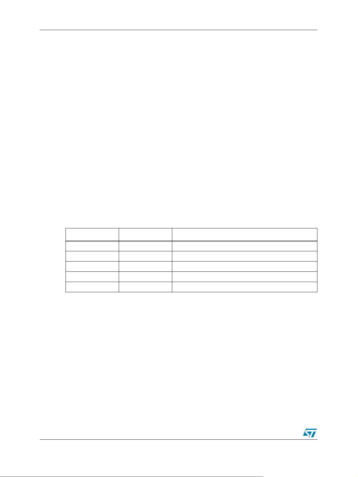
Table 1. File Library Description
File Description
Device_SCR.h Smart Card definiti ons, types definitions and function prototypes
Device_SCR.c T0 protocol management
sc.h,sc.c Physical layer
6/40
Page 7

AN2284 2 Smart Card Reader Using STR710: Overv iew
2 Smart Car d R ea d er Usi ng STR710: Over view
A smart card reader was developed using the STR710 ARM7TDMI powered microcon troller
and a basic HW to interface 5V powered smart card.
The Smart Card Library was developed in order to support ISO7816-3/4 specification.
7/40
Page 8

3 Device Description AN2284
3 Device Description
3.1 STR710 Microcontroller
Here is a brief description of the STR710 microcontroller. Please refer to the STR710 datasheet
for a detailed description.
● Memories
- 272KB (256+16K) FLASH program memory (100,000 cycles endurance, data retention
20 years)
- 64KB RAM
- External Memory Interface (EMI) for up to 4 banks of SRAM, Flash, ROM
- Multi-boot capability
● Clock, Reset and Supply Management
- 3.3V application supply and I/O interface
- Embedded 1.8V voltage regulator for core supply
- 0 to 16MHz external main oscillator
- 32kHz external backup oscillator
- Internal PLL for CPU clock
- Up to 50MHz CPU operating frequency when executing from flash
- Realtime Clock for clock-calendar function
- 4 power saving modes: SLOW, WAIT, STOP and STANDBY modes
● Nested interrupt controller
- Fast interrupt handling with multiple vectors
- 32 vectors with 16 IRQ priority levels
- 2 maskable FIQ sources
● Up to 48 I/O ports
- 30/32/48 multifunctional bidirectional I/O
- 14 ports with interrupt capability
● 5 Timers
- 16-bit watchdog timer
Four 16-bit timers each with: 2 input captures, 2 output compares, PWM and pulse counter
● 10 Communications Interfaces
- 2 I2C interfaces (1 multiplexed with SPI)
- 4 UART asynchronous serial communications interfaces
- Smart Card ISO7816-3 interface on UART1
- 2 BSPI synchronous serial interfaces
- CAN interface (2.0B Active)
8/40
Page 9

AN2284 3 Device Description
- USB v 2.0 Full Speed (12Mbit/s) Device Function with Suspend and Resume support
- HDLC synchronous communications interface
● 4-channel 12-bit A/D Converter
- Conversion time:
- 4 channels: up to 500Hz (2 ms)
- 1 channel: up to 1kHz (1 ms)
- Conversion range: 0 to 2.5V
● Development Tools Support
- JTAG with debug mode trigger request
9/40
Page 10
4 SC Peripheral Descript ion AN2284
4 SC Perip h er al Description
4.1 Introduction
The SmartCard Interface is an extension of UART1; for the description of the UART registers,
please refer to STR710 datasheet. The SmartCard interface is designed to support
asynchronous protocol SmartCards as defined in the ISO7816-3 standard.
With SmartCard mode enabled, UART1 is configured as:
- eight data bits plus parity
- 0.5 or 1.5 stop bits
A 16 bit counter and the SmartCard clock generator provide the clock to the SmartCard. GPIO
bits in conjunction with software are used to provide the rest of the functions required to
interface to the SmartCard.
The inverse signalling convention as defined in ISO7816-3, inverted data and MSB first, is
handled in the software.
4.2 External Interface
Table 2. Smart Card Pins
Pin Number Pin Name Function
P0.12 SCCIk Smart card clock
P0.10 I/O I/O serial data: open drain @ both ends
Any GPIO RST Rese t to card
VCC Supply voltage
Vpp Programming voltage
The ScRST, ScCmdVpp (command for Vpp), ScCmdVcc (command for Vcc), and ScDetect
signals (signal for card detection) are provided by GPIO bits of the IO ports under software
control. Programming the GPIO bits of the port for alternate function modes connects the UART
TXD data signal to the ScDataOut pin with the correct driver type and the clock generator to the
ScClk pin.
4.3 Protocol
The ISO standard defines the bit times for the asynchronous protocol in terms of a time unit
called an ETU which is related to the clock frequency input to the card. One bit time is of length
one ETU. The UART transmitter output and receiver input need to be connected together
externally. F or the transmission of data from the STR71x to the SmartCard, the UART will need
to be set up in SmartCard mode.
10/40
Page 11
AN2284 4 SC Peripheral Descr iption
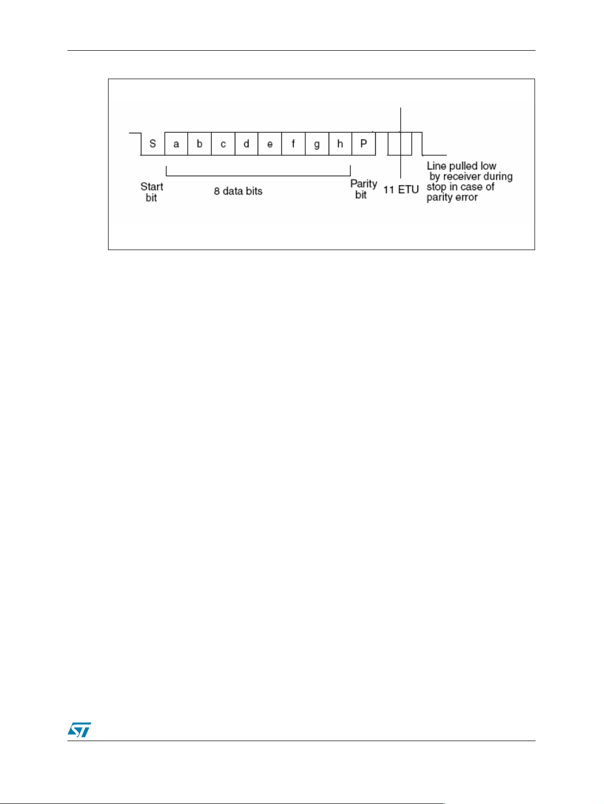
Figure 1. ISO 7816-3 Asynchronous Protocol
4.4 Smart Card Clock Generator
The SmartCard clock generator provides a clock signal to the connected SmartCard. The
SmartCard uses this clock to derive the baud rate clock for the serial I/O between the
SmartCard and another UART. The clock is also used for the CPU in the card, if present.
Operation of the Smart Card interface requires that the clock rate to the card is adjusted while
the CPU in the card is running code so that the baud rate can be changed or the performance
of the card can be increased. The protocols that govern the negotiation of these clock rates and
the altering of the clock rate are detailed in ISO7816-3 standard.
The clock is used as the CPU clock for the Smart Card, therefore updates to the microcontroller
clock rate must be synchronized to the SmartCard clock, i.e. the clock high or low pulse widths
must not be shorter than either the old or new programmed value.
11/40
Page 12
5 SC Reader: Basic Hw For 5v Card AN2284
5 SC Reader: Basic Hw For 5v Card
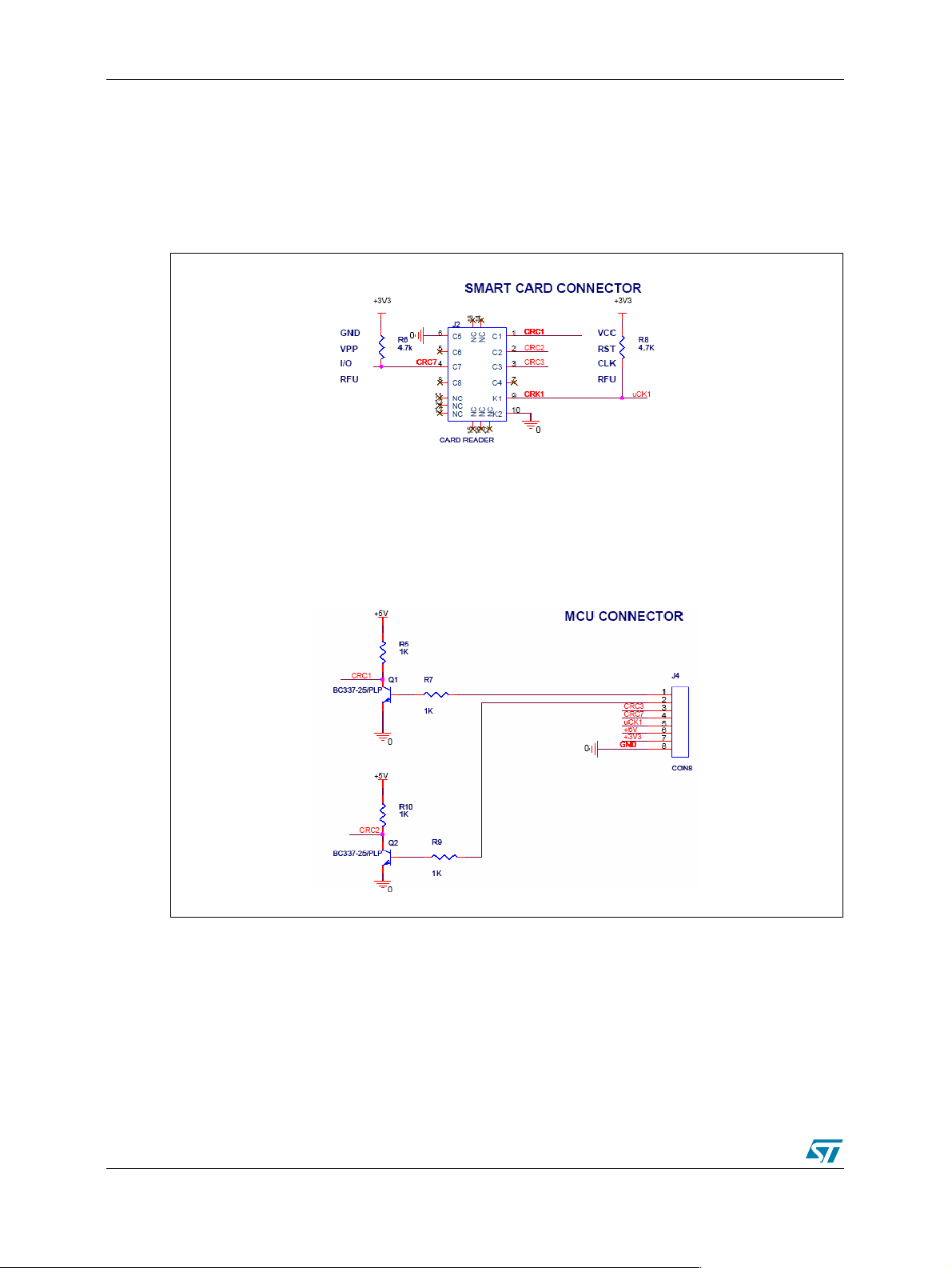
Some adjustments are needed when using a 5V powered smart card. Figure 2. shows how to
interface a 5V smart card with the microcontroller (STR710):
Figure 2. Basic Hardware For 5V Card Interface
12/40
Page 13

AN2284 6 SC ISO7816: Protocol Overview
6 SC ISO7816: Protocol Overview
6.1 Introduction
"ISO7816: Identification Cards Integrated Circuit(s) Cards with Contacts" provides the basis to
transition the relatively simple identification card from a token that can be compromised through
forgery, theft, or loss into a tamper-resistant and "intelligent" integrated circuit card (ICC), more
popularly known as a smart card. ISO 7816 includes at least six approved parts and has
several additional parts under review:
● Part 1, Physical characteristics
● Part 2, Dimensions and location of the contacts
● Part 3, Electronic signals and transmission protocols
● Part 3, Amendment 2-Revision of protocol type selection
● Part 4, Inter-industry commands for interchange
● Part 5, Numbering system and registration procedure for application identifiers
6.2 ISO 7816-2 - Pins Location
ISO 7816-2 specifies an ICC with eight electrical contacts present in a standardized position on
the front face of the card. These are referred to as C1 through C8. Some of these contacts are
electrically connected to the microprocessor chip embedded within the card; some are not,
having been defined to allow for enhancements but unused at the present time. The picture
below depicts the contacts positions.
Figure 3. Contact Definitions for Smart Cards
13/40
Page 14

6 SC ISO7816: Protocol Overview AN2284
6.2.1 Pin Assignment Table 3. Pin Assignment
C1: Vcc=5V C5:Gnd
C2: Reset C6: Vpp
C3: Cloc k C7: I/O
C4: RFU C8: RFU
14/40
Page 15

AN2284 7 ISO 7816-3 - Electronic Signal and Transmission Protocol
7 ISO 7816 -3 - Elect ronic Signal and Transmission
Protocol
ISO 7816-3 begins to delve into the specification of the "intelligent" aspects of the smart card.
This standard describes the relationship between the smart card and the reader as one of
"slave" (the smart card) and "master" (the reader). Communications are established by the
reader signaling to the smart card through the contacts noted previously and are continued by
the smart card responding accordingly.
Communication between the card and reader proceed according to various state transitions
illustrated in F igure 3..
Figure 4. Reader and Card FSM
The communication channel is single-threaded; onc e the reader sends a command to the
smart card, it blocks until a response is received.
15/40
Page 16

7 ISO 7816-3 - Electronic Si gnal and Transmission Protocol AN2284
7.0.1 Card Power-on and Reset
When a card is inserted into a reader, no power is applied to any of the contacts. The chip on
the card could be seriously damaged by applying power to the wrong contacts, and this
situation could easily occur if a card were inserted across powered contact points. The contacts
remain unpowered until an edge detector determines that the card is properly aligned with the
contact points to within some acceptable (for the reader) mechanical tolerance.
When the reader detects that the card is properly inserted, power is applied to the card. First,
the contacts are brought to a coherent idle state, as shown in Table 3.4. A reset signal is then
sent to the card via the RST contact line. The idle state occurs when the power (VCC) contact
is brought up to a normal, stable operating voltage of 5V . An initial power setting of 5V is always
applied first, even though some microprocessor chips being introduced operate at 3V when in
an I/O state. The I/O contact is set to a reception mode on the reader side and a stable clock
(CLK) is applied. The reset line is in a low st at e. I t must remain in a low state for at least 40,000
CLK cycles before a valid reset sequence can be started by the reader, raising the reset line to
a high state.
Figure 5. Answer to Reset
7.0.2 Data Transfer
Data transfer between the reader and the card occurs through the concerted action of two of
the contact lines: CLK and I/O. The I/O line conveys a single bit of information per unit of time
as defined by the CLK depending on its voltage relative to GND. A 1 bit can be conveyed either
through a +5V value or through a 0V value. The actual convention used is determined by the
card and is conveyed to the reader through the "initial character" of the ATR, which is
referenced as TS. To transfer 1 byte of information, 10 bits are actually moved across the I/O
line; the first is always a "start bit" and the last is always a parity bit used to convey even parity.
Considering that the I/O line can be (in one bit period) either in a high (H) state or a low (L)
state, the TS character of the form HLHHLLLLLLH signals that the card wants to use the
"inverse convention," meaning that H corresponds to a 0 and L corresponds to a 1. A TS
16/40
Page 17

AN2284 7 ISO 7816-3 - Electronic Signal and Transmission Protocol
character of the form HLHHLHHHLLH signals that the card wants to use the "direct
convention," meaning that H corresponds to a 1 and L corresponds to a 0.
The direct convention and the inverse convention also control the bit ordering with each byte
transferred between the card and the reader. In the direct convention, the first bit following the
start bit is the low-order bit of the byte. Successively higher-order bits follow in sequence. In the
inverse convention, the first bit following the start bit is the high-order bit of the byte.
Successively lower-order bits follow in sequence. Parity for each byte transferred should be
even; this means that the total number of 1 bits in the byte, including the parity bit, must be an
even number.
The I/O line comprises a half-duplex channel; that is, either the card or the reader can transmit
data over the same channel, but they both cannot be transmitting at the same time. So as part
of the power-up sequence, both the reader and the card enter a receive state in which they are
listening to the I/O line. With the commencement of the reset operation, the reader remains in
the receive state while the card must enter a send state in order to send the ATR back to the
reader. From this point on, the two ends of the channel alternate between se nd states and
receive states. With a half-duplex channel, there is no reliable way for either end to
asynchronously change a state from send to receive or from receive to send. Rather, if this is
desired, that end must go into a receive state and allow a time-out of the operation in progress;
then a reader end will always try to re-establish a known sequence by re-entering a send state.
The CLK and I/O lines can support a wide variety of data transmission speeds. The specific
speed is defined by the card and is conveyed back to the reader through an optional character
in the ATR. The transmission speed is set through the establishment of one bit time on the I/O
line, which means that an interval is established at which the I/O line may be sampled in order
to read a bit and then each successive bit. This time is defined as an elementary time unit (etu)
and is established through a linear relationship between several factors. Note that the TS
character was returned before any definition of the etu could be made. This is possible because
the etu during the ATR sequence is always specified to be etu
the CLK frequency is always between 1MHz and 5 MHz; in fact, the frequency is almost always
selected such that the initial data transfer rate is 9,600 bits per second.
7.0.3 Answer to Reset: ATR
Once an RST signal is sent from the reader to the card, the card must respond with the first
character of the ATR within 40,000 CLK cycles. The card might not respond with an ATR for a
number of reasons, the most prevalent being that the card is inserted incorrectly into the reader
(probably upside down). In some instances, the card may not be functioning because it has
been damaged or broken. Whatever the case, if the ATR is not returned within the prescribed
time, the reader should begin a sequence to power down the card. During this sequence, the
reader sets the RST, CLK, and I/O lines low and drops voltage on the VCC line to nominal 0
(that is, less than 0.4V).
The ATR is a string of characters returned from the card to the reader following the successful
completion of the power-up sequence. As defined in ISO/IEC 7816-3, the ATR consists of 33 or
fewer characters comprising the following elements:
● TS - a mandatory initial character
● T0 - a mandatory format character
● TAi TBi TCi TDi-optional interface characters
● T1, T2,TK-optional historical characters
● TCK - a conditional check character
=372/(CLK frequency) where
0
17/40
Page 18

7 ISO 7816-3 - Electronic Si gnal and Transmission Protocol AN2284
The historical characters can be defined at the discretion of the card manufacturer or the card
issuer. These characters are typically used to convey some type of designation of the type,
model, and use of this specific card. When used in this way, the historical characters provide a
modest mechanism through which system s can autom atically detect the use of an inserted
card (within that system) and can initiate other actions (or software) accordingly. The check
character provides a mechanism through which the integrity of the ATR can be measured; that
is, whether a transmission error has occurred in sending the characters from the card to the
reader.
The struc ture of the ATR is illustra te d in Table 4. As discussed previously, the initial TS
character is used to establish the bit-signaling and bit-ordering conventions between the reader
and the card. The T0 character is used to signal the presence or absence of subsequent
interface characters or historical characters. The interface characters are used to tailor the
characteristics of the I/O channel, including the specific protocol used by the card and reader
during subsequent exchange of commands (from the reader to the card) and responses (from
the card to the reader). The historical characters, if present, are used to convey cardmanufacturer-specific information from the card to the read, and hence to the application
system being served by the reader. There is really no established standard for the information
presented in the hist orical bits.
The total length of the ATR sequence is limited to 33 bytes and must adhere to the following
format:
Table 4. The Answer-to-Reset Structure
Character ID Definition
Initial C har a ct e r S ection TS Mandat or y initia l ch a r ac t er
Format Character Secti on T0 Indicator for presence of interface charac ter s
Interface Character Section
Historical Char acter Section
Check Character Sect ion
TA
1
TB
1
TC
1
TD
1
TA
2
TB
2
TC
2
TD
2
TA
3
...TD
i
T1 Card specific information
...TK (Maximum of 15 characters)
TCK
2
Global, codes F1 and D1
Global, codes 11 and Pl1
Global, code N
Codes Y2 and T
Specific
Global, code Pl2
Specific
Codes Y3 and T
TAi, TBi and TCi are specific
Codes Y
Optional check character
i+1
and T
18/40
Page 19

AN2284 7 ISO 7816-3 - Electronic Signal and Transmission Protocol
7.1 ISO 7816-4 - Smart Card Commands
The previous chapter discussed the answer-to-reset (ATR) mechanism, which establishes a
basic communication channel betwee n the smart card and the reader. This channel is a halfduplex physical channel. This chapter investigates the use of more complex protocols on top of
this physical channel.
A link-level communication protocol resides directly on top of the physical channel, providing
error-free communication between the reader and the smart card. Once this link level protocol
is established, application-level protocols can be defined. ISO 7816-4 defines two such
application-level protocols:
● File system API providing a set of functions to manipulate files (e.g. read, write, select etc.)
● Security service API allowing the smart card and the reader to mutually authenticate
themselves and also to encrypt data to be exchanged between the card and the reader.
ISO 7816-4 defines a protocol message structure to support the application protocol APIs. This
message structure consists of application protocol data units (APDUs) which are exchanged
between the reader application and the smart card application by the link level protocol. This
chapter will provide an overview of the file access and security APIs. A more detailed
description can be found in Appendix A, "The ISO 7816-4 Command set".
7.1.1 The T0 Protocol
The T=0 protocol is a byte-oriented protocol where a character is transmitted across the
channel between the reader and the card. In addition, error handling is performed on each byte
by looking at the parity bit. If the actual parity bit does not correspond to the parity of the
transmitted data, then an error must have occurred. In the T=0 protocol, the receiving side
signals that it requires the byte to be retransmitted in the case of detecting a p ari ty error. This is
done by holding the I/O line low (normally the I/O line is set high preceding the transfer of a
byte). When the transmitting side detects this, it resends the byte that was previously received
in error.
The reader and the smart card exchange data structures known as transmission protocol data
units (TPDUs). It consists of two distinct structures:
● a command that is sent from the reader to the card
● a response that is sent from the card to the reader
The command header includes the following five fields each of one byte in length:
● CLA: class designation of the command set to establish a collection of instructions
● INS: specifies a specific instruction from within the set of instructions
● P1: used to specify the addressing used by the [CLA, INS] instruction
● P2: also used to specify the addressing used by the [CLA, INS] instruction
● P3: specifies the number of data bytes transferred to or from the card as part of the [CLA,
INS] instruction execution.
Each value of CLA defines an application-specific set of instructions. Table 5. below lists values
for some sets of instructions.
19/40
Page 20

7 ISO 7816-3 - Electronic Si gnal and Transmission Protocol AN2284
Table 5. CLA Instruction Set Definitions
CLA Byte Instruction Set
0X ISO 7816-4 instructions (files and security)
10 to 7F Reserved for future use
8X or ISO 7816-4 instruc ti ons
AX Application/vendor specific instructions
B0 to CF ISO 7816-4 instructions
D0 to FE Application/vendor specific instructions
FF Reserved for protocol type selection
The INS byte is used to identify a specific instruction within a class of instructions identified by
the value of CLA.Table 6. lists the instructions in the ISO 7816-4 standard used to access file
system and security functions.
Table 6. ISO 7816-4 INS Codes
INS Value Command Name INS Value Command Name
0E Erase Binary C0 Get Response
20 Verify C2 Envelope
70 Manage Channel CA Get Data
82 External Authentic ate D0 Write Binary
84 Get Challenge D2 Write Record
88 Internal Authenticate D6 Update Binary
A4 Select File DA Put Data
B0 Read Binary DC Update Record
B2 Read Record(s) E2 Append Record
The parameters P1 and P2 are defined at the link level but are actually dependent on the
specific instruction (application level). They provide control or addressing parameters for the
various application-specific instructions. For example, in the Select File instruction, P1 is used
to indicate how the file will be referred to (by identifier, name, path etc.) and P2 offers further
refinement as to which file is to be selected. P3 defines the number of bytes to be transmitted
during the execution of the INS specified instruction. The convention used to indicate
movement of data is card-centric i.e. outgoing refers to data moving from the card to the reader
and incoming refers to data moving from the reader to the card.
For each command TDPU sent from the reader, a response TPDU is sent by the card. The
response includes three mandatory fields and one optional field (all one byte in length):
● ACK: indicates that the card has received the [CLA, INS] command
● NULL: used for flow control on the I/O channel by the card. It signals (to the reader) that
the card is still processing the command and so the reader must wait before sending
another command
● SW1: status response of the current command
● SW2: (optional) also conveys a status response to the reader
20/40
Page 21

AN2284 7 ISO 7816-3 - Electronic Signal and Transmission Protocol
The ACK byte is a repeat of the INS byte from the command TPDU. If the response does not
reach the reader within a specified time, the reader may initiate a RST sequence to restart the
protocol between the reader and the card. This can be prevented if the reader receives at least
one NULL byte from the card. SW1 informs the reader of the result of the requested instruction.
The values allowed for SW1 are defined as part of the application protocol. Some instructions
require the card to send data to the reader. In this case SW2 is returned to the reader,
triggering the reader to execute a GetResponse co mm and. The c ard w ill t hen return th e d ata
bytes generated by the execution of the previous command.
7.2 Application Level Protocols
The ISO 7816-4 standard addresses two areas of functionality for application software:
● File system: A set of functions is provided in the form of an API. By using this API
application software on the reader side can access files in the file system.
● Security functions: These can be used to limit access to application software or to files on
the card.
The T=0 protocol is used to support application-level protocols between the smart card
application and the reader application. These application protocols exchang e data structures
called application protocol data units (APDUs). The following diagram illustrates this
architecture:
Figure 6. Application Communication Architecture
The APDU structure defined by ISO 7816-4 is very similar to the TPDU structure used in the
T=0 protocol. In fact, when an APDU is transported by the T=0 protocol, the elements of the
APDU directly overlay the elements of the TPDU.
21/40
Page 22

7 ISO 7816-3 - Electronic Si gnal and Transmission Protocol AN2284
7.2.1 The ISO 7816-4 APDU
There are two types of messages used to support the ISO 7816-4 application protocols: the
command APDU (sent from the reader to the card) and the response APDU (sent from the card
to the reader).
Figure 7. The Command APDU Structure
The command APDU consists of a header and a body (this can be seen in the diagram above).
The header includes CLA, INS, P1 and P2 fields. As in the T=0 protocol, CLA and INS specify
an application class and instruction. P1 and P2 are used to qualify specific instructions and are
given specific definitions by each [CLA, INS] instruction. The body of the APDU can vary in size
and is used to transmit data to the card's APDU processor as part of a command or to convey a
response from the card to the reader. The Lc field specifies the number of bytes to be
transmitted to the card as part of the instruction i.e. the length of the data field. The data field
contains information that must be sent to the card to allow its APDU processor to execute the
command specif ied in the AP DU . Th e Le field specifies th e number of bytes that will be
returned to the reader in the response APDU.
The body of the APDU can take on four different forms:
● Case 1: No data is transferred to or from the card, so the APDU only contains the header.
● Case 2: No data is transferred to the card, but data is returned from the card. The body of
the APDU only contains a non-null Le field.
● Case 3: Data is transferred to the card, but none is returned from it. The body of the APDU
includes the Lc and data fields.
● Case 4: Data is transferred to the card and is also returned from the card as a result of the
command. The body of the APDU includes the Lc, data and Le fields.
Figure 8. The Response APDU Structure
The response APDU has a much simpler structure than that of the command APDU. It consists
of a body and a trailer. The body is either null or it includes a data field - depending on the
specific command. The length of the data field is determined by the Le field in the
corresponding command APDU. The trailer consists of up to two fields of status information
22/40
Page 23

AN2284 7 ISO 7816-3 - Electronic Signal and Transmission Protocol
called SW1 and SW2. These fields return a status code in which one byte is used to specify an
error category and the other is used to specify a command-specific status or error indication.
7.2.2 The File System API
The file system is used on the nonvolatile memory or EEPROM. It is defined as a simple
hierarchical structure (similar to conventional file systems). The file system may contain three
types of files (identified by a 2-byte identifier):
● Master file (MF)
● Dedicated file (DF)
● Elementary file (EF)
There is one master file found on each smart card and it is the root of the file system. A master
file may contain dedicated files or elementary files. The file identifier reserved for the master file
is 3F00. The directory file is essentially a container (or directory) for elementary files - a DF may
contain zero or more EFs. Dedicated files partition the smart card into an ordered structure of
elementary files. A dedicated file must be given a unique file identifier within the dedicated file
or master file that contains it - allowing for a unique path for each file. A dedicated file can also
be referenced by name (1-16 bytes long). The naming convention can be found in ISO 7816-5.
An elementary file is a leaf node in the hierarchy and contains the actual data. An elementary
file can be identified by a 5-bit identifier within a dedicated file. This file system hierarchy is
illustrated in Figure 9.
Figure 9. The Smart Card File System Architecture
There are four types of elementary files:
● Transparent file
● Linear, fixed-length record file
● Linear, variable-length record file
● Cyclic, fixed-length record file
A transparent file is essentially a string of bytes i.e. an unstructured binary file. Consequently a
byte offset from the start of the file is required when data is to be read or written to this type of
file. In addition, a command to read or write to a transparent file will contain the length of the
byte string to be read or writt e n to the fil e .
23/40
Page 24

7 ISO 7816-3 - Electronic Si gnal and Transmission Protocol AN2284
Fixed and variable length files contain records that are identified by a sequence number. In a
fixed-length record file, all the records contain the same number of bytes. In contrast, a
variable-length record file contains records that may vary in length. As a result, variable-length
record files have a higher overhead in read/write access times as well as a higher
administrative overhead required by the file system.
A cyclic file allows applications to access records in a consistent and transparent manner. It c an
be thought of as a ring of files. Write operations are performed on the next physical record in
the ring.
7.2.3 The ISO 7816-4 Functions
The few functions that are defined in ISO 7816-4 for selecting, reading and writing to files will
be briefly discussed below.
Select File:
This command establishes a logical pointer to a particular file in the smart card's file system.
This pointer is required for any file manipulation operation. Access to the smart card's file
system is not multithreaded, however it is possible to have several file pointers defined at any
point in time. This is accomplished by the Manage Channel command, which establishes
multiple logical channels between the reader side application and the card. This allows different
files on the card to be in various states of access by the reader application at the same time.
The identification of the file can be provided in the following ways:
● file identifier (2-byte value)
● DF name (string of bytes)
● path (concatenation of file identifiers)
● short ID
Note that not all smart cards support all four naming mechanisms.
Read Binary:
This command is used by the application on the reader side to retrieve a part of an EF on the
card. However, the EF must be a transparent file (not record-oriented). If the Read Binary
command is attempted on a record-oriented EF, the command will abort with an error indicator
being returned from the card.
The Read Binary command takes two parameters: an offset pointer from the start of the file to
the initial byte to be read, and the number of bytes to be read and returned to the reader.
Write Binary:
This command is used to insert data into a transparent EF on the card. This command can be
used to set a series of bytes in the EF (i.e. set selected bits within a specified byte to a value of
1), clear a series of bytes or perform a write of a series of bytes in the EF.
24/40
Page 25

AN2284 7 ISO 7816-3 - Electronic Signal and Transmission Protocol
Update Binary:
A reader-side application can utilize this command to directly erase and store a contiguous
sequence of bytes in a transparent EF on the card. It effectively functions as a write command
i.e. a string of bytes provided in the command are written into the EF on the card. The input
parameters consist of an offset pointer from the start of the file as well as the number of bytes
to be written.
Erase Binary:
The Erase Binary command is used to clear bytes within a transparent EF on a card. Similarly
to the previous commands, the input parameters comprise an offset from the start of the EF to
the segment of bytes to be erased as well as the number of bytes to be erased.
Read Record:
This command is used to read and return the contents of one or more records in an EF on a
card. Unlike the previous command, the EF for the Read Record command must be a recordoriented file. If it is applied to a transparent EF, the command will abort and an error will be
returned to the reader.
The following may be returned from this command, depending on the input parameters:
● A specified record
● All the records from the beginning of the file to a specific record
● All the records from a specific record to the end of the file
Write Record:
This command is used to write a record into a record-oriented EF. As with the Write Binary
command, this command can be used to write a record into an EF, set or clear specific bits
within a specific record in an EF.
Append Record:
The Append Record command is used to add a record to the end of a linear, record-oriented EF
or to write the first record to a cyclic, record-oriented EF on a card.
Update Record:
This command writes a specific record into a record-oriented EF on a card. As with the Update
Binary command, the old record is erased and the new one is written into the EF.
Get Da ta:
This command reads and returns the contents of a data object stored within the file system on
the card. The Get Data command is card-specific as the definition of a data object varies
between diffe rent ca rds.
Put Data:
25/40
Page 26

7 ISO 7816-3 - Electronic Si gnal and Transmission Protocol AN2284
This command (as the name suggests) puts information into a data object on the card. As with
the previous command, this is a card-specific command.
7.2.4 The Security API
Each component of the file system on a smart card has an associated list of access properties.
The access properties ensure that only authorized parties are allowed to access the particular
component of the file system. The authentication can be simple, such as requiring the reader to
provide a predefined personal identification number (PIN). Alternatively, it may be more
complicated, such as requiring the reader to prove that it possess some shared secret with the
card (e.g. a key) by encrypting or decrypting a string of bytes provided by the card.
A few of the functions provided by the security API are briefly discussed below.
Verify:
This command is sent by the application on the reader side to the security system on the card.
Its purpose is to convince the card that the reader knows a password maintained by the card in
order to restrict access to sensitive information stored on the card. The password-type
information may be associated with a specific file or to some or all of the file hierarchy. If the
Verify command fails i.e. the reader provides an incorrect password, an error is returned to the
reader.
Internal Authenticate:
This command allows the card to authenticate itself to the reader by proving that it possesses a
secret key shared with the reader. The reader application software first generates a random
number and encrypts it with some algorithm known to both card and reader. This constitutes a
challenge to the card. The card then decrypts this challenge with the secret key (that is stored
on the card) and sends the resulting data back to the reader. If the data received by the reader
matches the random number that it generated then the reader application software is assured
of the identity of the card.
Ext e r n a l Authe n ticate:
This command is used in conjunction with the Get Challenge command to enable the reader
application software to authenticate itself to the card. The reader receives challenge data (a
random number) from the card and encrypts it with a secret key. This is then sent to the card
using the External Authenticate command. The card decrypts the data and compares it to the
random number that it generated in the previous Get Challenge command . If there is a match,
then the card is assured of the identity of the reader application.
Get Challenge:
This command is sent by the reader to the card. Its purpose is to provide the reader application
with a random number generated by the smart card. As previously described, this number is
used in the External Authenticate command.
Manage Channel:
26/40
Page 27

AN2284 7 ISO 7816-3 - Electronic Signal and Transmission Protocol
The Manage Channel command is used by the reader application to open and close the logical
communication channels between it and the card. Initially the card opens a basic
communication channel by establishing an application-level protocol with the reader application
through the completion of an ATR sequence. This channel is then used to open or close
additional logical channels through the Manage Channel command.
Envelope:
This command supports the use of secure messaging using the T=0 protocol. It enables an
APDU to be encrypted and then incorporated into the Envelope command's data section (of its
APDU). The APDU processor on the card can then extract and execute the command.
Get Response:
As with the previous command, the Get Response command allows the use of the T=0 protocol
for transferring APDUs. The Case 4 type of APDU cannot be supported by the T=0 protocol i.e.
it is not possible to send a block of data to the card and then receive a block of data in return.
So when using the T=0 protocol, the initial command results in a response which indicates that
more data is waiting to be sent by the card. The Get Response command is then used to
retr i e v e this da ta .
27/40
Page 28

8 SC Reader Lib: Descriptio n AN2284
8 SC Reader Lib: Description
The user may access a Smart card using directly the application layer. It allows to send/receive
ADPU commands to/from the smart card using the following user interface:
● u8 SC_Handler (u8 SC_Action, u8 *Data_to_SC, u8 Data_lenght, u8 P1, u8 P2,
SC_State *SC_state, u16 *CmdStatus, u8 *Data_from_SC)
8.1 SC parameters
8.1.1 SC_Action
The user has to specify which action he wants to perform on the smart card using the
SC_Action parameter. Actions available are:
● Data Area Management commands
- SC_SELECT_FILE
- SC_GET_RESPONCE
- SC_STATUS
- SC_ U PD ATE_BINA RY
- SC_ R EAD_BINARY
- SC_WRITE_BINARY
- SC_ U PD ATE_RECO R D
- SC_READ_RECORD
● Administrative Commands
- SC_ C R EATE_FILE
● Safety Management Commands
- SC_VERIFY
- SC_CHANGE
- SC_UNBLOCK
- SC_EXTERNAL_ AU TH
- SC_GET_CHALLENGE
● Answer to Reset Commands
- SC_GET_A2R
8.1.2 SC_State
SC_State informs the user about the smart card state and allows to power off the smart card.
The smart card states are:
- SC_POWER_OFF
- SC_POWER_ON
28/40
Page 29

AN2284 8 SC Reader Lib: Descri pti on
- SC_RESET_L OW
- SC_RESET_HIG H
- SC_ACTIVE
- SC_ACTIVE_O N _T0
● SC_POWER_OFF
No power is provided to the smart card (Vcc=0); the STR7 smart card peripheral is
disabled. No clock is provided to smart card.
● SC_POWER_ON
The smart card peripheral is enabled and initialized; no power is provided to the smart card;
no clock is provided to the smart card.
● SC_RESET_LOW and SC_RESET_HIGH
In SC_RESET_LOW RST, the pin on the smart card (pin 2) is hold to zero (R ST =0) .
Vcc=5V is provided to the smart card; clock CLK is provided to the smart card. Answer to
reset (A TR) procedure begins. The reader waits for an ATR frame from the smart card. If no
answer is received, the reader forces reset pin RST high (RST=1) and waits again for an
answer to reset in the SC_RESET_HIGH state.
● SC_ACTIVE
If an answer to reset is received, the reader goes in active state and decodes the ATR
frame. It returns information about the used protocol.
● SC_ACTIVE_ON_T0
If the used protocol is T0, the reader goes in SC_ACTIVE_ON_T0 state and allows to send
commands to the smart card.
29/40
Page 30

8 SC Reader Lib: Descriptio n AN2284
ATR received with RST=0
No ATR received
No ATR received
T0 protocol
Figure 10. State Machine for Smart Card Operation
Power off
User force power on
Power on
User power off smart card
8.1.3 CmdStatus
CmdStatus retrieves the smart card status response related to the selected ADPU com man d
according the ISO7816 standard.
Possible card answers:
- SC_EF_SELECTED
- SC_DF_SELECTED
- SC_ O P _ T ERMINATED
- SC_DF_EXISTENT
Reset low
No T0 protocol
Reset high
ATR receiv ed with RS T=1
Active
Acti v e on T0
8.2 How to Send ADPU Commands to SC
30/40
- SC_EF_NOT_SELECTED
- SC_ID_NOT_FOUND
- SC_MEMORY_PROBLEM
- SC_WRONG_HEADER
- SC_WRONG_P1_P2
- SC_WRONG_LC_LE
A detailed description on how to use the SC_Handler( ) function to send the ADPU command to
SC and retrieve the card response is found below.
Page 31

AN2284 8 SC Reader Lib: Descri pti on
8.2.1 SC_SELECT_FILE
● SC_Handler (SC_SELECT_FILE, (u8 *) FileName, NULL_PARAM, NULL_PARAM,
&SC_state, &u16_status, void_pointer)
● Input
- FileName
It contains the 16 bit file identifier and the file type (EF or DF).
Example:
1) UserFile={0xAA,0xBB,EF}
2) UserDir={0xA0,0x00,DF}
● Output
- SC_ state
It returns the current smart card state
- u16_status
It returns the smart card response to SC_SELECT_FILE command
8.2.2 SC_GET_A2R
● SC_Handler (pvoid, NULL_PARAM, NULL_PARAM, NULL_PARAM, &SC_state,
&u16_status, A2Rframe)
● Input
- No input
● Output
- SC_ state
It returns the current smart card state
- u16_status
It returns the smart card response to SC_SELECT_FILE command
- A2Rframe
Pointer to an array which contains the smart card ATR frame
8.2.3 SC_GET_RESPONCE
● SC_Handler (pvoid, NULL_PARAM, NULL_PARAM, NULL_PARAM, &SC_state,
&u16_status, responce)
● Input
- No input
● Output
- SC_ state
It returns the current smart card state
- u16_status
31/40
Page 32

8 SC Reader Lib: Descriptio n AN2284
It returns the smart card status response to SC_GET_RESPONSE command
- response
It returns the smart card data response to SC_GET_RESPONSE command
8.2.4 SC_READ_BINARY
● SC_Handler (SC_RAED_BINARY, FileName, Byte_number, Offset_high, Offset_low,
&SC_state, &u16_status, responce)
● Input
- FileName
It contains the 16 bit file identifier
Example:
1) UserFile = {0xAA,0xA0}
- Byte_number
It contains size area (in byte) to read (valid only for EF)
- Offset_high, Offset_low
It contains the 16 bits offset where reading begins
● Output
- SC_state
It returns the current smart card state
- u16_status
It returns the smart card status response to SC_READ_ BINARY command
- response
- It returns the smart card data to read
8.2.5 SC_CREATE_FILE
● SC_Handler (SC_CREATE_FILE, FileName, FileSize, NULL_PARAM, NULL_PARAM,
&SC_state, &u16_status,pvoid
● Input
- FileName
It contains the 16 bit file identifier and the file type (EF or DF).
Example:
1) UserFile = {0xAA,0xA0, EF}
- FileSize
It contains size area (in byte) to allocate (valid only for EF)
● Output
)
- SC_state
It returns the current smart card state
32/40
Page 33

AN2284 8 SC Reader Lib: Descri pti on
- u16_status
- It returns the smart card status response to SC_CREATE_FILE command
8.2.6 SC_UPDATE_BINARY
● SC_Handler (SC_UPDATE_BINARY, FileUpdate, ByteNumber , Offset_high, Offset_low,
&SC_state, &u16_status, pvoid
● Input
- FileUpdate
Pointer to the array of byte to write
- ByteNumber
It contains size area (in byte) to read (valid only for EF).
- Offset_high, Offset_low
It contains the 16 bits offset where writing begins
● Output:
- SC_state
It returns the current smart card state
)
- u16_status
It returns the smart card status response to SC_UPDATE_BINARY command
8.2.7 SC_VERIFY
● SC_Handler (SC_VERIFY, Password, PWD_LENGHT, NULL_PARAM,
SC_VERIFY_PINX, &SC_s tate, &u16_status, pvoid
● Input
- Password
Pointer to the 8 byte array containing the pin to verify
- PWD_LENGHT
It contains a constant fixed to 8.
- SC_VERIFY_PINX
It indicates the PIN to verify (X=1…4).
● Output
- SC_ stat e
It returns the current smart card sta te
- u16_status
It returns the smart card status response to SC_UPDATE_BINARY command.
)
33/40
Page 34

9 SC Reader Lib: Parity Error Managem ent AN2284
9 SC Reader Lib: Parity Er ro r Man a ge me nt
In the T=0 protocol error handling is performed on each byte by looking at the parity bit. If the
actual parity bit does not correspond to the parity of the transmitted data, then an error must
have occurred; the receiving side signals that it requires the byte to be retransmitted in the case
of detecting a parity error. This is done by holding the I/O line low (normally the I/O line is set
high preceding the transfer of a byte). When the transmitting side detects this, it resends the
byte that was previously received in error.
9.1 Data Sent From Card to Reader
STR71xx is able to detect via HW a parity error on a received data pulling down the data line
during the stop bit.
9.2 Data Sent From R eader to Card
Vice versa if the smart card pulls down the I/O line to signal that a parity error occurred, the
user needs to check it by SW in order to resend the last data.
The SC library uses the
SC_ParityErrorIRQHandler(void) (device_SCR.c file) funtion which checks if the parity error
occurs and manages it.
Each time the
- sends a byte
- enables the reception
transmitted byte
- enables the Frame error interrupt source
After a byte is sent from the microcontroller to the card, the smart card peripheral captures the
data sent on the I/O line. If a parity error is detected from the card, the I/O line is pulled down
during the stop bits. A frame error event occurs and the related irq event invokes the
SC_ParityErrorIRQHandler(void) function. It resends the last data and disables the irq
source.
Uart_ByteSend_SCirq functio n is called it:
Uart_ByteSend_SCirq funtion (sc.c file) in conjunction with:
(UART_RxConfig(UART1 ,ENABLE)) in order to capture the
34/40
Page 35

AN2284 10 SC Reader Example
10 SC Reader Example
An example is provided in conjunction with the smart card library in order to help the user to
develop its custom application.
The example provides simple operations with a smart card such as file system exploration, files
and directories creation, read/write operation on files and pin verify on protected files.
10.1 Firmware Package Description
The STR71x_SClib_ v02 firmwa re package contains both the smart card library and the
example described in this section.
Figure 11. shows the directory tree. It consists of three main directories:
Figure 11. Firmware Package: Directory Tree
Table 7. Firmware Package: Directories Description
Directory Description
71x_lib It contains STR71xx li b fi les
SCF It contains the scatter files
SmartCard_Example
To run the example open the STR7_SC.prj file in the SmartCard_Example/realview directory.
10.2 Firmware Description
Three directories have been defined for the smart card directory tree:
MasterRoot[3]={0x3f,0x00, MF };
PrivateDir[3]={0xCA,0x 00, DF};
It contains:
- main.c, 71x_it.c and 71x_conf.h files
- realview project
35/40
Page 36

10 SC Reader Example AN2284
PublicDir[3]={0xDD,0x00,DF};
Figure 12. Smart Card Example: File System Description
At the end of the example:
PrivateDir directory will contains the PrivateFile file ;
- the
PublicDir directory will contains the PublicFile file;
- the
MasterRoot directory will contains the PwdFile file;
- the
The definition and the related file identifier code:
PrivateFile[3]={0xCA,0xA1,EF};
PublicFile[3]={0xCD,0x00,EF};
PwdFile[3]={0xDD,0xDD,EF};
10.2.1 Smart Card Start Up: Answer to Reset (A2R)
The first action to perform when the reader wants to access a card is the answer to reset
procedure. To this aim user has to invoke the SC_Handler as follows:
SC_state=SC_POWER_ON;
while (SC_state!=SC_ACTIVE_ON_ T0)
SC_Handler (SC_GE T _A2R , pvoid, NULL_PARAM, NULL_PARAM,
NULL_PARAM, &SC_state, &u16_status, card);
When a card is detected the A2R sequence is genereted, received and dec oded. If the
recognized protocol is the T0 protocol, the smart card state of the reader will be active
(SC_ACTIVE_ON_T0) and the smart card will be available for operations on the file system.
10.2.2 Reading a File at aSpecified Path
Suppose the specified path reading begins is:
MasterRoot/PrivateDir/PrivateFile
To reach it the user has to perform the following actions:
SC_Handler (SC_SELECT_FILE, (u8 *) MasterRoot, NULL_PARAM, NULL_PARAM,
NULL_PARAM, &SC_state, &u16_status, card);
SC_Handler (SC_ SEL EC T_F IL E, (u8 *) PrivateDir, NULL_PARAM, NULL_PARAM,
NULL_PARAM, &SC_state, &u16_status, response);
36/40
Page 37

AN2284 10 SC Reader Example
SC_Handler (SC_ SEL EC T_F IL E, (u8 *) PrivateFile, NULL_PARAM,
NULL_PARAM,NULL_PARAM, &SC_state, &u16_status, response);
Once the selected path is accessed, the user has to define the 16bit offset where he wants to
read and the number of bytes he wants to read:
offset_low=1;
offset_high=0;
byte_number=3;
SC_Handler (SC_READ_BINARY, (u8 *) PrivateFile, byte_number, offset_high, offset_low,
&SC_state, &u16_status, response);
10.2.3 Writing a File at a Specified Path
Suppose the user wants to write the PublicFile in the MasterRoot. He has to define the 16bits
offset where he wants to read and the number of bytes he wants to read.
In the example,
offset_low=1;
offset_high=0;
byte_number=18;
FileParamST[40]="SmartCardDemo";
SC_Handler (SC_UPDATE_BINARY, (u8 *) FileParamST, byte_number,
FileParam S T a rray will store the sequence the user wants to write.
offset_high,offset_low, &SC_state, &u16_status, response);
10.2.4 Creating a File at a Specified Path
Suppose the user wants to create a file in the MasterRoot.
SC_Handler (SC_SELE CT_F ILE , (u8 *) MasterRoot, NULL_PARAM, NULL_PARAM,
NULL_PARAM, &SC_state, &u16_status, card);
SC_Handler (SC_CREATE_FILE, (u8 *) PublicFile, 20,NULL_PARAM, NULL_PARAM,
&SC_state, &u16_status, response);
Where
20 is the size (in byte) of PublicFile.
10.2.5 Creating a File at a Specified Path With Pin Protection
Suppose the user wants to create a file in the MasterRoot/PublicDir directory.
SC_Handler (SC_SELE CT_F ILE , (u8 *) MasterRoot, NULL_PARAM, NULL_PARAM,
NULL_PARAM, &SC_state, &u16_status, card);
SC_Handler (SC_CREATE_FILE, (u8 *) PublicDir, NULL_PARAM,
NULL_PARAM,NULL_PARAM, &SC_state, &u16_status, response);
SC_Handler (SC_SELE CT_F ILE , (u8 *) PublicDir, NULL_PARAM,
NULL_PARAM,NULL_PARAM, &SC_state, &u16_status, response);
37/40
Page 38

10 SC Reader Example AN2284
PwdFile will be created with PIN1 enabled for read and write access:
SC_Handler (SC_CREATE_FILE, (u8 *) PwdFile, 40, SC_PIN1_W | SC_PIN1_R,
NULL_PARAM, &SC_state, &u16_status, response);
If the user verifies PIN1 for read/write operations,
PwdFile can be accessed. When the user
tries to verify a PIN, the related Pwd has to be specified. In this example the
following 8byte password is associated with PIN1:
Pwd={"1", "1", "1", "1", "1", "1", "1", "1"}
SC_Handler (SC_VER IF Y, (u8 *) Pwd, PWD_LENGHT, NULL_PARAM,SC_VERIFY_PIN1,
&SC_state, &u16_status, response);
After that he can be selected:
SC_Handler (SC_SELE CT_F ILE , (u8 *) PwdFile, NULL_PARAM,
NULL_PARAM,NULL_PARAM, &SC_state, &u16_status, response);
38/40
Page 39

AN2284 1 1 Revision History
11 Revision History
Date Revision Changes
05-Jan-2006 1.0 First edition
39/40
Page 40

11 Revision History AN2284
I
s
o
d
b
ct
t
ot
a
nformation furnished is believed to be accurate and reliable. However, STMicroelectronics assumes no responsibility for the consequence
f use of such information nor for any infringement of patents or other rights of third parties which may result from its use. No license is grante
y implic ation or oth erwise under any patent or patent rights of S T M i croelectro nics. Spec i fications me ntioned in th i s publication are s ubje
o change without notice. This publication supersedes and replaces all information previously supplied. STMicroelectronics products are n
uthoriz ed for use as crit ical components in life suppor t devices or sys tems without express writt en approval of STM i croelectronics.
The ST logo is a registered trademark of STM i croelectroni cs.
All other nam es are the property of their respective owners
Austra l i a - Be l gi um - Brazil - C anada - China - Czech Republic - Finland - France - Germany - Hong Kong - India - Israe l - It al y - Japan -
Malaysi a - M al ta - Morocco - Singapore - Sp ai n - Sweden - Switzerland - United Kingdom - United States of Ameri ca
© 2006 STMi croelectro ni cs - All rights reserved
STMicroelectronics group of companies
www.st.com
40/40
 Loading...