

Page 1
AN2248
APPLIC ATION NOT E
Designing with the STMUX1000L Ethernet Gigabit LAN Switch
Introduction
The STMUX1000L is an 8- to 16-bit bi-directional Multiplexer/Demultiplexer. It is designed f or appl ications
that require signal routing at 10/10 0/1000 Megabit Ether net speeds. The device integrates three Single
Pole Dual Throw (SPDT) Channels for LED support and is available in two different packages, the
TSSOP56 and QFN56.
This application note highlights various applications into which the STMUX1000L Gigabit LAN Switch can
be designed, such as PC Notebooks and do cking stations (see
several electrical characteristics impact high performance data transfer, including
■ low noise between signals,
■ low R
■ low C
, and
ON
and C
on
capacitance.
off
Additionally, the superior performance of the STMUX1000L is illustrated when it is compared to a
competitor’s device.
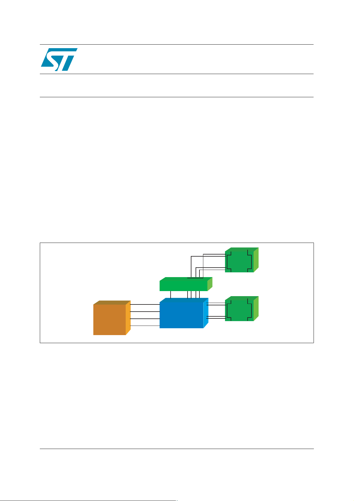
Figure 1
). These are applications where
Figure 1. Typical Docking Station/Notebook Connections
Docking Station
Docking Connector
SEL
MDI [1] +
10/100/1000
Base-T
MAC & PHY
MDI [1] –
MDI [4] +
MDI [4] –
STMUX1000L
LAN Switch
MDI [1] +
MDI [1] –
MDI [4] +
MDI [4] –
CAT5
Interface
Notebook
CAT5
Interface
AI11868
Rev 1.0
October 2005 1/9
http:/www.st.com
9
Page 2

AN2248 - APPLICATION NOTE
Contents
1 Evolution of Gigabit Ethernet Technology . . . . . . . . . . . . . . . . . . . . . . . . . 3
1.1 Typical Progression . . . . . . . . . . . . . . . . . . . . . . . . . . . . . . . . . . . . . . . . . . . . . 3
2 STMUX1000L Testing and Measurement . . . . . . . . . . . . . . . . . . . . . . . . . . . 4
Table 1. Testing Equipment . . . . . . . . . . . . . . . . . . . . . . . . . . . . . . . . . . . . . . . . . . . 4
2.1 –3dB Measurement . . . . . . . . . . . . . . . . . . . . . . . . . . . . . . . . . . . . . . . . . . . . . 5
Figure 2. –3dB Bandwidth Test Bench. . . . . . . . . . . . . . . . . . . . . . . . . . . . . . . . . . . . 5
Figure 3. –3dB Bandwidth Characteristics . . . . . . . . . . . . . . . . . . . . . . . . . . . . . . . . . 5
2.2 Cross-talk Measurement . . . . . . . . . . . . . . . . . . . . . . . . . . . . . . . . . . . . . . . . . 6
Figure 4. Cross-talk Measurement Test Bench . . . . . . . . . . . . . . . . . . . . . . . . . . . . . 6
Figu r e 5 . T y p i c a l Cros s-ta lk Results. . . . . . . . . . . . . . . . . . . . . . . . . . . . . . . . . . . . . . 6
3 Features and Benefits . . . . . . . . . . . . . . . . . . . . . . . . . . . . . . . . . . . . . . . . . . 7
Table 2. STMUX1000L Features and Benefits . . . . . . . . . . . . . . . . . . . . . . . . . . . . . 7
4 Revision History . . . . . . . . . . . . . . . . . . . . . . . . . . . . . . . . . . . . . . . . . . . . . . 8
2/9
Page 3

AN2248 - APPLICATION NOTE 1 Evolution of Gigabit Ethernet Technology
1 Evolution of Gigabit Ethernet Technology
Gigabit Ethernet evolved from the original 10Mbps Ethernet and 100Mb ps fast Ethernet
standards. At one time, many organizations believed that a 10Mbps connection would always
be adequate for the average business desktop user, and that 100Mbps would be needed only in
the “backbone” (the central network that links all of the Internet together).
Gigabit Ethernet technology increases the performance of the data transfer between servers
and desktops, thereby reducing the traffic flow in the congested areas.
It is also a good choice because it supports a high level of Quality of Service (QoS). QoS
methods are increasingly important for avoiding latency problems as voice, video, and data
share the same bandwidth for Next-Generation Networking (NGN) applications.
1.1 Typical Progression
Typical users of Gigabit Ethernet are the workgroups that usually need heavy bandwidth like
the engineering and R&D Depar t m ents, which not only use CAD, 3D modelling and
collaborative design, but also have more powerful workstations that can immediately take
advantage of a high-performance connection. Other specialized business categories like
medical imaging, graphic design or advertising production will also follow this new standard.
The transition to Gigabit Ethernet speeds and networ ks will happen in several phases which
are summarized as follows:
● Phase 1
High-performance Gigabit switches are used to aggregate backbone traffic.
● Phase 2
Gigabit Ethernet is switched and routed at the network backbone with switch-to-switch
connections.
● Phase 3
Greater server-to-switch bandwidth is deployed using a gigabit switch to support Gigabit
Ethernet network adapter cards, boosting ser ver connections to 1000Mbps.
● Phase 4
All servers have at least one Gigabit connection, and Gigabit becomes the standard for the
highest-demand desktops and workgroups.
● Phase 5
As PCs are replaced due to normal attrition, 10/100/1000 Mbp s network interfaces are
specified to replace 10/100Mbps connections.
● Phase 6
Servers are scaled to multi-Gigabit speeds. Older switches are replaced with Gigabit
switches to take Gigabit down to the desktop. Gigabit Ethernet becomes standard for
virtually all desktops.
3/9
Page 4

2 STMUX1000L Testing and Measurement AN2248 - APPLICATION NOTE
2 STMUX1 000 L Testing and Measuremen t
Basic testing instruments (see
page 6
Figure 3.
between the channels to enable a correct data transfer when the laptop is connected to the
docking station.
Table 1. Testing Equipment
) were used to perform the –3dB bandwidth and Cross-talk measurement s.
and
Figure 5.
Tektronics Dual Programmab le Power Supply Generator PS2521G
Agilent Technologies Network Anal yzer 300KHz to 3GHz E5070B
illustrate the importance of a very high bandwidth and low noise device
Table 1
Brand Model
) and benches (see
Figure 2 on page 5
and
Figure 4 on
4/9
Page 5

AN2248 - APPLICATION NOTE 2 STMUX1000L Testing and Measure me nt
2.1 –3dB Measurement
The STMUX1000L –3dB bandwi dth measurem ent is conducted as follows:
1. The STMUX1000L switch is connected to the testing circuit and turned ON.
2. A 10dBm sine signal is forced across the switch with a frequency sweep of 300KHz to
1GHz.
3. The output frequency values are checked to make sure they remain the same, while the
signal is reduced by –3dB (in the case of
Figure 2. –3dB Bandwidth Test Bench
Figure 3
, signal reduction starts at 506.668MHz).
V
IN
Testing Circuit
50Ω
50Ω
50Ω
50Ω
Network Analyzer
Source Input
50Ω
A
B
C
D
SEL
Figure 3. –3dB Bandwidth Characteristics
50Ω
A0
B0
A1
B1
C0
D0
C1
D1
50Ω
50Ω
50Ω
50Ω
50Ω
50Ω
50Ω
50Ω
V
OUT
AI11869
5/9
Page 6

2 STMUX1000L Testing and Measurement AN2248 - APPLICATION NOTE
2.2 Cross-talk Measurement
The STMUX1000L cros s-talk mea suremen t is conducted as follows:
1. The STMUX1000L switch is connected to the testing circuit and turned ON.
2. A 10dBm sine signal is forced across the switch with a frequency sweep of 300KHz to
1GHz.
3. The switch is turned OFF and the residual signal level (attributed to the cross-talk
phenomenon) is measured (in the case of
Figure 4. Cross-talk Measurement Test Bench
Figure 5
Network Analyzer
Source Input
, the residual signal level is –47.148dB).
V
IN
50Ω
50Ω
50Ω
50Ω
A
B
C
D
SE
Figure 5. Typical Cross-talk Results
50Ω
50Ω
A0
B0
A1
B1
C0
D0
C1
D1
50Ω
50Ω
50Ω
50Ω
50Ω
50Ω
50Ω
50Ω
V
OUT
AI11870
6/9
Page 7

AN2248 - APPLICATION NOTE 3 Features and Benefits
3 Features and Benefits
Table 2
shows the main STMUX1000L features and their corresponding benefits or
applications.
For example, the lower quiescent current (I
) feature reduces battery consumption, making the
Q
STMUX1000L an excellent choice for portable applications.
Table 2. STMUX1000L Features and Benefits
Features Benefits or Applications
Low R
Bandwidth = 350MHz –3dB (typ) Can be used for Ethernet standards (e.g., 10/100/1000 Base-T)
Low Channel C
Low I
CC
Three spare SPDT switches LED support
Av ailable in QFN56 package Space saving on the PCB
1. Measurement valid for VCC = 3.3V.
= 5Ω (typ)
DS (ON)
on
Consumption
= 6pF (typ)
Low Return Loss
Consistently hi gh bandwidth performance
Portable application s
7/9
Page 8

4 Revision History AN2248 - APPLICATION NOTE
4 Revision History
Date Revision Changes
06-October-2005 1.0 First edition
8/9
Page 9

AN2248 - APPLICATION NOTE 4 Revision History
Information furnished is believed to be accurate and reliable. However, STMicroelectronics assumes no responsibility for the consequences
of use of such information nor for any infringement of patents or other rights of third parties which may result from its use. No license is granted
by implic ation or o th erwise u nder any pat ent or pat ent righ ts of STMicroelectron i cs. Specifications m entioned i n this publication are sub je ct
to change without notice. This publication supersedes and replaces all information previously supplied. STMicroelectronics products are not
authoriz ed for use as cri t ic al componen t s i n l i fe support devi ces or syst em s without ex press writt en approval of STMicro el ectronics.
The ST logo is a registered t rademark of ST M i croelectr oni cs.
All other nam es are the property of th ei r respective owners
© 2005 STMi croelectronics - All rights reserv ed
STMicroelectron ics group of co m panies
Austra l i a - Be l gi um - Brazil - Canada - Chi na - Czech Republic - Fi nl and - Franc e - Germany - Ho ng K o ng - India - Isr ael - Italy - Japan -
Malaysi a - M al ta - Morocco - Singapore - Spain - Sweden - Switzerland - United Kin gdom - United States of America
www.st.com
9/9
 Loading...