

Page 1

AN2202
Application note
STR73x microcontroller power management
Introduction
This application note provides an overview of the STR73x power management features and gives some
guidelines for using the low power modes to minimize the power consumption of the microcontroller.
Example software is provided with this application note for implementing and showing the various low
power modes.
September 2006 Rev 2 1/12
www.st.com
12
Page 2

AN2202
Contents
1 Power supply . . . . . . . . . . . . . . . . . . . . . . . . . . . . . . . . . . . . . . . . . . . . . . . . . 3
1.1 Power supply pins . . . . . . . . . . . . . . . . . . . . . . . . . . . . . . . . . . . . . . . . . . . . . . 3
1.2 Internal regulators . . . . . . . . . . . . . . . . . . . . . . . . . . . . . . . . . . . . . . . . . . . . . . 3
1.2.1 Low Power Voltage Regulator (LPVR) . . . . . . . . . . . . . . . . . . . . . . . . . . . . . . . 4
2 Clock management . . . . . . . . . . . . . . . . . . . . . . . . . . . . . . . . . . . . . . . . . . . . 5
2.1 Clock configuration & power management . . . . . . . . . . . . . . . . . . . . . . . . . . . 5
2.2 Disabling peripherals clocks . . . . . . . . . . . . . . . . . . . . . . . . . . . . . . . . . . . . . . 5
3 STR73x low power modes . . . . . . . . . . . . . . . . . . . . . . . . . . . . . . . . . . . . . . 6
3.1 Low power mode characteristics . . . . . . . . . . . . . . . . . . . . . . . . . . . . . . . . . . . 6
3.2 Guidelines for entering/exiting low power modes . . . . . . . . . . . . . . . . . . . . . . 6
3.2.1 SLOW mode . . . . . . . . . . . . . . . . . . . . . . . . . . . . . . . . . . . . . . . . . . . . . . . . . . 6
3.2.2 WFI mode . . . . . . . . . . . . . . . . . . . . . . . . . . . . . . . . . . . . . . . . . . . . . . . . . . . . 7
3.2.3 LPWFI mode . . . . . . . . . . . . . . . . . . . . . . . . . . . . . . . . . . . . . . . . . . . . . . . . . . 7
3.2.4 STOP mode . . . . . . . . . . . . . . . . . . . . . . . . . . . . . . . . . . . . . . . . . . . . . . . . . . . 7
3.2.5 HALT mode . . . . . . . . . . . . . . . . . . . . . . . . . . . . . . . . . . . . . . . . . . . . . . . . . . . 8
4 Example application . . . . . . . . . . . . . . . . . . . . . . . . . . . . . . . . . . . . . . . . . . . 9
4.1 Example hardware . . . . . . . . . . . . . . . . . . . . . . . . . . . . . . . . . . . . . . . . . . . . . 9
4.2 Example software . . . . . . . . . . . . . . . . . . . . . . . . . . . . . . . . . . . . . . . . . . . . . . 9
4.3 Power consumption measurements . . . . . . . . . . . . . . . . . . . . . . . . . . . . . . . 10
5 Revision history . . . . . . . . . . . . . . . . . . . . . . . . . . . . . . . . . . . . . . . . . . . . . . 11
2/12
Page 3
AN2202 1 Power supply
1 Power supply
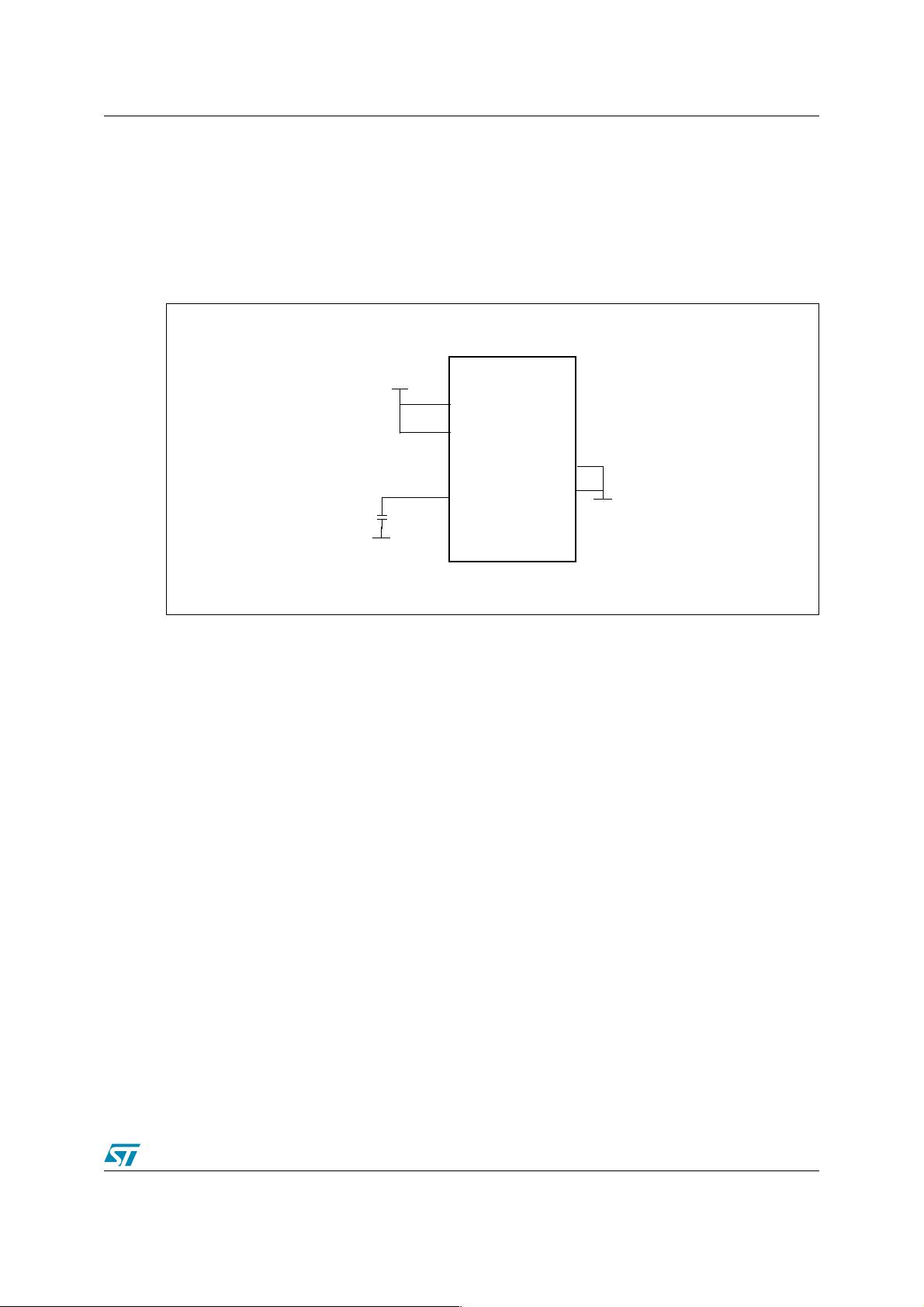
1.1 Power supply pins
The following figure indicates the recommended configuration for the power supply pins:
Figure 1. STR73x power supply pins
● V
● V
pin: is the 5V main power supply pin.
DD
pin: must be connected to a capacitor of at least 100nF (ceramic) in order to
18
guarantee the stability of the 1.8V supply to the core.
1.2 Internal regulators
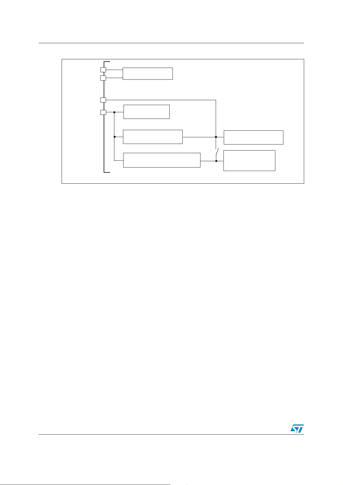
The following figure provides a schematic view of the power management block of the STR73x.
VSS
5V
100nF
V
AV
V
DD
DD
18
STR73x
AV
SS
VSS
V
SS
3/12
Page 4
1 Power supply AN2202
Figure 2. Power management block
AV
AV
DD
SS
V
18
V
DD
A/D converter
Memory and I/Os
Main Voltage Regulator
Low Power Voltage Regulator
V18
Note*
V18
Core and Peripherals
Peripherals active
in LPWFI mode
Note: * Disconnected in LPWFI mode.
Main Voltage Regulator (MVR)
In normal operation, the Main Voltage Regulator (MVR) provides the 1.8V supply.
The MVR can be switched off when entering a low power mode (refer to Section 3)
When the MVR is switched off, the Low Power Voltage Regulator (LPVR) can provide a power
supply of about 1.8V (+/- 10%).
Note: 1 The MVR has a static power consumption of 3.97 mA typ at 25°C.
2 When the MVR is switched off, The PLL is automatically disabled (PLL off) and the maximum
allowed operating frequency is 2 MHz, this is due to the limitation imposed by the LPVR which
is not able to generate sufficient current to operate in run mode.
1.2.1 Low Power Voltage Regulator (LPVR)
The Low Power Voltage Regulator (LPVR) is used when the MCU is in low-power mode and the
main voltage regulator has been switched off. It has a different design from the main voltage
regulator and generates a stabilized and thermally-compensated voltage in the range of 1.8V
(+/- 10%), its output current is not generally sufficient for the device to run in normal operation.
4/12
Page 5

AN2202 2 Clock management
2 Clock management
The following figure provides an overview of the clock management block of the STR73x:
Figure 3. Clock management block
XTAL1
XTAL2
V
BIAS
Main
Oscillator
RC
Back Up
Oscillator
f
Osc
f
RC
WAKE Up Timer
CMU
PRESCALER
f
CLK1
1/2
f
CLK2
PRCCU
1/16
PLL
f
EXT
f
MCLK
Legend:
f
= to CPU and peripherals
MCLK
f
= from CMU, to PRCCU
CLK1
f
= before PLL
CLK2
2.1 Clock configuration & power management
Different clock configurations are provided by the STR73x MCU offering the means to optimize
the power consumption in the device, the main features are:
● Individual peripheral clock disabling.
● Up to three low power system clocks: CLK2, CLK2/16 and the PLL Free running mode
clock (refer to the PRCCU section in the STR73x reference manual for details on the PLL
free running mode).
2.2 Disabling peripherals clocks
The peripheral clock managing registers (PCGR0 and PCGR1 of the configuration registers)
allows each module clock of the device to be switched on/off individually. Refer to the
Configuration Registers section in the STR73x reference manual.
Note: 1 PLL is automatically disabled when:
- The Main Voltage Regulator (MVR) is stopped
- Entering LPWFI, STOP or HALT low power modes
- When PRCCU_PLLCR DX[2:0] bits are set to ‘111’ and FREEN bit is reset
2 When not using the RC clock, you can disable it by setting bit RCHSE and/or RCSS in the
PCU_CTRL register.
5/12
Page 6

3 STR73x low power modes AN2202
3 STR73x low power modes
3.1 Low power mode characteristics
The STR73x low power modes are summarized in the following table:
Table 1. STR73x low power modes
Power mode Description
SLOW
Wait For Interrupt (WFI)
Low Power WFI
(LPWFI)
STOP
HALT
- PLL off and MCLK1) = CLK2 or CLK2/16
- Free running PLL
- Core stopped (MCLK off)
- Wake-up by interrupts acknowledged by the interrupt controller (EIC)
- MCU state retained (context restored after wakeup)
- Core stopped
- Peripherals running at slow clock: CLK2/16
- Wake-up by interrupts acknowledged by the EIC
- MCU state retained
- Core and peripherals stopped (MCLK off)
- Wake-up by the configured external wake-up lines
- MCU state retained
- Oscillators stopped
- Wake up is only possible by means of external reset (H/W pin) or LVD reset
(Power-on) as the RC oscillator is off
(MCLK off)
Note: 1 Refer to Figure 3 for the definition of the various clocks (MCLK, CLK1, CLK2, CLK2/16, RC).
3.2 Guidelines for entering/exiting low power modes
3.2.1 SLOW mode
To enter SLOW mode, MCLK must be configured as CLK2 or CLK2/16.
When using these clock settings, the PLL can be disabled by writing ‘111’ in the DX[2:0] bits in
the PRCCU_PLLCR register.
Table 2. SLOW mode selection
MCLK
CLK2 0 1 0
CLK2/16 x 0 0
Free running PLL 1 1 1
Note: 1 CSU_CKSEL is bit 0 in register PRCCU_CFR.
2 CK2_16 is bit 3 in register PRCCU_CFR
6/12
CSU_CKSEL
1)
CK2_16
2)
FREEN
3)
Page 7

AN2202 3 STR73x low power modes
3 FREEN is bit 7 in register PRCCU_PLLCR, in the same register the DX(2:0) must be all sets in
order to provide the PLL slow frequency.
3.2.2 WFI mode
To enter WFI mode, you must clear the WFI bit in the PRCCU_SMR register.
To wakeup from WFI mode an interrupt request must be acknowledged by the EIC.
3.2.3 LPWFI mode
To enter LPWFI mode you have to:
1. Select the clock which will be used by peripherals during LPWFI: RC or external oscillator
with the CMU (CKSEL0 bit in the CMU_CTRL register), this clock can be set as running
low (with RCFR bit in CMU_CTRL register)
2. During the LPWFI, the clock used will be divided by 16: CLK2/16 (WFI_CKSEL bit of the
PRCCU_CCR register)
3. Select LPWFI mode by setting the LPOWFI bit in the PRCCU_CCR register.
4. Write 0 in the WFI bit of the PRCCU_SMR register to enter LPWFI mode
Like WFI mode, to wakeup from LPWFI mode an interrupt request must be acknowledged by
the EIC.
To further reduce MCU power consumption in LPWFI mode you can:
● Stop the Main voltage regulator (MVR) by setting bit VRLPW in the PRCCU_VRCTR
register.
● In LPWFI, the FLASH module should enter Power Down mode by setting the LPS bit of
FLASH CR0 register status.
Note: 1 After exit from LPWFI mode, the Flash and the main voltage regulator are re-enabled
automatically if they were switched off during the low power mode.
2 After wakeup, the original MCLK clock configuration must be restored by software.
3.2.4 STOP mode
To enter STOP mode you have to:
1. Configure at least one external wake-up line or WUT to wake-up the MCU from STOP
mode. (Refer to the WIU & WUT section in the STR73x reference manual)
2. Reset the STOP bit in register WIU_CTRL and the STOP_I bit in the PRCCU_CFR
register.
3. To enter STOP mode, write the sequence 1, 0, 1 to the STOP bit in the WIU_CTRL
register.
4. In order to avoid executing any valid instructions after a STOP bit setting sequence and
before entering STOP mode, it is mandatory to execute a few (at least 6) dummy
instructions after the STOP bit setting sequence.
5. To be sure that STOP mode was really entered, immediately after the end of the STOP bit
setting sequence (including the dummy instructions), poll the PRCCU STOP_I flag bit and
the STOP bit (WIU_CTRL register). If the STOP bit setting sequence has been correctly
executed, these bits must be STOP_I = 1 and STOP = 0. If it is not the case you must
restart all the sequence from the beginning.
6. When exiting STOP mode, clear the pending wake up interrupt line (WIU_PR register).
7/12
Page 8

3 STR73x low power modes AN2202
7. On wake-up from STOP mode, the CMU automatically selects the 2MHz RC-Oscillator
clock as input clock to the PRCCU.
To further reduce power consumption during STOP mode, it is possible to:
● Disable the main voltage regulator by writing ‘1’ in bit VRLPW in the PRCCU_VRCTR
register.
● Minimize the low power voltage regulator current capability by setting the bit 0 and 1 of the
system configuration register 1 (LPVRCC(1:0)).
Note: After exit from STOP mode, the Flash and the main voltage regulator are re-enabled
automatically if they were switched off during the STOP mode
3.2.5 HALT mode
The HALT sequence is initiated with the following procedure:
● set the EN_HALT bit in the PRCCU_SMR and clear the SRESEN bit in the PRCCU_CCR
● then set the HALT bit in the PRCCU_CCR.
Caution: Wake-up from HALT mode is only possible by means of an external or LVD reset.
Note: Minimize the low power voltage regulator current capability by setting the bit 0 and 1 of the
system configuration register 1 (LPVRCC(1:0)).
8/12
Page 9

AN2202 4 Example application
4 Example application
4.1 Example hardware
Figure 4 shows an example schematic for using the STR73x power management features.
Figure 4. Example application schematic
STR73x
V
=5V
DD1
A
100nF
V
DD
V
18
1K
100nF
V
10K
DD2
V
DD2
=5V
=5V
100nF
WUP6
nRSTIN
VBIAS
P5.8
P4.6
XTAL1
XTAL2
1.3M
LED1
4MHz
V
100
DD2
=5V
10K
V
=5V
DD2
10nF
15pF15pF
Note: 1 WUP6 is configured as an external interrupt pin, it is used to wake up the MCU from WFI,
LPWFI or STOP mode.
2 P4.6 is used to indicate that the core is running (GPIO toggling) during RUN/SLOW modes.
3 P5.8 is used to enter HALT or SLOW modes. It is used also to exit from SLOW_RC mode.
4.2 Example software
A program is provided with this application note for using the different low power modes, it
includes the following source files:
9/12
Page 10

4 Example application AN2202
Table 3. Software files
File Description
main.c Example software for using different low power modes
73x_it.c Interrupt service routines
The following routines are implemented in the main.c file:
Table 4. Low power Mode routines
Modes Mode configuration/ Options during the selected low power mode
RUN_Mode - RC oscillator off, RTC on, TIM3 on and flash on.
RUN_ALLON_Mode - ALL peripheral on.
SLOW_Mode - CLK2, CLK2_16 or free running PLL selectable
SLOW_RC_Mode - CLK (CLK2 with div2 disabled)
WFI_Mode - Value of MCLK can be modified
- Main Voltage Regulator (MVR) stopped (software selectable)
LPWFI_Mode
- Flash in power down or in low power (software selectable)
- WUP6 pin configured as external rising edge interrupt
- RC running high clock is used (software selectable)
LPWFI_RC_Mode
STOP_Mode
STOP_WUT_Mode
HALT_Mode - Device halted.
- Main Voltage Regulator (MVR) stopped (software selectable)
- Flash in power down or in low power (software selectable)
- WUP6 pin configured as external rising edge interrupt
- Flash in power down
- Main Voltage Regulator (MVR) stopped (software selectable)
- Wakeup by WUP6 pin configured as rising edge wakeup
- Flash in power down
- Main Voltage Regulator (MVR) stopped (software selectable)
- Wakeup by the WUT configured as rising edge. Wakeup after 10 second delay
Note: To select a low power mode, you have to uncomment the corresponding define code ‘#define
xxx_Mode and rebuild the main.c file.
4.3 Power consumption measurements
All consumption measurements are listed in the STR73x datasheet.
10/12
Page 11

AN2202 5 Revision history
5 Revision history
Date Revision Changes
05-Jan-2006 1 Initial release
12-09-2006 2
Figure 4 on page 9:
Section 3.2.1 on page 6: SLOW mode updated.
Section 3.2.4 on page 7: STOP mode updated.
Table 4 on page 10:
Example application schematic updated.
Low power Mode routines updated.
11/12
Page 12

5 Revision history AN2202
Please Read Carefully:
Information in this document is provided solely in connection with ST products. STMicroelectronics NV and its subsidiaries (“ST”) reserve the
right to make changes, corrections, modifications or improvements, to this document, and the products and services described herein at any
time, without notice.
All ST products are sold pursuant to ST’s terms and conditions of sale.
Purchasers are solely responsible for the choice, selection and use of the ST products and services described herein, and ST assumes no
liability whatsoever relating to the choice, selection or use of the ST products and services described herein.
No license, express or implied, by estoppel or otherwise, to any intellectual property rights is granted under this document. If any part of this
document refers to any third party products or services it shall not be deemed a license grant by ST for the use of such third party products
or services, or any intellectual property contained therein or considered as a warranty covering the use in any manner whatsoever of such
third party products or services or any intellectual property contained therein.
UNLESS OTHERWISE SET FORTH IN ST’S TERMS AND CONDITIONS OF SALE ST DISCLAIMS ANY EXPRESS OR IMPLIED
WARRANTY WITH RESPECT TO THE USE AND/OR SALE OF ST PRODUCTS INCLUDING WITHOUT LIMITATION IMPLIED
WARRANTIES OF MERCHANTABILITY, FITNESS FOR A PARTICULAR PURPOSE (AND THEIR EQUIVALENTS UNDER THE LAWS
OF ANY JURISDICTION), OR INFRINGEMENT OF ANY PATENT, COPYRIGHT OR OTHER INTELLECTUAL PROPERTY RIGHT.
UNLESS EXPRESSLY APPROVED IN WRITING BY AN AUTHORIZED ST REPRESENTATIVE, ST PRODUCTS ARE NOT
RECOMMENDED, AUTHORIZED OR WARRANTED FOR USE IN MILITARY, AIR CRAFT, SPACE, LIFE SAVING, OR LIFE SUSTAINING
APPLICATIONS, NOR IN PRODUCTS OR SYSTEMS WHERE FAILURE OR MALFUNCTION MAY RESULT IN PERSONAL INJURY,
DEATH, OR SEVERE PROPERTY OR ENVIRONMENTAL DAMAGE. ST PRODUCTS WHICH ARE NOT SPECIFIED AS "AUTOMOTIVE
GRADE" MAY ONLY BE USED IN AUTOMOTIVE APPLICATIONS AT USER’S OWN RISK.
Resale of ST products with provisions different from the statements and/or technical features set forth in this document shall immediately void
any warranty granted by ST for the ST product or service described herein and shall not create or extend in any manner whatsoever, any
liability of ST.
ST and the ST logo are trademarks or registered trademarks of ST in various countries.
Information in this document supersedes and replaces all information previously supplied.
The ST logo is a registered trademark of STMicroelectronics. All other names are the property of their respective owners.
© 2006 STMicroelectronics - All rights reserved
STMicroelectronics group of companies
Australia - Belgium - Brazil - Canada - China - Czech Republic - Finland - France - Germany - Hong Kong - India - Israel - Italy - Japan -
Malaysia - Malta - Morocco - Singapore - Spain - Sweden - Switzerland - United Kingdom - United States of America
www.st.com
12/12
 Loading...