

Page 1

AN2165
Application note
ST10F27X Firmware Development
Getting Started with Keil µVision ST10 Toolchain
Introduction
This document provides an introduction to the Keil µVision toolchain (version 2) for the ST10F27x product
family. It summarizes the different steps needed to configure the Keil development toolset, to build and to
debug an application.
Although this application note cannot show all the topics relevant to the Keil tool, it demonstrates the first
steps necessary to get started with the compiler/debugger.
Two very simple software examples are supplied with this application note. The first is a small application
displaying a message on the toolset serial window. This example is used to show the required steps to
create a project, build and debug it. The second example illustrates how to use interrupts and the Logic
Analyser feature.
The application source files are provided within an archived file. This file can be unpacked into any
directory.
June 2006 Rev 1 1/18
www.st.com
18
Page 2

AN2165
Contents
1 Keil ST10 toolchain . . . . . . . . . . . . . . . . . . . . . . . . . . . . . . . . . . . . . . . . . . . . 3
1.1 Starting Keil µVision Integrated Development Environment (IDE) . . . . . . . . . 3
1.2 Creating a new project . . . . . . . . . . . . . . . . . . . . . . . . . . . . . . . . . . . . . . . . . . 4
1.3 Adding files to the project . . . . . . . . . . . . . . . . . . . . . . . . . . . . . . . . . . . . . . . . 6
1.3.1 Adding existing files . . . . . . . . . . . . . . . . . . . . . . . . . . . . . . . . . . . . . . . . . . . . . 6
1.3.2 Adding new files . . . . . . . . . . . . . . . . . . . . . . . . . . . . . . . . . . . . . . . . . . . . . . . 6
1.4 Setting build options . . . . . . . . . . . . . . . . . . . . . . . . . . . . . . . . . . . . . . . . . . . . 8
1.5 Building the application . . . . . . . . . . . . . . . . . . . . . . . . . . . . . . . . . . . . . . . . 10
1.6 Debugging the application with Keil µVision debugger . . . . . . . . . . . . . . . . . 11
2 Application example: interrupt handling . . . . . . . . . . . . . . . . . . . . . . . . . . 14
2.1 Debug operation . . . . . . . . . . . . . . . . . . . . . . . . . . . . . . . . . . . . . . . . . . . . . . 14
2.2 Logic analyser use . . . . . . . . . . . . . . . . . . . . . . . . . . . . . . . . . . . . . . . . . . . . 14
3 Revision history . . . . . . . . . . . . . . . . . . . . . . . . . . . . . . . . . . . . . . . . . . . . . . 17
2/18
Page 3
AN2165 Keil ST10 toolchain
1 Keil ST10 toolchain
In order to start a project with keil toolchain, we need to perform the following steps:
● Edit / Project management: in this part, projects are created and maintained, project
source files are edited etc.
● Build: here, a makefile (created by the Edit part) is used to invoke the needed toolchain
components, resulting in an executable file.
● Debug: in this part, the executable file is used to debug the project.
Neither the toolset installation nor the license management are described in this application
note. This section assumes that Keil is already installed on the development host.
For more details on Keil installation and licenses’ management, refer to Keil documentation.
This section describes the steps required for creating, building and debugging an ST10F27x
application using the Keil toolchain.
1.1 Starting Keil µVision Integrated Development Environment (IDE)
To select Keil toolchain:
● Select Start -> Programs ->Keil µVision.
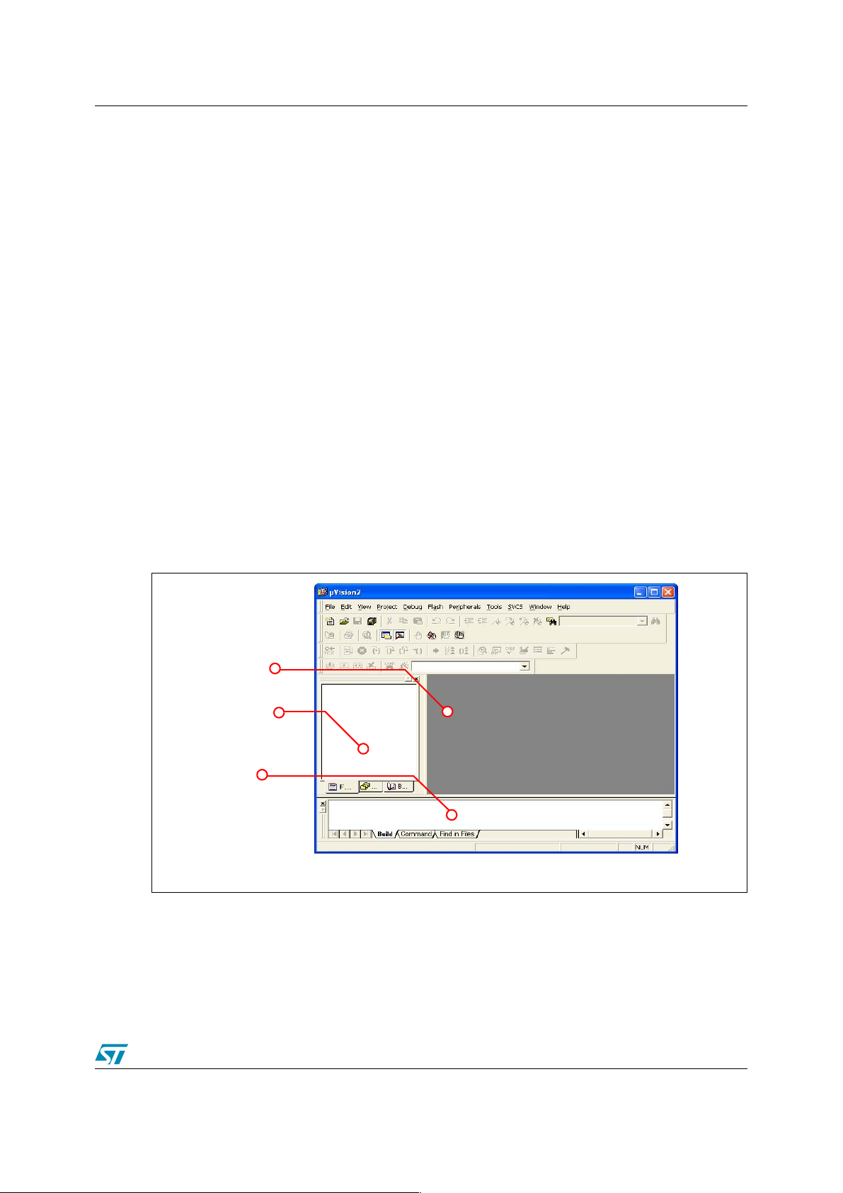
Keil µVision starts and the following window appears:
Files Window
Project Window
Output Window
The Files window is used to edit source files. The project window contains several tabs for
viewing informations about projects and other files. The output window contains several tabs to
display results of EDE operations as compiles and builds.
For further information about the windows contents, refer to the Keil documentation.
3/18
Page 4
Keil ST10 toolchain AN2165
1.2 Creating a new project
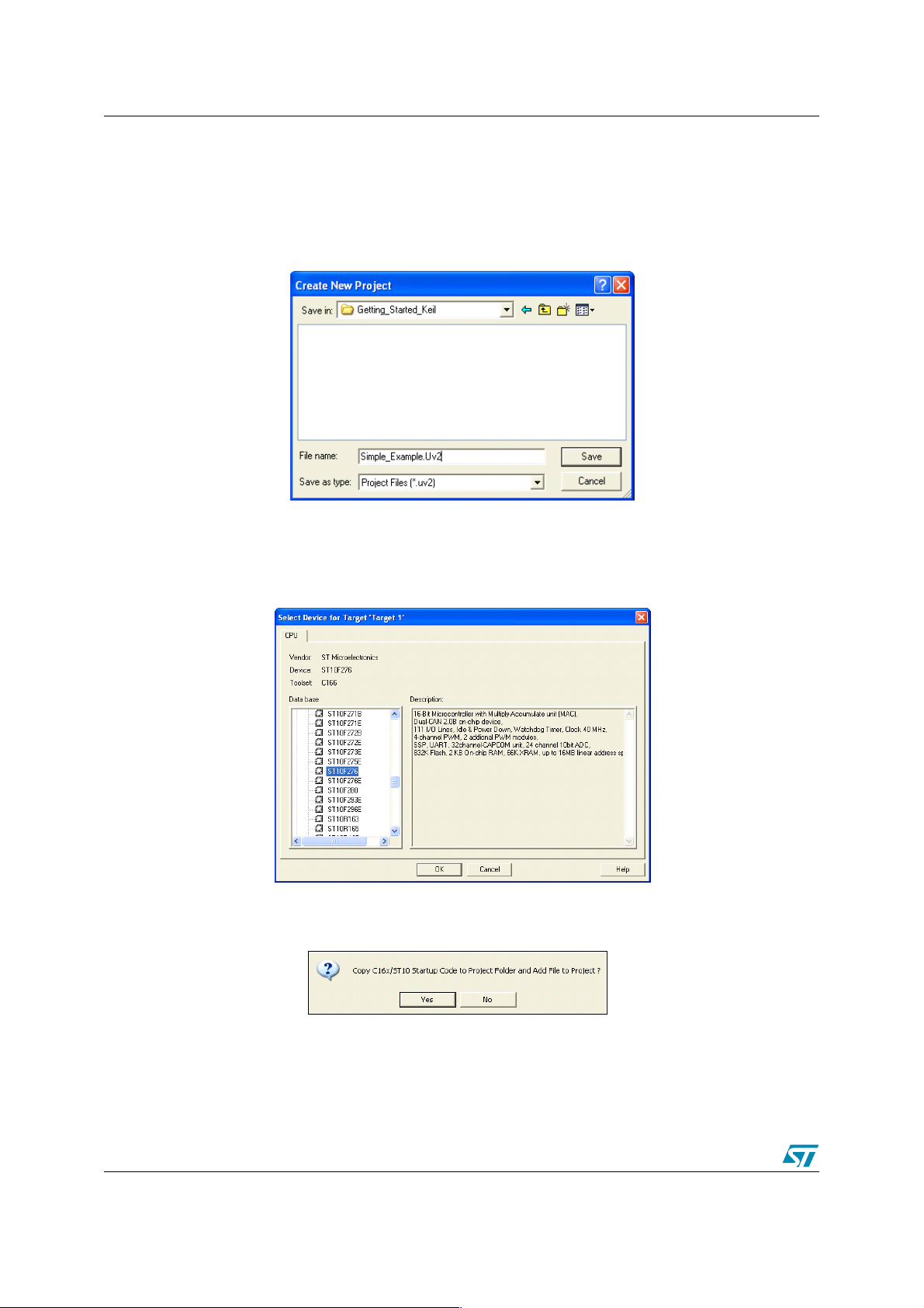
● Select New project from the Project menu. This opens a Window dialog that asks you for
the new project file name (see the figure below)
● Use the Browse button to select a working directory.
● Enter ’Simple_Example’ as the project space name in the Filename field.
● Click Save to confirm your entry.
● The Select Device for Target ’Target1’ window appears automatically allowing you to
select a CPU for your project. This window shows the µVision device database. Select the
ST10F27x MCU you plan to use. In this example, the ST10F276 microcontroller is used.
● Click OK to confirm your entry.
The following appears automatically:
● Click Yes to confirm.
This window asks you to add the startup code to the project.
4/18
Page 5
AN2165 Keil ST10 toolchain
An ST10 program requires a CPU start up initialization code that is run just after a device reset.
This start up code is used to set up the configuration of your hardware design and is written in
assembly.
This file can be modified to match your hardware configuration.
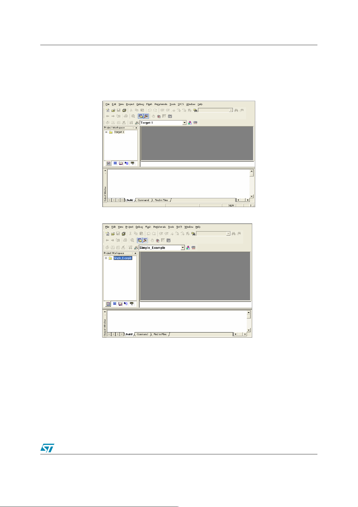
The following figure appears:
● You can rename Target1 in the Project Window ’Simple_Example’ to improve readibility.
A project can have more than one Target. Creating another Target for a project means creating
a project with the same source files. This is useful if you need a Target for testing and another
Target for a release version of your application. If you also want to debug your application using
two different configurations, you can use two Targets and each Target allows individual tool
settings within the same project files.
To add a new target, right-click on the project and select Manage components. From the
window that appears, select Project components tab and click on the New button.
5/18
Page 6
Keil ST10 toolchain AN2165
1.3 Adding files to the project
There are two ways to add source files to the project. Either the source file already exists in the
working directory, in which case proceed as described in the Section 1.3.1, or new source files
containing your own code are added as described in the Section 1.3.2.
1.3.1 Adding existing files
● Copy in your working directory the ’main.c’ file located in the folder ’Example1’ provided
with this application note.
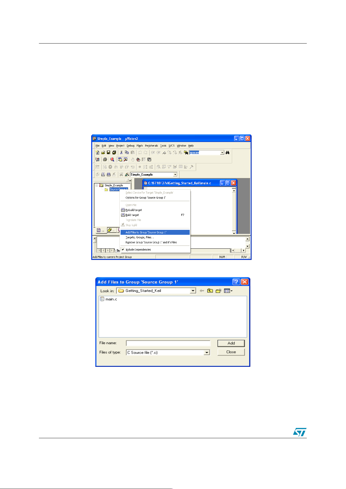
● Right-click on Source Group 1 and select Add Files to Source Group 1
The following window appears:
– Select ’main.c’ and click Add to confirm.
1.3.2 Adding new files
● You may create a new source file with the menu option File - New. This opens an empty
editor window where you can enter your source code.
6/18
Page 7

AN2165 Keil ST10 toolchain
● Save the created file as ’main.c’.
● Right-click on Source Group 1 and select Add Files to Source Group 1
The following window appears:
7/18
Page 8

Keil ST10 toolchain AN2165
– Select ’main.c’ and click Add to confirm.
In this project, there is only one source file. If the application requires more than one source file
and header file, you have to include them in the project in the same way as ’main.c ’ file.
1.4 Setting build options
Before building your project, you should specify compiler and linker options. This section will
present the most important options to be set.
● Right click on ’Simple_Example’
● Select Options for Target ’Simple_Example’
The Options for Target ’Simple_Example’ dialog appears.
This dialog contains several tabs to configure the project parameters.
1. Device
On the Device tab, you can select the ST10F27x device you want to use as mentioned in
Section 1.2.
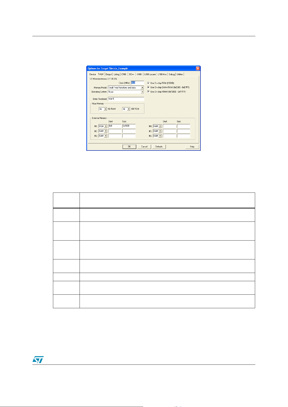
2. Target
On the Target tab, you need to:
8/18
Page 9
AN2165 Keil ST10 toolchain
– Specify the ST10F276 operating CPU frequency, for example 64Mhz.
– Fill the External Memory field with your external memory device address on the
external bus. It is not mandatory to enter the location of the internal memory.
– Select the memory model. The memory model defines the default variable and
function location and their default pointer size. The right selection depends on the
application and impacts the compiler efficiency.
There are 7 memory models: Tiny, Small, Compact, Hcompact, Medium, Large,
Hlarge. The Small memory model is used by default.
The memory models with their characteristics are represented in the following table:
Memory
models
Characteristics
Tiny
Small
Medium
Compact
Large This models treats both function calls and data objects as FAR.
HLarge
Hcompact
All code and data must be within the first 64K. All function calls must be within the same
segment.
Code size is limited to 64K and data is limited to 16K for variables and 16K for constants.
Using the far and huge keywords in data declarations can expand the overall data size to
any size.
Code size is unlimited and data is limited to 16K of variables and 16K of constants. Using
the far and huge keywords in data declarations can expand the overall data size to any
size.
This model is the opposite of Medium. It is useful for programs with small amounts of code
but a large data group.
This model is only available with MOD167. HLarge is the same as Large but the default for
variable declarations is HUGE.
This model is only available with MOD167. Hcompact is the same as Compact but the
default for variable declarations is HUGE.
For more details about memory models and choice criteria, please refer to Keil
documentation.
3. Output
9/18
Page 10

Keil ST10 toolchain AN2165
In this tab, you can select the format of your output file. For example, for HEX format,
select Create HEX File.
For more details about Tool options, please refer to Keil documentation.
1.5 Building the application
The project has been configured. You can now build it by selecting Build Target
µVision will display errors and warning messages in the Output Window-Build page. A
double-click on a message line opens the source file on the correct location in the µVision
editor window.
When building the application successfully, many files will be generated automatically and
placed in the working directory.
10/18
Page 11

AN2165 Keil ST10 toolchain
1.6 Debugging the application with Keil µVision debugger
Keil µVision debugger provides a high level interface between the user and a program running
in the target system (execution environment).
Debugging the application requires that you have successfully compiled and built your
application.
The µVision debugger offers two operating modes:
● Simulator : allows the configuration of the µVision debugger to simulate most features of
the ST10F27x family without actually having target hardware. You can test and debug
your embedded application before the hardware is ready.
● Debug on a hardware target: using for example Monitor 166 which is a program that
resides in the external RAM memory of your target hardware. In this case, Keil µVision
debugger runs on a PC computer and is connected to the ST10F27x target microcontroller
via RS232 interface.
The monitor requires an external RAM memory to run. This RAM memory must be selected at
reset.
When using this mode, the following requirements should be taken into account:
● External RAM chip select should be active
● Enter the bootstrap loader mode by forcing P0L.4 to 0 at reset
● The Debug tab in Options for Target ’Simple_Example’ dialog configures the µVision
debugger.
The simulator is used in this example by simply selecting Use Simulator.
This is illustrated in the following figure:
Select Debug -> Start/Stop Debug session from the menu toolbar in order to start debugging
the application.
11/18
Page 12

Keil ST10 toolchain AN2165
µVision provides more than one serial window for serial input and output. Select View ->
Serial Window #
Select Debug -> go from the menu toolbar:
12/18
Page 13

AN2165 Keil ST10 toolchain
If everything is working properly, the following message appears on the serial window in an
infinite loop
You can use breakpoints to run the application step by step. The memory and register contents
can also be displayed.
For more details about µVision debugging features, refer to the Keil µVision documentation.
13/18
Page 14

Application example: interrupt handling AN2165
2 Application example: interrupt handling
This section describes a simple ST10F27x software example making use of the interrupts. The
application uses Timers’ overflow interrupts to generate two square signals with different
frequencies on two standard port pins: P2.0 & P2.1.
The project contains 3 source files:
● Timer.c: It contains c source code for the following project routines
– Configure_GPT1_Timer_2(): In this routine, GPT1 Timer 2 is set up to operate in
Timer mode and is configured to generate an interrupt every 1.678 seconds.
– Configure_GPT1_Timer_3(): In this routine, GPT1 Timer 3 is set up to operate in
Timer mode and is configured to generate an interrupt every 104.8 milliseconds.
– Timer 2 and Timer 3 interrupts’ definitions: Timer 2 interrupt is toggling P2.0 while
Timer 3 interrupt is toggling P2.1.
● Timer.h: It contains Timer.c routines prototypes.
● main.c: It uses the routines described in Timer.c in order to start the two timer overflow
interrupts.
Timings suppose that the chip is operating at a frequency of 40 Mhz.
The environment has been setup as described in the first chapter.
For more details about the timers’ functionalities, their registers and interrupts’ handling, refer to
the ST10F27x user’s manual.
2.1 Debug operation
After successfully building the program:
● Select Debug -> Start / Stop Debug Session from the toolbar menu.
Port 2 output signals can be displayed using the Logic Analyser feature provided by Keil. This
feature is available only on simulation mode.
In order to view the port 2 content, select Peripherals -> IO Ports -> Port 2 from the toolbar
menu.
2.2 Logic analyser use
● Select View -> Logic Analyser Window from the toolbar menu of the debug window.
● Select Debug -> Logic Analyser from the toolbar menu
● Enter the variable that you want to visualize: Port 2 pin 0 and Port 2 pin1.
● Precise the Mask to indicate if the signal corresponds to P2.0 or P2.1.
14/18
Page 15

AN2165 Application example: interrupt handling
● Choose a color for each output signal. For example, choose the green color for P2.0 output
signal and the blue color for P2.1 output signal.
Delete an existing
variable
ADD a new
variable
● Click Close to confirm your entries.
● Select Debug -> Go from the toolbar menu.
15/18
Page 16
Application example: interrupt handling AN2165
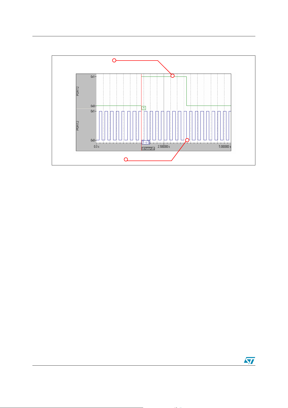
The figure below shows the behavior of the port 2 pins 0 &1 and the GPT1 Timer 2 & Timer 3
overflow interrupts.
PIN P2.0 OUTPUT (GPT1 TIMER 2 OVERFLOW INTERRUPT)
PIN P2.1 OUTPUT (GPT1 TIMER 3 OVERFLOW INTERRUPT)
The example source code is located in the ’Example2’ folder provided with this application note.
For more details about the timers’ functionalities, their registers and interrupts’ handling, refer to
the ST10F27x user’s manual.
16/18
Page 17

AN2165 Revision history
3 Revision history
Table 1. Document revision history
Date Revision Changes
30-Jun-2006 1 Initial release.
17/18
Page 18

Revision history AN2165
r
Please Read Carefully:
Information in this document is provided solely in connection with ST products. STMicroelectronics NV and its subsidiaries (“ST”) reserve the right to make changes, corrections,
modifications or improvements, to this document, and the products and services described herein at any time, without notice.
All ST products are sold pursuant to ST’s terms and conditions of sale.
Purchasers are solely responsible for the choice, selection and use of the ST products and services described herein, and ST assumes no liability whatsoever relating to the
choice, selection or use of the ST products and services described herein.
No license, express or implied, by estoppel or otherwise, to any intellectual property rights is granted under this document. If any part of this document refers to any third party
products or services it shall not be deemed a license grant by ST for the use of such third party products or services, or any intellectual property contained therein or considered
as a warranty covering the use in any manner whatsoever of such third party products or services or any intellectual property contained therein.
UNLESS OTHERWISE SET FORTH IN ST’S TERMS AND CONDITIONS OF SALE ST DISCLAIMS ANY EXPRESS OR IMPLIED WARRANTY WITH RESPECT TO THE
USE AND/OR SALE OF ST PRODUCTS INCLUDING WITHOUT LIMITATION IMPLIED WARRANTIES OF MERCHANTABILITY, FITNESS FOR A PARTICULAR
PURPOSE (AND THEIR EQUIVALENTS UNDER THE LAWS OF ANY JURISDICTION), OR INFRINGEMENT OF ANY PATENT, COPYRIGHT OR OTHER INTELLECTUAL
PROPERTY RIGHT.
UNLESS EXPRESSLY APPROVED IN WRITING BY AN AUTHORIZE REPRESENTATIVE OF ST, ST PRODUCTS ARE NOT DESIGNED, AUTHORIZED OR WARRANTED
FOR USE IN MILITARY, AIR CRAFT, SPACE, LIFE SAVING, OR LIFE SUSTAINING APPLICATIONS, NOR IN PRODUCTS OR SYSTEMS, WHERE FAILURE OR
MALFUNCTION MAY RESULT IN PERSONAL INJURY, DEATH, OR SEVERE PROPERTY OR ENVIRONMENTAL DAMAGE.
Resale of ST products with provisions different from the statements and/or technical features set forth in this document shall immediately void any warranty granted by ST fo
the ST product or service described herein and shall not create or extend in any manner whatsoever, any liability of ST.
ST and the ST logo are trademarks or registered trademarks of ST in various countries.
Information in this document supersedes and replaces all information previously supplied.
The ST logo is a registered trademark of STMicroelectronics. All other names are the property of their respective owners.
© 2006 STMicroelectronics - All rights reserved
STMicroelectronics group of companies
Australia - Belgium - Brazil - Canada - China - Czech Republic - Finland - France - Germany - Hong Kong - India - Israel - Italy - Japan - Malaysia - Malta - Morocco - Singapore
- Spain - Sweden - Switzerland - United Kingdom - United States of America
www.st.com
18/18
 Loading...