

Page 1
AN2159
Application note
SPI protocol for STPM01/STPM10 metering devices
Introduction
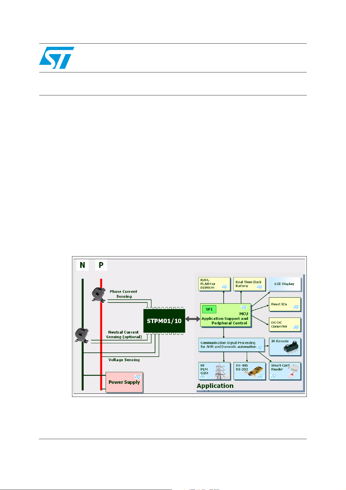
The STPM01 and STPM10 devices are energy meter ASSPs (Application Specific Standard
Products) designed to address a wide range of electricity metering requirements thanks to
their built-in functionalities as signal conditioning, signal processing, data conversion,
input/output signals and voltage reference.
STPM10 is dedicated for peripheral use only in microcontroller based applications, while
STPM01 is able to work as a peripheral but also as a standalone device, since it can
permanently store configuration and calibration data.
Both the devices have an SPI port to write configuration parameters and read all the
information on the line energy from their internal registers.
Measured data (like active, reactive and apparent energy, V
voltage and current, line frequency, device status etc.) should be read by the microcontroller
at a fixed time interval to be further processed.
This application note describes the SPI protocol to read measured data from STPM01 and
STPM10 in a single-phase energy meter and how these readings should be processed by
the application.
Figure 1. STPMxx based application block diagram
RMS
, I
, instantaneous
RMS
July 2010 Doc ID 11400 Rev 3 1/23
www.st.com
Page 2

Contents AN2159
Contents
1 Devices overview . . . . . . . . . . . . . . . . . . . . . . . . . . . . . . . . . . . . . . . . . . . 3
1.1 STPM01 . . . . . . . . . . . . . . . . . . . . . . . . . . . . . . . . . . . . . . . . . . . . . . . . . . . 3
1.2 STPM10 . . . . . . . . . . . . . . . . . . . . . . . . . . . . . . . . . . . . . . . . . . . . . . . . . . . 3
2 SPI module description . . . . . . . . . . . . . . . . . . . . . . . . . . . . . . . . . . . . . . 4
2.1 Connection to microcontroller . . . . . . . . . . . . . . . . . . . . . . . . . . . . . . . . . . . 4
3 SPI interface timings . . . . . . . . . . . . . . . . . . . . . . . . . . . . . . . . . . . . . . . . . 6
4 SPI operations . . . . . . . . . . . . . . . . . . . . . . . . . . . . . . . . . . . . . . . . . . . . . . 7
4.1 Remote reset request . . . . . . . . . . . . . . . . . . . . . . . . . . . . . . . . . . . . . . . . . 7
4.2 Data registers writing . . . . . . . . . . . . . . . . . . . . . . . . . . . . . . . . . . . . . . . . . 7
4.3 Data registers permanent writing (STPM01 only) . . . . . . . . . . . . . . . . . . 10
4.4 Reading data registers . . . . . . . . . . . . . . . . . . . . . . . . . . . . . . . . . . . . . . . 10
5 Data processing . . . . . . . . . . . . . . . . . . . . . . . . . . . . . . . . . . . . . . . . . . . 13
5.1 Reading process . . . . . . . . . . . . . . . . . . . . . . . . . . . . . . . . . . . . . . . . . . . 13
5.1.1 Data register assembling example . . . . . . . . . . . . . . . . . . . . . . . . . . . . . 14
5.2 Parity check . . . . . . . . . . . . . . . . . . . . . . . . . . . . . . . . . . . . . . . . . . . . . . . 14
5.2.1 Parity check example . . . . . . . . . . . . . . . . . . . . . . . . . . . . . . . . . . . . . . . 15
5.3 Unpacking data . . . . . . . . . . . . . . . . . . . . . . . . . . . . . . . . . . . . . . . . . . . . 15
6 Converting readings into measured values . . . . . . . . . . . . . . . . . . . . . 16
6.1 Energies . . . . . . . . . . . . . . . . . . . . . . . . . . . . . . . . . . . . . . . . . . . . . . . . . . 16
6.2 Other values . . . . . . . . . . . . . . . . . . . . . . . . . . . . . . . . . . . . . . . . . . . . . . . 18
7 Revision history . . . . . . . . . . . . . . . . . . . . . . . . . . . . . . . . . . . . . . . . . . . 22
2/23 Doc ID 11400 Rev 3
Page 3

AN2159 Devices overview
1 Devices overview
1.1 STPM01
The STPM01 is an ASSP designed for effective measurement of active, reactive and
apparent energy in a power line system using Rogowski coil, current transformer and shunt
sensors. This device can be implemented as a single chip in single phase energy meters or
as a peripheral in microcontroller based meter.
The STPM01 consists, essentially, of two parts: the analog part and the digital part. The
former, is composed by preamplifier and 1
voltage reference, low drop voltage regulator, the latter by system control, oscillator, hard
wired DSP and SPI interface.
There is also an OTP block, which is controlled through the SPI by means of a dedicated
command set. The configured bits are used for testing, configuration and calibration
purpose.
The DSP unit computes active, reactive and apparent energy, RMS and instantaneous
values of voltage and current. The results of computation are available as pulse frequency
and states on the digital outputs of the device or into the internal data registers, which can
be read from the device by means of SPI.
For more details on the device please refer to datasheet.
1.2 STPM10
The STPM10 is designed for effective measurement of active, reactive and apparent energy
in a power line system using Current Transformer or Shunt sensors. This device is intended
to be a peripheral measurement device in a microcontroller based meter.
The STPM10 consists of an analog part and a digital part. The former, is composed by
preamplifier and 1
voltage regulator, the latter by system control, oscillator, hard wired DSP and SPI interface.
st
order Δ ∑ A/D converter blocks, band gap
st
order Δ ∑ A/D converter blocks, Band gap voltage reference, Low drop
Configuration and calibration bits should be set by a microcontroller.
The DSP unit computes active, reactive and apparent energy, RMS and instantaneous
values of voltage and current. The results of computation are available in the internal data
registers, which can be read from the device by means of SPI.
For more details on the device please refer to datasheet.
Doc ID 11400 Rev 3 3/23
Page 4

SPI module description AN2159
2 SPI module description
The STPM01-10 SPI interface supports a simple serial protocol, which is implemented in
order to enable a communication between a host system (microcontroller or PC) and the
device.
With this interface it is possible to perform the following tasks:
● remote reset of the device,
● temporary programming of internal configuration/calibration data and system signals,
● STPM01 only: permanent programming in OTP memory of internal
configuration/calibration data,
● reading of internal data registers (shown in Figure 5).
Four pins of the device are dedicated to this purpose: SCS, SYN, SCL, and SDA.
SCS, SYN and SCL are all input pins while SDA can be input or output according if the SPI
is in write or read mode.
The internal register are not directly accessible, rather a 32 bit of transmission latches are
used to pre-load the data before being read or written to the internal registers.
The condition in which SCS, SYN and SCL inputs are set to high level determines the idle
state of the SPI interface and no data transfer occurs. Any SPI operation should start from
this idle state.
● SCS: enables SPI operation when low.
● SYN: when SCS is low the SYN pin status select if the SPI is in read (SYN=1) or write
mode (SYN=0). When SCS is high and SYN is also high the results of the input or
output data are transferred to the transmission latches.
● SCL: is the clock pin of the SPI interface. This pin function is also controlled by the SCS
status. If SCS is low, SCL is the input of serial bit synchronization clock signal. When
SCS is high, SCL is also high determining the idle state of the SPI.
● SDA: is the data pin. If SCS is low, the operation of SDA is dependent on the status of
SYN pin. If SYN is high SDA is the output of serial bit data (read mode) if SYN is low
SDA is the input of serial bit data signal (write mode). If SCS is high SDA is idle.
When SCS is active (low), signal SDA should change its state at trailing edge of signal
SCL and the signal SDA should be stable at next leading edge of signal SCL. The first
valid bit of SDA is always started with activation of signal SCL.
A high level signal for these pins means a voltage level higher than 0.75 x V
level signal means a voltage value lower than 0.25 x V
2.1 Connection to microcontroller
The SPI master should be implemented by a host system, a PC or a microcontroller.
Microcontrollers SPI bus is usually a four wire bus with full duplex functionality, which signals
are usually named as:
● SCLK: Serial Clock (output from master)
● MOSI: Master Output, Slave Input (output from master)
● MISO: Master Input, Slave Output (output from slave)
● SS: Slave Select (active low; output from master)
4/23 Doc ID 11400 Rev 3
CC
, while a low
CC
.
Page 5

AN2159 SPI module description
The best way to connect this standard SPI port to the STPMxx SPI is to have SCS and SYN
driven from some general purpose i/o port and SCL and SDA driven from SPI pins.
The suggested connection between microcontroller and STPMxx is the following:
● MISO connected to SDA;
● MOSI not connected;
● SCLK connected to SCL;
● SS connected to SCS;
● a general purpose I/O pin connected to SYN.
In this way the SPI peripheral unit of microprocessor should operate as 2-wire (simplex
synchronous transfers) SPI.
The micro SPI peripheral can be used during STPMxx device reading, while during the
writing process it is possible to implement the SPI protocol via firmware.
In fact, in real applications with STPM01 the meter is calibrated and configured during meter
production, so the main microcontroller task is to read from the device and, more rarely, to
reset the device.
In STPM10 based meters the metering device has to be configured at startup from the
microcontroller, but also in this case the writing process is done once a while, while reading
is a continuous process during meter lifetime.
In both cases, since the reading time is crucial for a correct evaluation of the device data, it
is advisable to emulate writing procedure by firmware and to read using SPI peripheral
functionality, thus exploiting all the port performances to reach very fast reading.
Doc ID 11400 Rev 3 5/23
Page 6

SPI interface timings AN2159
3 SPI interface timings
Table 1. SPI interface timings
Symbol Parameter Min. Typ. Max. Unit
F
SCLKr
F
SCLKw
t
t
t
t
OFF
t
SYN
DS
DH
ON
In Table above f
Data read speed 32 MHz
Data write speed 100 kHz
Data setup time 20 ns
Data hold time 0 ns
Data driver on time 20 ns
Data driver off time 20 ns
SYN active width 2/f
is the oscillator clock frequency (see device datasheet for details).
CLK
CLK
s
6/23 Doc ID 11400 Rev 3
Page 7
AN2159 SPI operations
4 SPI operations
4.1 Remote reset request
STPM01 and STPM10 have no reset pin. They are automatically reset by the power on
reset (POR) circuit when the V
the SPI interface giving a dedicated command, which timing diagram is shown in Figure 2.
The reset through SPI (remote reset request - RRR) is sent from the on-board
microprocessor when some malfunction of metering device has been detected.
Unlike the POR, the RRR signal does not cause the 30 ms retarded restart of analog
module and the 120 ms retarded restart of digital module. This reset doesn't clear the mode
signals.
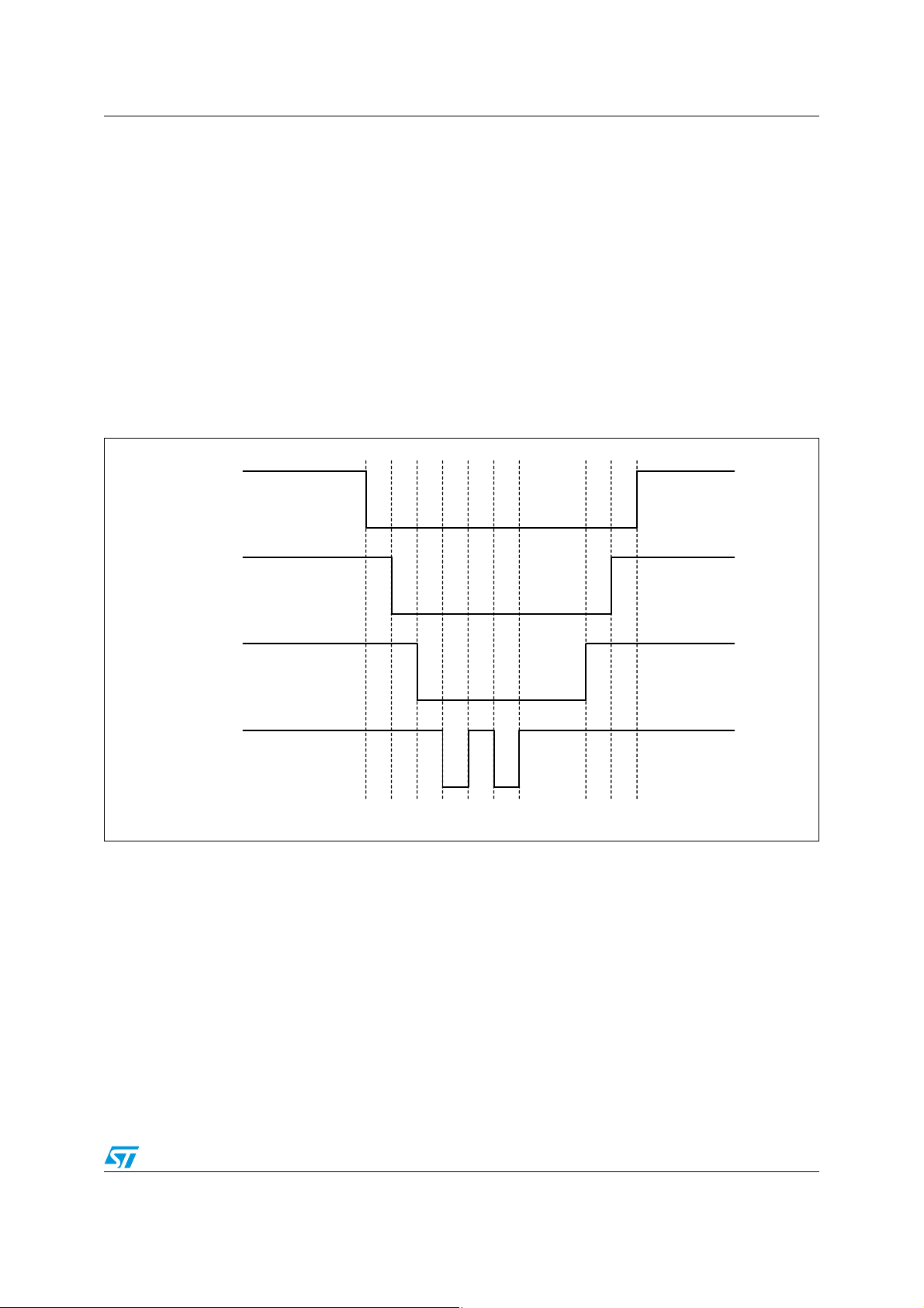
Figure 2. Remote reset request timing
SCS
crosses the 2.5 V value but they can be reset also through
CC
SYN
SCL
SDA
t2t
1
t4t
3
t6t
5
Note: All the time intervals must be longer than 30 ns. t
be longer than 30 ns as well.
4.2 Data registers writing
Each writable bit (configuration and mode signals bits) of STPM01 and STPM10 has its own
6-bit absolute address (see related datasheets for configuration bits map).
t
7
→ t8 is the reset time, this interval must
7
t
t
t
10
8
9
In order to change the state of some pin one must send to STPM01 a byte of data via SPI.
This byte consists of 1-bit data to be written (MSB), followed by 6-bit address of destination
bit, followed by 1-bit don't care data (LSB), which makes a command byte.
For example, to set the STPM01 configuration bit 47 (part of the secondary current channel
calibrator) to 0, the decimal 47 should be first converted to its 6-bit binary value: 101111.
Doc ID 11400 Rev 3 7/23
Page 8

SPI operations AN2159
The command byte will be then composed like this: 1 bit DATA value + 6-bits address +1 bit
(0 or 1). In this case the binary command will be 01011111 (0x5F) or 01011110 (0x5E).
The writing procedure timing is shown in Figure 3.
Figure 3. Timing for writing configuration bits and mode signals
SCS
SYN
SCL
SDA
t
t
2
1
t
→ t2 (> 30 ns): SPI out of idle state
1
t
→ t3 (> 30 ns): SPI enabled for write operation
2
t
: data value is placed in SDA
3
t
: SDA value is stable and shifted into the device
4
t
→ t5 (> 10 µs): writing clock period
3
t
→ t5: 1 bit data value
3
t
→ t6: 6 bits address of the destination latch
5
t
→ t7: 1 bit EXE command
6
t
: end of SPI writing
8
t
: SPI enters idle state
9
t4t
t
3
5
t
t
6
7
t
t
8
9
Commands for changing configuration bits and system signals should be sent during active
signals SCS and SYN as it is shown in Figure 3.
The SYN must be put low in order to disable SDA output driver of the device and make the
SDA as an input pin. A string of commands can be send within one period of active signals
SCS and SYN or command can be followed by reading the data record but, in this case, the
SYN should be deactivated in order to enable SDA output driver and a SYN pulse should be
applied before activation of SCS in order to latch the data.
Given the connection between STPMxx and a microcontroller as shown in the previous
paragraph, it is possible to implement the writing procedure in the firmware through the
following steps:
8/23 Doc ID 11400 Rev 3
Page 9

AN2159 SPI operations
1. disable the SPI peripheral;
2. set MISO, SCLK and SS to be output;
3. set the pin which is connected to SYN to be output high;
4. activate SCS first and then SYN;
5. activate SCL;
6. apply a bit value to SDA and deactivate SCL;
7. repeat the last two steps seven times to complete one byte transfer;
8. repeat the last three steps for any remaining byte transfer;
9. deactivate SYN and the SCS;
10. enable again the SPI module;
Note: For STPM01 only: To temporary set any bit, it is necessary to set the RD system signal
before any other bit. This bit determines the device functioning from OTP shadow latches
and not from OTP memory. The procedure to set this signal is that shown above. For
permanent writing of any bit see next paragraph.
In case of Precharge command (0xFF), emulation above is not necessary, it can be send
before any reading command. In fact, due to the pull up device on the SDA pin the processor
needs to perform the following steps:
1. activate SYN first in order to latch the results;
2. after at least 1 µs activate SCS;
3. write one byte to the transmitter of SPI (this will produce 8 pulses on SCL with SDA=1);
4. deactivate SYN;
5. read the data records as shown in paragraph 4.4 (the sequence of reading will be
altered);
6. deactivate SCS.
Doc ID 11400 Rev 3 9/23
Page 10

SPI operations AN2159
4.3 Data registers permanent writing (STPM01 only)
In order to make a permanent set in OTP memory of some configuration bits, the following
procedure should be conducted:
1. collect all addresses of bits to be permanently set into some list;
2. clear all OTP shadow latches;
3. set the system signal RD;
4. connect a current source of at least +14 V, 1 mA to 3 mA to VOTP pin;
5. wait until VOTP voltage is stable;
6. write one of the bit from the list (since RD signal is set, the bit will be written in the
corresponding OTP shadow latch);
7. set the system signal WE;
8. wait for 300 µs;
9. clear the system signal WE;
10. clear the OTP shadow latch which was set in step 6;
11. until all wanted bits are permanently set, repeat steps 5 to 11;
12. disconnect the current source;
13. wait until VOTP voltage is less than 3 V;
14. clear the system signal RD;
15. read all data records, in the last two of them there is read back of all configuration bits;
16. if verification of CFG bits fails and there is still chance to pass, repeat steps 1 to 16.
For steps of set or clear apply the timing shown in Figure 3 with proper data on SDA.
For step 15 apply the timing shown in Figure 4.
For permanent set of the TSTD bit, which locks the device, the procedure above must be
conducted in such a way that steps 6 to 13 are performed in series during single period of
active SCS because the idle state of SCS would make the signal TSTD immediately
effective.
This would abort the procedure, and it would possibly destroy the device.
In fact the clearing of system signal RD would connect all gates of 3 V NMOS sense
amplifiers of already permanently set bits to the VOTP source.
4.4 Reading data registers
There are two phases of reading, called latching and shifting.
● Latching is used to sample results into transmission latches. This is done with the
active pulse on SYN when SCS is idle. The length of pulse on SYN must be longer than
2 periods of measurement clock, i.e. more than 500 ns.
● Shifting starts when SCS become active. In the beginning of this phase another, but
much shorter pulse (30 ns) on SYN should be applied. An alternative way is to extend
the pulse on SYN into the second phase of reading. Latching and shifting finish at the
dotted line in the timing diagram shown in Figure 4.
10/23 Doc ID 11400 Rev 3
Page 11

AN2159 SPI operations
Figure 4. Timing for reading data registers
SCS
SYN
SCL
SDA
t
1
t1 → t2: Latching phase. Interval value > 2 / f
t
t4t
2
3
t6t
5
t8t
7
last bit of 32ndbyte1stbyte1stbyte
CLK
t2 → t3: Data latched, SPI idle. Interval value > 30 ns
t
→ t4: Enable SPI for read operation. Interval value > 30 ns
3
t
→ t5: Serial clock counter is reset. Interval value > 30 ns
4
t
→ t6: SPI reset and enabled for read operation. Interval value > 30 ns
5
t
: Internal data transferred to SDA
7
t
: SDA data is stable and can be read
8
After the shifting phase, it is possible to read data, applying 32 serial clocks per data record.
Up to 8 data records can be read this way.
Eight 32-bit data registers in STPM01 store relevant measurement information (see related
datasheet for more details). Figure 5 shows the records structure and the information they
hold, the default sequence of reading.
The system that reads the data record from the STPM01 should check the integrity of each
data record. If the check fails, the reading should be repeated, but this time only the shifting
phase should be applied otherwise a new data would be latched into transmission latches
and previous reading would be incorrectly lost.
Doc ID 11400 Rev 3 11/23
Page 12

SPI operations AN2159
Figure 5. STPMxx data registers
20 bit
DAP
4 bit
parity
20 bit 8 bit
1bit
type0 active energy
1bit 1bit
6 bit
Status
DRP
DSP
DFP
DEV
DMV
CFL
CFH
parity
parity
parity
parity
parity
parity
parity
p
p
msb lsb
reactive energy
apparent energy
type 1 energy mode signals
iRMSuRMS
iMOMuMOM
lower part of configurators
upper part of configurators
11 bit 16 bit
upper f(u)0 1
lower f(u)
Most of registers holds several distinctive values of certain bit length, except CFL and CFH
that are holding a bit map of configurators. Most of values are codified as unsigned integer,
except for two values in DMV which are codified as signed binary.
The data records have fixed position of reading. This means that no addressing of records is
necessary.
12/23 Doc ID 11400 Rev 3
Page 13

AN2159 Data processing
5 Data processing
5.1 Reading process
As told before, to start a SPI communication with STPMxx to read new values of registers, it
is necessary to apply a latching phase first. Then a shifting phase starts, as reported in
Figure 4.
After that, 32 pulses of serial clocks needs to be applied to pin SCL in order to read the DAP
register. If additional 32 pulses are applied to pin SCL, the DRP register is read. At this point
there are two possibilities. Either reading is continued by applying 32 clocks per register until
all registers of interest are read or a precharge command is applied first (8 pulses to pin
SCLNLC while SYN=0 and SDA=1) which moves an internal read pointer to register DEV
which effectively skips DSP and DFP registers, and then reading may be continued.
It is up to an application to decide how many records should be read out from the device.
After all registers are read, SCS can be returned to idle state which ends the shifting phase.
Shifting phase can be repeated and it should read the same values. This repetition is used
to improve the reliability of successful reading in a strong EMI environment.
Every register is packed into 4-bytes where the most significant nibble (4 bits) is reserved for
parity code and the rest of 28 bits are used for data. This means that every register is
protected by its own parity bit.
As shown in Figure 6, the first read out byte of data record is Least Significant Byte (LSB) of
data value and the fourth is Most Significant Byte (MSB) of data value, then it is necessary
to re-order the four bytes after reading.
Figure 6. STPMxx data registers
8 bit SPI reading order
1stbyte - LSB
msb lsb
7 07 0 7 07 0
7 07 0 7 07 0
msb lsb
7 07 015 815 823 1623 1600 2424
parity nibble 28 bit data
4thbyte - MSB
parity nibble
32 bits register assembling
Normally, each byte is read out as most significant bit (MSB) first. But this can be changed
by setting the MSBF configuration bit. If this is done, each byte is read out as least
significant bit (LSB) first.
Doc ID 11400 Rev 3 13/23
Page 14

Data processing AN2159
5.1.1 Data register assembling example
Following an example of reading and re-arranging of STPMxx registers.
On the left are reported the eight data records as they are read, represented as
hexadecimal bytes while MSBF was cleared, on the right the corresponding register.
1. 65 7A 7C 82 DAP = 82 7C 7A 65
2. 00 7A 0C E0 DRP = E0 0C 7A 00
3. 00 00 8C 92 DSP = 92 8C 0 00
4. 00 06 6E 22 DFP = 22 6E 06 00
5. BB B3 07 DD DEV = DD 07 B3 BB
6. 3F AF AA CA DMV = CA AA AF 3F
7. 01 00 00 E0 CFL = E0 00 00 01
8. 00 00 00 F0 CFH = F0 00 00 00
5.2 Parity check
Each bit of parity nibble is defined as odd parity of all seven corresponding bits of data
nibbles. In order to check the data record integrity, the application should execute something
similar to the following C code, given as an example:
int BadParity (unsigned char *bp)
{
register unsigned char prty; /* temporary register */
prty = *bp, /* take the 1st byte of data */
prty ^= *(bp+1), /* XOR it with the 2nd byte */
prty ^= *(bp+2), /* and with the 3rd byte */
prty ^= *(bp+3), /* and with the 4th byte */
prty ^= prty<<4, prty &= 0xF0;/* combine and remove the lower nibble */
return (prty != 0xF0); /* returns 1, if bad parity */
}
if (BadParity(dap) || BadParity(drp) || /* DAP and DRP data record */
BadParity(dsp) || BadParity(dfp) || /* DSP and DFP data record */
BadParity(dev) || BadParity(dmv) || /* DEV and DMV data record */
BadParity(cfl) || BadParity(cfh)) /* CFL and CFH data record */
/* code to repeat reading sequence should be entered here */ ;
If the parity nibble check would fail, the reading task should be repeated but, this time,
without request of latching otherwise a new data would be latched and previous reading
would be incorrectly lost.
In a very hash EMI environment, it would be a good practice to read the data records twice
and then compare both reading. This way the probability of detecting bad readings would be
significantly improved. Anyway, a single bad data can be discarded because no meaningful
information is lost as long the reading frequency is about 30 ms.
14/23 Doc ID 11400 Rev 3
Page 15

AN2159 Data processing
5.2.1 Parity check example
Let us consider the example of paragraph 5.1.1 to check the parity of the registers:
1. DAP = 82 7C 7A 65 parity=8,
2. DRP = E0 0C 7A 00 parity=E,
3. DSP = 92 8C 0 00 parity=9,
4. DFP = 22 6E 06 00 parity=2,
5. DEV = DD 07 B3 BB parity=D,
6. DMV = CA AA AF 3F parity=C,
7. CFL = E0 00 00 01 parity=E,
8. CFH = F0 00 00 00 parity=F,
Most likely, the STPM01 is not responding (is not selected), if any data record is read as:
X. FF FF FF FF parity=F, (parity check will fail)
Let's check the parity code of the first data record. The following steps should be performed
using temporary variable named HL:
1. load the 1st byte into HL HL = 65 = 0110 0101
2. exor HL with the 2nd byte: HL = 65^7A = 0110 0101 ^ 0111 1010
3. exor HL with the 3rd byte: HL = 1F^7C = 0001 1111 ^ 0111 1100
4. exor HL with the 4th byte: HL = 63^82 = 0110 0011 ^ 1000 0010
5. exor HL with HL<<4: HL = E1^10 = 1110 0001 ^ 0001 0000
6. and HL with 0xF0: HL = F1&F0 = 1111 0001 & 1111 0000
7. compare HL with 0xF0: HL = F0 = 1111 0000
Let check also the parity code of the fourth data record:
1. load the 1st byte into HL: HL = 00 = 0000 0000
2. exor HL with the 2nd byte: HL = 00^06 = 0000 0000 ^ 0000 0110
3. exor HL with the 3rd byte: HL = 06^6E = 0000 0110 ^ 0110 1110
4. exor HL with the 4th byte: HL = 68^22 = 0110 1000 ^ 0010 0010
5. exor HL with HL<<4: HL = 4A^A0 = 0100 1010 ^ 1010 0000
6. and HL with 0xF0: HL = EA&F0 = 1110 1010 & 1111 0000
7. compare HL with 0xF0: HL = E0 = 1110 0000
This time the parity is not correct.
5.3 Unpacking data
After reading (and following re-ordering of bytes read), each register should be unpacked in
order to obtain all individual values.
For this purpose it is necessary to mask the 28 bits according to the registers map shown in
Figure 5. For example, DAP register is unpacked into 8-bit value of status (least significant
byte) and 20-bit value of active energy counter (remaining upper 3 bytes with parity code
masked out).
Doc ID 11400 Rev 3 15/23
Page 16

Converting readings into measured values AN2159
6 Converting readings into measured values
6.1 Energies
The first four registers contain 20 bit value of internal energy up/down counters.
The value of least significant bit of every energy counter is related to power meter constant
P, which is the number of pulses per kWh that the meter, through calibration, is configured to
provide to LED pin.
This means that this value changes with the application and relative calibration.
Given P, the value of the LSB of the source energy registers is indicated below:
K
= 1000 / (2
AW
K
AWFund
K
RW
K
SW
= 4 * KAW [Wh] (active fundamental energy);
= 2 * KAW [VARh] (reactive energy);
= KAW [VAh] (apparent energy).
For example, if P = 64000 imp/kWh:
K
= 7.63 * 10-6 Wh
AW
K
AWFund
K
RW
K
SW
= 3.05 * 10-5 Wh
= 1.52 * 10-5 VARh
= 7.63 * 10-6 VAh
This also means that the STPMxx energy counters hold a very small energy value (in the
example above, the active energy register stores about 8 Wh), and further energy
integration has to be performed inside the application.
11
* P) [Wh] (active energy);
To accomplish this task, the below procedure should be followed.
Because all energy counters rollover in approximately 1 s when they are integrating maximal
power, the reading must be done frequently enough. Our suggestion is to read the registers
at least 32 times per second.
For each energy type a variable e should be allocated, having the following structure (below,
the variable definition for an ST7 microcontroller):
typedef struct energ {
unsigned long old; /* previous energy value - 32 bits */
unsigned int quot; /* quant/16 - 16 bits */
signed int quant; /* new - old, measure of power - 16 bits */
signed long frac; /* fractional part of energy integrator - 32 bits */
signed long integ; /* integer part of energy integrator - 32 bits */
} ENERG;
The application should keep previous value of each energy counter in order to evaluate the
difference of readings, from which also a direction of energy flow can be obtained. This
value should be stored in e
register reading should be stored in e
→
old before a reading. After the reading, the new energy
→
new.
To calculate consummated energy the software should implement a 32-bit integrator. The
suggested integrator is two stages, with e
variables. Into e
→
frac is added the value e → quant, obtained as difference between e →
→
frac and e → integ 32-bit signed integer
16/23 Doc ID 11400 Rev 3
Page 17

AN2159 Converting readings into measured values
old and e → new energy values; then e → old value should be rewritten with e → new
value in order to enable a correct e
→
quant computation next time.
When e
(corresponding to a certain threshold value according to K
1 bit and the e
This way e
→
frac would collect a certain amount of energy, let say 10 Wh for active energy
), e → integ should change for
→
frac should change by the threshold value.
→
frac stores 0.01 kWh, after which e → integ is increased by one, and e →
AW
integ variable will hold accumulated energy of which the least significant bit will represent
10 Wh.
Considering an active energy meter where P = 64000 imp/kWh, for a step of 0.01 kWh = 10
Wh, since each bit of e'quant represents K
counter, because e
the threshold value will be 10 / K
→
quant is calculated as a difference of two energy counter values),
= 10 * 2^17 = 0 x 140000.
AW
Wh (is the same resolution of internal energy
AW
In a microcontroller based application, a high priority timer interrupt should be set to perform
measuring tasks every 1/512 s. Within this interrupt service 16 different subtasks could be
established in order to broke the whole meter task into 16 shorter consecutive subtasks
(reading of device's register, checking the data read and if OK, computing the value of e
→
quant, ...). In this way the main program and other interrupt services are not blocked for
more than few 100 µs every 2 ms, and the meter task will be completed in 16 steps - that is
in 1/32 s.
The interrupt service should do the following:
● update e
● generate output pulses (if needed) from e
● call the next subtask
● perform other tasks (if needed)
→
frac and e → integ of energy variable using e → quot = e → quant / 16
→
frac
In this way the addition of e
→
quant is split in 16 times. This generates a microcontroller
output pulse that has a 16 times better accuracy of position in time. In fact the period of
reading would be 1/32 s = 31.25 ms. If the whole value of e
final energy register e
→
frac, only 31.25 ms resolution of output pulse position would be
→
quant would be added to the
possible, which would be seen as a jitter just by eye looking to the LED. Using suggested
method the resolution of output pulse position would be 1.95 ms, which is short jitter enough
that nobody would see it.
Below an example of subtasks organization is given:
subtask_0: latch the values in the STPMxx
subtask_1: read the STPMxx
subtask_2: repeat the reading of STPMxx (without latching again) and stop SPI
communication
subtask_3: verify the parity codes of registers and equality of both readings, result is flag OK
subtask_4: if OK unpack values of registers read from STPMxx
subtask_5: if OK process STPMxx status
subtask_6: if OK compute e
subtask_7: if OK compute e
subtask_8: if OK compute e
subtask_9: if OK calculate V
→
quant and update e → old of active energy
→
quant and update e → old of reactive energy
→
quant and update e → old of apparent energy
rms
and I
rms
,
Doc ID 11400 Rev 3 17/23
Page 18

Converting readings into measured values AN2159
subtask_A: convert e → integ of active energy into format suitable for LCD
subtask_B: convert e
subtask_C: convert e
subtask_D: convert V
subtask_E: convert I
subtask_F:
if not OK e
→
quant = 0
else {
e
update e
e
→
quot = e → quant % 16, (is the remainder of e → quant / 16)
→
frac of active energy using e → quot,
→
quot = e → quant / 16
}
6.2 Other values
The ratio between the register value and the actual voltage, current or frequency value is a
function of the voltage and current sensors sensitivity and of the device internal parameters,
like analog amplification, reference voltage, measurement frequency, calibrator, attenuation
of each stage of decimation filter and power meter constant.
→
integ of reactive energy into format suitable for LCD
→
integ of apparent energy into format suitable for LCD
into format suitable for LCD
rms
into format suitable for LCD
rms
Formulas to convert the readings into meaningful values are reported below.
In any case, since the internal parameters values, here given as constants, are subject to
process drift, and the sensors sensitivity are subject to tolerance, even if these fluctuations
are compensated by the calibrators, the best way to obtain the proper parameters is to
measure known signals and calculate the ratio between register value and actual value. The
device linearity will ensure that the ratio will remain constant.
Figure 7, Figure 8 and Figure 9 below shown the signal processing chains for current and
voltage.
Figure 7. Voltage signal path
18/23 Doc ID 11400 Rev 3
Page 19

AN2159 Converting readings into measured values
Figure 8. Current conditioning
Figure 9. Current signal path
Each block of the path contributes to the signal processing with the parameters shown
below.
Ta bl e 2 shows the variable parameters that must be consider as inputs for the following
calculation while Ta bl e 3 shows device internal constant parameters.
Table 2. Input parameters
Parameter Meaning
R1, R2 Voltage Divider Resistors Value [Ohm]
Ks Current Sensor Sensitivity Value [V/A]
x_i_rms RMS Current Register Value expressed as decimal
x_u_rms RMS Voltage Register Value expressed as decimal
x_i_mom Momentary Current Register Value expressed as decimal
x_u_mom Momentary Voltage Register Value expressed as decimal
x_f Frequency Register Value expressed as decimal
Ai Current Channel Gain
The value of the current channel gain Ai depends on the selected current sensor. Please
refer to the datasheet for the proper value to select.
Doc ID 11400 Rev 3 19/23
Page 20

Converting readings into measured values AN2159
Table 3. STPMxx internal parameters value
Parameter Value Meaning
Ku 0,875 Voltage Calibrator Ideal Value
Ki 0,875 Current Calibrator Ideal Value
Au 4 Voltage Channel Gain
len_i 2^16 RMS Current Register Length
len_u 2^11 RMS Voltage Register Length
len_i_mom 2^15 Momentary Current Register Length
len_u_mom 2^10 Momentary Voltage Register Length
len_f 2^14 Frequency Register Length
Kint_comp 1,004 Gain of decimation filter
π 3.14159
Dint 2^16
Dint_p 2^15
Fm
Kut
Vref 1.23 Internal voltage reference
2^23 if oscillator frequency is 4.194 or 8.388 MHz
8 * 10^6 if oscillator frequency is 4.000 or 8.000 MHz
2 for CT/Shunt
1 for Rogowski coil
Line frequency is calculated as follows:
frequency = 2 * Fm * x_f /( π * len_f * Dint)
kf = frequency / 50
The differentiator and integrator gains are calculated from the frequency result as follows:
Kdif = (2* π * frequency * Dint_p) / (2 * Fm)
Kint = Fm * 2 / (2 * π * frequency * Dint)
Typical values are:
Kdif
Kint
0,6135 Gain of differentiator @ line frequency = 50 Hz
0.7359 Gain of differentiator @ line frequency = 60 Hz
0,815 Gain of integrator @ line frequency = 50 Hz
0.679 Gain of integrator @ line frequency = 60 Hz
20/23 Doc ID 11400 Rev 3
Page 21

AN2159 Converting readings into measured values
For momentary values it is necessary first of all to evaluate their sign:
if (x_i_mom & 0x08000) // positive current
x_i_mom = x_i_mom & 0x07FFF;
else // negative current
{
x_i_mom = 0x08000 - x_i_mom;
x_i_mom = x_i_mom * (-1);
}
if (x_u_mom & 0x0400 // positive voltage
x_u_mom = (x_u_mom) & 0x3FF;
else // negative voltage
{
x_u_mom = 0x0400 - (x_u_mom);
x_u_mom = x_u_mom * (-1);
}
The current and voltage conversion formulas in case of Rogowski Coil current sensor are:
u_rms = (1+R1/R2) * x_u_rms *Vref /(Au * Ku * Kint_comp * len_u * Kut)
i_rms = x_i_rms * Vref /(Ks * Kf * Ai * Ki * Kint * Kint_comp * len_i)
u_mom = (1+R1/R2) * x_u_mom * Vref /(Au * Ku * Kint_comp * len_u_mom * Kut)
i_mom = x_i_mom * Vref /(Ks * Kf * Ai * Ki * Kint * Kint_comp * len_i_mom)
In case of current trasformer or Shunt sensor the formulas become:
u_rms = (1+R1/R2) * x_u_rms *Vref /(Au * Ku * Kint_comp * Kint * Kdif * len_u * Kut)
i_rms = x_i_rms * Vref/(Ks * Ai * Ki * Kint * Kint_comp * Kdif * len_i)
u_mom = (1+R1/R2) * x_u_mom * Vref /(Au * Ku * Kint_comp * Kint * Kdif * len_u_mom *
Kut)
i_mom = x_i_mom * Vref /(Ks * Ai * Ki * Kint * Kint_comp * Kdif * len_i_mom)
Doc ID 11400 Rev 3 21/23
Page 22

Revision history AN2159
7 Revision history
Table 4. Document revision history
Date Version Description
18-Jun-2005 1 First release
19-Apr-2006 2 Document reformatted no content change
26-Jul-2010 3 Added: Figure 1 on page 1, Section 1.1 and Section 1.2 on page 3
22/23 Doc ID 11400 Rev 3
Page 23

AN2159
Please Read Carefully:
Information in this document is provided solely in connection with ST products. STMicroelectronics NV and its subsidiaries (“ST”) reserve the
right to make changes, corrections, modifications or improvements, to this document, and the products and services described herein at any
time, without notice.
All ST products are sold pursuant to ST’s terms and conditions of sale.
Purchasers are solely responsible for the choice, selection and use of the ST products and services described herein, and ST assumes no
liability whatsoever relating to the choice, selection or use of the ST products and services described herein.
No license, express or implied, by estoppel or otherwise, to any intellectual property rights is granted under this document. If any part of this
document refers to any third party products or services it shall not be deemed a license grant by ST for the use of such third party products
or services, or any intellectual property contained therein or considered as a warranty covering the use in any manner whatsoever of such
third party products or services or any intellectual property contained therein.
UNLESS OTHERWISE SET FORTH IN ST’S TERMS AND CONDITIONS OF SALE ST DISCLAIMS ANY EXPRESS OR IMPLIED
WARRANTY WITH RESPECT TO THE USE AND/OR SALE OF ST PRODUCTS INCLUDING WITHOUT LIMITATION IMPLIED
WARRANTIES OF MERCHANTABILITY, FITNESS FOR A PARTICULAR PURPOSE (AND THEIR EQUIVALENTS UNDER THE LAWS
OF ANY JURISDICTION), OR INFRINGEMENT OF ANY PATENT, COPYRIGHT OR OTHER INTELLECTUAL PROPERTY RIGHT.
UNLESS EXPRESSLY APPROVED IN WRITING BY AN AUTHORIZED ST REPRESENTATIVE, ST PRODUCTS ARE NOT
RECOMMENDED, AUTHORIZED OR WARRANTED FOR USE IN MILITARY, AIR CRAFT, SPACE, LIFE SAVING, OR LIFE SUSTAINING
APPLICATIONS, NOR IN PRODUCTS OR SYSTEMS WHERE FAILURE OR MALFUNCTION MAY RESULT IN PERSONAL INJURY,
DEATH, OR SEVERE PROPERTY OR ENVIRONMENTAL DAMAGE. ST PRODUCTS WHICH ARE NOT SPECIFIED AS "AUTOMOTIVE
GRADE" MAY ONLY BE USED IN AUTOMOTIVE APPLICATIONS AT USER’S OWN RISK.
Resale of ST products with provisions different from the statements and/or technical features set forth in this document shall immediately void
any warranty granted by ST for the ST product or service described herein and shall not create or extend in any manner whatsoever, any
liability of ST.
ST and the ST logo are trademarks or registered trademarks of ST in various countries.
Information in this document supersedes and replaces all information previously supplied.
The ST logo is a registered trademark of STMicroelectronics. All other names are the property of their respective owners.
© 2010 STMicroelectronics - All rights reserved
STMicroelectronics group of companies
Australia - Belgium - Brazil - Canada - China - Czech Republic - Finland - France - Germany - Hong Kong - India - Israel - Italy - Japan -
Malaysia - Malta - Morocco - Philippines - Singapore - Spain - Sweden - Switzerland - United Kingdom - United States of America
www.st.com
Doc ID 11400 Rev 3 23/23
 Loading...