

AN2148
APPLICATION NOTE
STOTG04 IN AUDIO CARKIT ENVIRONMENT
1 - INTRODUCTION
This application note describes the application of the STOTG04 full-speed USB-OTG transceiver in an
audio carkit environmen t. The paper also illustrates the carkit use and operation, connection b etween
cellular phone and the carkit, physical co nnection and external circuitry of the STOTG04 required for a
correct operation. Proper setup of the internal registe rs of the STOTG04 ne eded for aud io mode is a lso
described. The information in this application note is intended for system design engineers who plan to
use the STOTG0 4 transceiver as a USB -OTG physical layer device i n equipment using the un iversal
serial bus even for audio signals.
Specification [3] defines a standard method for routing audio and UART signals to an analog carkit and
other accessories (chargers and RS232 devices) th rough a phone’s Mini-AB USB receptacle. A carkit
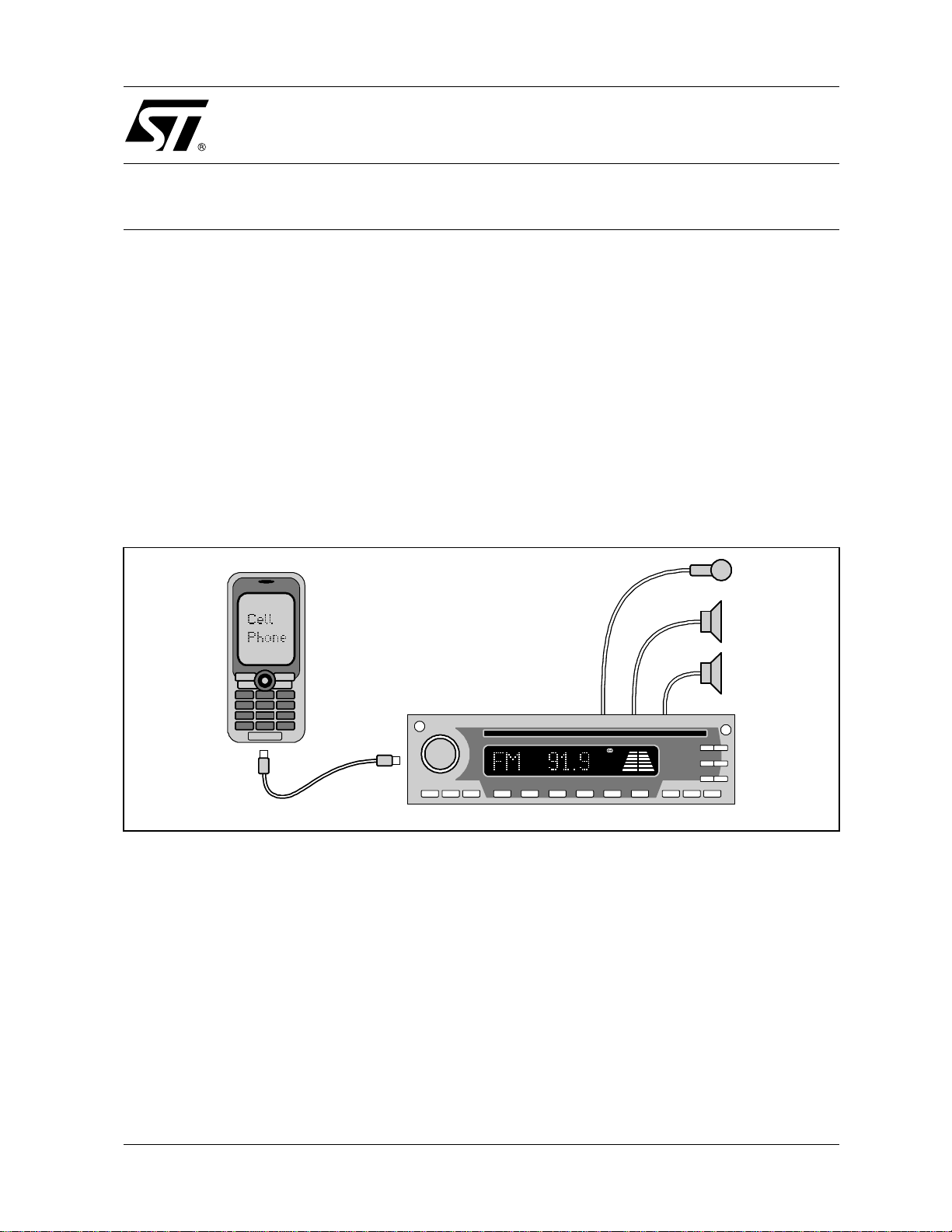
consists of a m icrophone, speaker, and Mini-B plug to connect a p hone. It may also c ontain a button,
LED, and a cradle for the phone. The carkit may be integrated into a car stereo as shown in Figure 1. The
connection between a phone and a carkit can be provided using either a standard Mini-USB cable with
four wires plus shield or a captive cable with five wires plus shield.
Figure 1 : Car S ter eo Carkit I m plement ation
Cellular Phone
Mini-B Plug
Mini-A Plug
The carkit interface is intended to enable the following features between a phone and a car stereo:
– pho ne charg ing
– hands free speakerphone
– push-to-talk
– ster eo playback
– others (like telematics, navigation system, etc.)
As most phones currently support USB signaling, it is planned that car stereos will support USB too. It will
allow the transfer of following data using the universal serial bus:
– aud io files
– video files
– images
– data
Car HiFi with Integrated CarkitCar HiFi with Integrated Carkit
Car Stereo with Integrated Carkit
Rev. 1
1/8May 2005
AN2148 - APPLICAT ION NOTE
2 - CARKIT INTERFACE ARCHITECTURE
The phone‘s Mini-AB USB receptacle consists of four signal lines (VBUS, D+, D-, and ID), ground, and a
shield. The carkit interface allows the use of these wires in three different signaling modes:
– UART mode
– mono m ode
– ster eo mode
Alternate functions of the USB signal lines are described in Table 1 for each particular carkit signaling
mode.
Table 1 : Alternate Functions of a USB Signal Lines
Line UART Mode Mono Mode Stereo Mode
VBUS VBUS VBUS VBUS
D+ RXD MIC SPKR_R
D- TXD SPKR SPKR_L
ID CTL* CTL* CTL*
GND GND GND GND
SHLD SHLD CMR CMR
Note (*) The ID line is not required for 4-wire carkit interface
In all three modes, the VBUS, GND, SHL D, and ID lines perform the same function. T he VBUS line
carries a 5V supply voltage from the carkit to the phone. The GND lin e is a common ground carrying
return current from the phone t o the carkit. The SHLD acts as an a nalog reference between the pho ne
and the carkit. The ID line is used to signal interrupt and control i nfo rmation for the five-wire protocol. If a
phone is connected to a carkit using standard Mini-USB cable, it is not possible to use the ID line for
signaling. In this case, it is necessary to use the four-wire comm unication protocol between the phone
and carkit. When the cark it contains captive cable with an ID wire, then it is p ossible to use either the
four-wire or five wire protocol. Both these protocols are defined in the specification [3].
In UART mode, the D- line carries the TXD signal from the phone to the carkit, and the D+ line carries the
RXD signal from the carkit to the phone.
In mono mode, the D- line carries the m ono speaker signal from t he phone to the carkit and th e D+ line
carries the microphone signal from the carkit to the phone.
In stereo mode, the D- line carries the left speaker signal from the phone to the carkit and the D+ li ne
carries the right speaker signal from the phone to the carkit.
2/8
AN2148 - APPLICAT ION NOTE
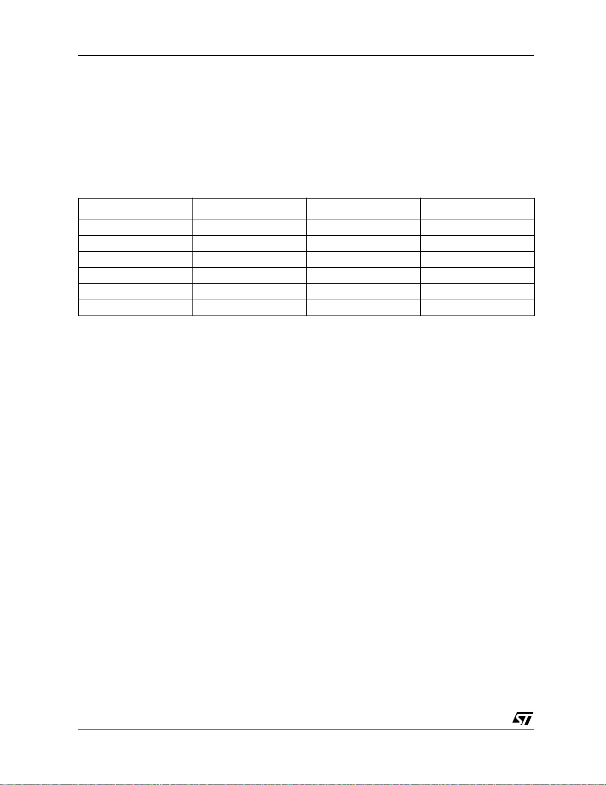
The carkit connection architecture is shown in the two figures below. Figure 2 shows the interface
between a phone and a carkit using standard Mini-USB cable.
Figure 2 : Carkit Four-Wire Interface
Power Management
5V_IN
USB-OTG Controller
SDA
SCL
RCV
OE_N
VP
VM
Phone Pro cessor
RXD
TXD
SPKR_MIC
SPKR_L
USB-OTG Transceiver
V
SDA
SCL
RCV
OE_TP_INT/
DAT_VP
SE0_VM
BUS
D+
DID
Mini-AB
Receptable
V
BUS
D+
DID
GND
SHLD
V
BUS
D+
DID
GND
SHLD
Standard Mini-USB Cab le
V
BUS
D+
DID
GND
SHLD
Mini-A
Receptable
V
BUS
D+
DID
GND
SHLD
Voltage Regulator
5V_OUT
Carkit Amplifier
SPKR_MIC
SPKR_L
CMR
RXD_SDA
TXD_SCL
Carkit Control
Figure 3 shows the interface between a phone and a carkit using captive cable with five wires.
Figure 3 : Carkit Five-Wire Interface
Power Mana ge m ent
5V_IN
USB-OTG Controller
SDA
SCL
RCV
OE_N
VP
VM
USB-OTG Transceiver Mini-AB
SDA
SCL
RCV
OE_TP_INT/
DAT_VP
SE0_VM
V
BUS
D+
DID
Receptable
V
BUS
D+
DID
GND
SHLD
V
GND
SHLD
BUS
D+
DID
Voltage Regulator
5V_OUT
Carkit Amplifier
SPKR_MIC
SPKR_L
CMR
Phone Processor
RXD
TXD
SPKR_MIC
SPKR_L
RXD_SDA
TXD_SCL
Carkit Control
3/8
AN2148 - APPLICAT ION NOTE
3 - STOTG04 APPLICATION
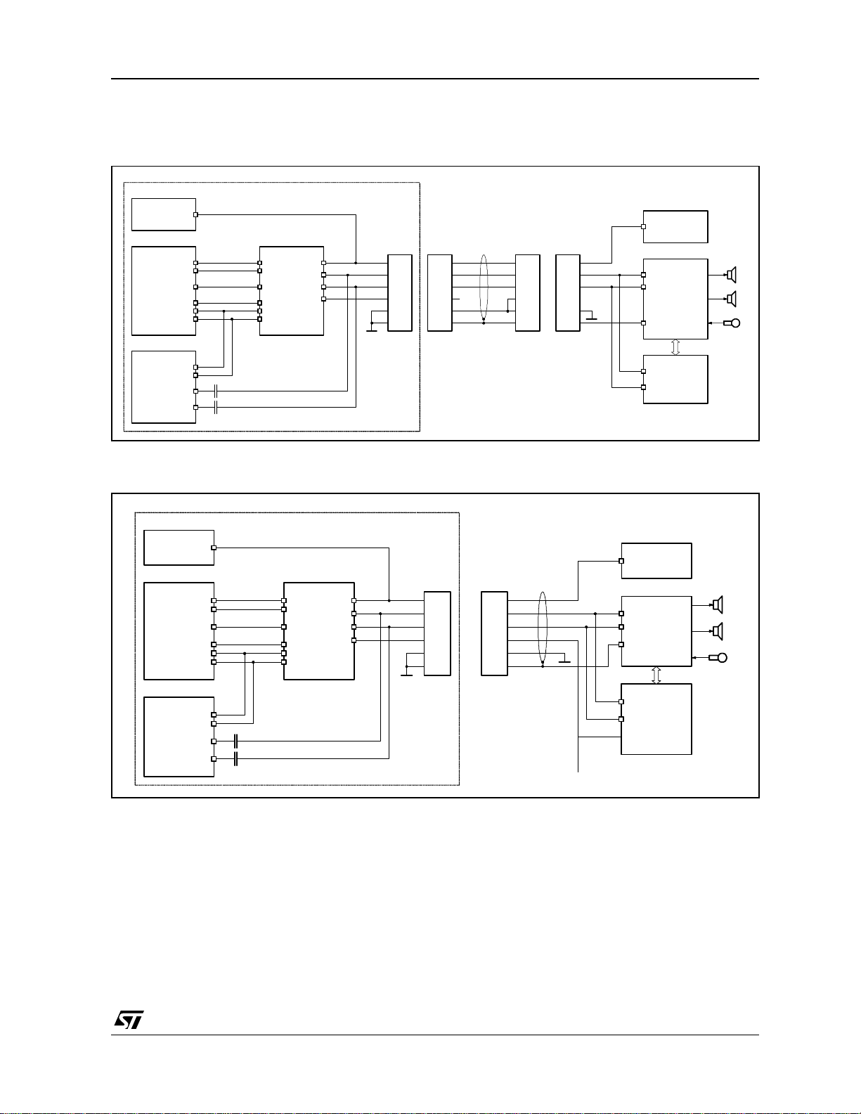
The STOTG04 transceiver supports carkit signaling on both D+ and ID lines. Therefore, it is able to
operate with both fo ur-wire and five-wire protocol. It is up t o the carkit a ccessory whic h protocol w ill be
used. Figure 4 shows connection of the STOTG04 full-speed USB-OTG transceiver in an application
requiring even audio mode operation.
Figure 4 : Carkit Five-Wire Interface
1.6–3.6 V
USB-OTG Controller
VCC
Phone Processor
VCC
INT/
RESET/
SDA
SCL
VM
VP
RCV
OE_TP_INT/
SE0_VM
DAT_VP
TXD
RXD
SPKR_MIC
SPKR_L
STOTG04E
VIF
SPEED
SUSPEND
INT/
RESET/
SDA
SCL
ADR_PSW
VM
VP
RCV
OE_TP_INT/
SE0_VM
DAT_VP
GND
VBAT
CAP1
CAP2
D+
VBUS
VTRM
CGND
2.7–5.0 V
220nF
Mini-AB
ID
D-
20Ω±5%
4.7
µ
F1µF
ID
D+
D-
VBUS
GND
The transceiver in Figure 4 can operate in all four operating modes: USB, I
2
C, UART, and audio. For
operation in audio mo de it is necessary to release internal drivers to forc e the D+ and D- li nes into high
impedance state. The UA RT mode is also needed for carkit. To use the transceiver in the UART mode it
is necessary to properly set the direction of UART drivers. The correct setup of control registers of the
transceiver is described in Table 2 for both audio and UART modes.
Table 2 : Alternate Functions of a USB Signal Lines
Register UART Mode Audio Mode
Control 1 x 1 x x 0 x x x
(transp_en = 0, uart_en = 1)
Control 2 0 0 0 0 0 0 0 0
(release all PU/PD resistors)
Control 3 x x x 1 0 x x x
(bdir[0] = 0, bdir[1] = 1)
x 0 x x 0 x x x
(transp_en = 0, uart_en = 0)
0 0 0 0 0 0 0 0
(release all PU/PD resistors)
x x 1 x x x x x
(audio_en = 1)
In the UART mode after a proper setup it is possibl e to transm it data from the SE0_V M pin to the D- li ne
and to receive data from the D+ line on the DAT_VP pin.
4/8

AN2148 - APPLICAT ION NOTE
In audio mode it is necessary to tie the O E_TP_INT/ pin to a high level to deactivate the USB d river.
When all the pull-u p and pull-down res istors are disconnec ted, the D+ and D- USB lines will b e in high
impedance state and it is possible to send audio signals over the lines. To be able to detect carkit
interrupts, it is necessary to set the audio_en bit of the Control Register 3. Then, depending on the
protocol used (either four-w ire or five-wire) it is necessary to set the proper b its of the Interrupt Mask
False and Interrupt Mask True registers. If a four-wire protocol is used th en D+ carkit interrupt should be
utilized and therefore the cr_int bit of interrupt mask registers should be set. If a five-wire protocol is used
then ID line carkit interrupt can be utilized and therefore the id_gnd bit of interrupt registers should be set.
5/8

AN2148 - APPLICAT ION NOTE
4 - REFERENCES
The following publications contain detailed information regarding the topic of this application note:
1 STOTG04 USB-OTG Full-Speed Transceiver Datasheet
2 CEA-2011, OTG Transceiver Specification
3 CEA-936-A, Mini-USB Analog Carkit Interface
4 OTG Carkit Transceiver, revision 0.63
6/8

5 - REVISON HISTORY
Table 3 : Revision History
Date Revision Description of Changes
12-May-2005 1 First Release.
AN2148 - APPLICAT ION NOTE
7/8

AN2148 - APPLICAT ION NOTE
Information furnished is believed to be accurate and reliable. However, STMicroelectronics assumes no responsibility for the consequences
of use of su ch i nf orm ati on n or f or any i nfri ng eme n t of pa te nt s or ot her r igh ts of thi r d pa rt ies whi c h m ay re su lt fr om its us e. No lic ense is granted
by impl i cation or o therwise under any p atent or patent right s of STMicr oelectronics. Specif i cations mentioned i n this publi cation are subject
to change without notice. This publication supersedes and replaces all information previously supplied. STMicroelectronics products are not
authorized for use as critical components in life support devices or systems without express written approval of STMicroelectronics.
The ST logo is a registered trademark of STMicroelectronics.
All other na mes are the p roperty of the i r respectiv e owners
© 2005 STMic roelectronics - All rights reserved
STMicroelectronic s group of comp anies
Australi a - B el gium - Braz i l - Canada - Chin a - Czech Repu bl i c - Finland - F rance - Germany - Hong Kon g - India - Israel - Italy - Japan -
Malaysi a - Malta - Morocco - Sing apore - Spain - Sweden - Swi tz erland - Un ited Kingdo m - Uni t ed States of America
www.st.com
8/8
 Loading...