

Page 1

AN2077
APPLICATION NOTE
EEPROM Emulation with STR71x
INTRODUCTION
External EEPROMs are often used in applications to store data that may be later updated or
adjusted. On the other hand, the microcontrollers used in these systems are based more and
more on embedded Flash.
The trend to continuously reduce the number of components is forcing designers to look to use
Flash memory to emulate EEPROM.
This application note explains the differences between external EEPROMs and embeddedFlash and gives advice on how to substitute external EEPROM to emulated-EEPROM using
the on-chip Flash of STR71xF devices.
Although the concept is easy to explain and implement “as is”, there are some embedded aspects that have to be taken into account.
Substituting external EEPROM with emulated EEPROM from the embedded-Flash of the microcontroller is a complex development. This application note assumes that readers are already familiar with the techniques used to secure the content of evolutive information in external EEPROM of embedded applications.
This application note is organized in 4 parts:
– Description of the differences between external EEPROMs and embedded-Flash,
– General description of EEPROM emulation concept,
– Introduction to embedded application aspects,
– Software example.
Although this application note is mainly refers to STR710FZ1, STR710FZ2, STR711FR1,
STR711FR2, STR712FR2 and STR712FR2,
crocontroller.
most of its content is not dependent on the mi-
Rev. 2.0
AN2077/0705 1/19
1
Page 2

Table of Contents
INTRODUCTION . . . . . . . . . . . . . . . . . . . . . . . . . . . . . . . . . . . . . . . . . . . . . . . . . . . . . . . 1
1 EMBEDDED FLASH AND EEPROM . . . . . . . . . . . . . . . . . . . . . . . . . . . . . . . . . . . . . . 3
1.1 DIFFERENCE IN WRITE ACCESS TIME . . . . . . . . . . . . . . . . . . . . . . . . . . . . . . 3
1.2 DIFFERENCE IN WRITING METHOD . . . . . . . . . . . . . . . . . . . . . . . . . . . . . . . . . 3
1.3 DIFFERENCE IN ERASE TIME . . . . . . . . . . . . . . . . . . . . . . . . . . . . . . . . . . . . . . 4
1.4 ADDITIONAL INFORMATION ON FLASH . . . . . . . . . . . . . . . . . . . . . . . . . . . . . 4
2 EEPROM EMULATION CONCEPT . . . . . . . . . . . . . . . . . . . . . . . . . . . . . . . . . . . . . . . 5
2.1 PRINCIPLE . . . . . . . . . . . . . . . . . . . . . . . . . . . . . . . . . . . . . . . . . . . . . . . . . . . . . . 5
2.2 PROGRAM/ERASE CYCLE . . . . . . . . . . . . . . . . . . . . . . . . . . . . . . . . . . . . . . . . . 6
2.3 READ-WHILE-WRITE . . . . . . . . . . . . . . . . . . . . . . . . . . . . . . . . . . . . . . . . . . . . . 6
2.4 FLASH ORGANIZATION . . . . . . . . . . . . . . . . . . . . . . . . . . . . . . . . . . . . . . . . . . . 6
2.5 DATA-SET STATUS BITS . . . . . . . . . . . . . . . . . . . . . . . . . . . . . . . . . . . . . . . . . . 6
2.6 ACTIVE FLASH BANK SELECTION . . . . . . . . . . . . . . . . . . . . . . . . . . . . . . . . . . 7
3 EMBEDDED APPLICATION ASPECTS . . . . . . . . . . . . . . . . . . . . . . . . . . . . . . . . . . . 8
3.1 READING THE FLASH WHILE ERASING OR PROGRAMMING . . . . . . . . . . . . 8
3.1.1 Suspend and resume commands . . . . . . . . . . . . . . . . . . . . . . . . . . . . . . . . . . . . . . . 8
3.1.2 Minimum software to be copied into the on-chip RAM . . . . . . . . . . . . . . . . . . . . . . . . 9
3.2 DATA PROGRAMMING / ERASING WITH STR71XF . . . . . . . . . . . . . . . . . . . . 9
3.2.1 Flash field reprogramming . . . . . . . . . . . . . . . . . . . . . . . . . . . . . . . . . . . . . . . . . . . . . 9
3.3 FIELD REPROGRAMMING WITH STR71XF . . . . . . . . . . . . . . . . . . . . . . . . . . 10
3.3.1 Field events and Flash reliability . . . . . . . . . . . . . . . . . . . . . . . . . . . . . . . . . . . . . . . 10
3.3.2 List of Events and Suggested Handling Methods . . . . . . . . . . . . . . . . . . . . . . . . . . 10
4 SOFTWARE EXAMPLE . . . . . . . . . . . . . . . . . . . . . . . . . . . . . . . . . . . . . . . . . . . . . . . 12
4.1 SOFTWARE EXAMPLE CONCEPT . . . . . . . . . . . . . . . . . . . . . . . . . . . . . . . . . 12
4.2 SOFTWARE OUTPUT FUNCTIONS . . . . . . . . . . . . . . . . . . . . . . . . . . . . . . . . . 13
4.2.1 EEPROM_Init . . . . . . . . . . . . . . . . . . . . . . . . . . . . . . . . . . . . . . . . . . . . . . . . . . . . . . 14
4.2.2 EEPROM_DataRead . . . . . . . . . . . . . . . . . . . . . . . . . . . . . . . . . . . . . . . . . . . . . . . . 14
4.2.3 EEPROM_DataWrite . . . . . . . . . . . . . . . . . . . . . . . . . . . . . . . . . . . . . . . . . . . . . . . . 14
4.3 EEPROM OUTPUT FUNCTIONS USE EXAMPLE . . . . . . . . . . . . . . . . . . . . . . 15
5 SUMMARY . . . . . . . . . . . . . . . . . . . . . . . . . . . . . . . . . . . . . . . . . . . . . . . . . . . . . . . . . 17
6 REVISION HISTORY . . . . . . . . . . . . . . . . . . . . . . . . . . . . . . . . . . . . . . . . . . . . . . . . . 18
2/19
1
19
Page 3

EEPROM Emulation with STR71x
1 EMBEDDED FLASH AND EEPROM
Before describing the proposed concept for EEPROM emulation, it is important to bear in mind
the main differences between the embedded-Flash memory of a microcontroller and serial ex
ternal EEPROMs. These differences apply to any microcontroller (i.e. not specific to STR71xF
variants). They are summarized in the table below.
Table 1. Differences between Embedded Flash and EEPROM
-
Feature EEPROM
several ms
Write time
Erase time N/A
Write method
Write access
random byte: 5 to 10ms
page: equivalent to hundred µs / word (5 to
10ms per page)
once started, is not CPU-dependent;
needs only proper supply.
serial: hundred µs
random word: 92µs
page: 22.5µs /byte
Emulated EEPROM from Embedded-
Flash
several µs
(ex: 16µs per word)
seconds
(ex: 1.5s)
once started, is CPU-dependent: a CPU
reset will stop the write process even if
supply stays within specification.
parallel: hundred ns
a small number of CPU cycles per word.
1.1 DIFFERENCE IN WRITE ACCESS TIME
As Flash has a shorter write access time, critical parameters can be stored faster in the emulated EEPROM than in a serial external EEPROM, thereby improving the robustness of the
system if the same safety concept is kept.
1.2 DIFFERENCE IN WRITING METHOD
One of the important differences between external EEPROM and emulated EEPROM for embedded applications is the writing method.
– Stand-alone external EEPROM: once started by the CPU, the writing of a word cannot be
interrupted by a CPU reset. Only supply failure will interrupt the writing process; so properly
sizing the decoupling capacitors can secure the complete writing process inside a standalone EEPROM.
– Emulated EEPROM from an embedded-Flash: once started by the CPU, the writing can
be interrupted by a power failure and by a CPU reset.
This difference should be analysed by system designers to understand the possible impact(s)
on their applications and to define the proper handling method.
3/19
Page 4

EEPROM Emulation with STR71x
1.3 DIFFERENCE IN ERASE TIME
The difference in erase time is the other important difference between stand-alone EEPROMs
and emulated EEPROM with embedded-Flash. Unlike Flash, EEPROM does not require a
block erase operation to free-up space before write. This means that some form of software
management is required to store data in Flash. Moreover, as the erase process of a block in
the Flash takes few seconds, power shut-down and other spurious events that may interrupt
the erase process (ex: reset) should be considered when designing the Flash management
software. This means that to design a robust Flash management software it is necessary to
have a deep understanding of the Flash erase process.
The Flash erase process is split in 3 phases:
– phase1: write all bits to 0, starting from the initial content. An interrupt during this phase will
result in some memory cells being at “0” logic level and the rest of the memory cells will still
contain their initial content.
– phase2: write all bits to 1, starting from the all “0” configuration. The longer the time before
this phase is interrupted, the higher the number of cells will return a “1” logic level. The rest
of the memory cells will contain their initial content, their content can be considered as totally
random.
– phase3: equalization. This phase is necessary to recover over-erased cells. The Flash man-
agement software for EEPROM emulation should guarantee that this phase was successfully completed before programming in this bank.
The consequence of an interrupt during phase2 is that a single bit approach should be avoided
to flag the completion of the erasing process (find more details in
section 2.5 on page 6).
The consequence of an interrupt during phase1 and/or phase2 is that it is recommended to
have fixed data inside the emulated EEPROM so that a checksum can be run to tell which
Flash bank keeps the valid data.
The most important point is to ensure that the Flash has been completely erased (phase3 was
not interrupted) before programming data inside a bank.
Note The design of Flash software management is easier if programming in a new bank is always made
just after erasing of this bank (when erasing of one bank is necessary).
1.4 ADDITIONAL INFORMATION ON FLASH
Incremental programming: the Flash controller will accept to program a word that is already
programmed if the new word is adding more “0” bits.
Programming completion: programming completion is important to guarantee data retention
time; the programming is complete when the Flash controller status indicates the end of pro
gramming without showing any error flag. If programming is interrupted (ex: supply fail, CPU
reset), the cells of the word being programmed will be partially programmed. This can result in
unstable “0”s when reading this word.
-
4/19
Page 5
EEPROM Emulation with STR71x
2 EEPROM EMULATION CONCEPT
2.1 PRINCIPLE
Different concepts are described in the literature. Each of them rely on partitioning a bank of
the Flash into several Data-sets and on using control bits (per Flash bank and per Data-set) to
compute which Flash bank and which Data-set is the valid one. For variable-length Data-sets,
linked data-list structures should be considered.
The method described in this document is based on fixed-length Data-sets and 2 Flash banks.
Figure 1. Bank partitioning for emulated EEPOM
Area for Data-set storage
Status bits for
Data-set-n
Area for status bit storage
(Data-set bits and
Flash bank bits)
STR71x Flash Bank-x
Data-set-n
Data-set-2
Data-set-1
Data-set-0
n
12
0
Switch between each bank
(Erase one when using the other)
STR71x Flash Bank-y
Data-set-m
Data-set-2
Data-set-1
Data-set-0
m
12
0
Variable update frequency
The variable update frequency may set high requirements on the program/erase cycle of the
Flash and on the Flash features (ex: Read-While-Write). Those features are analysed in detail
in the following pages.
5/19
Page 6

EEPROM Emulation with STR71x
2.2 PROGRAM/ERASE CYCLE
The requirement number of program/erase cycles is computed by dividing the needed number
of erase cycles by the total number of Data-sets in the Flash banks (for example in
Figure 1:
n+m). When this number is still higher than the Flash write/erase endurance characteristics, a
closer analysis is needed to understand when the Data-sets are updated:
– When Data-sets need to be updated during operation, it is proposed to use a buffer in RAM
and to save the data before shutting-down the microcontroller.
– When Data-sets are updated only before a power-down sequence, it is proposed to increase
the size of the Flash bank or to use a 3rd bank (see additional information in
Section 3).
2.3 READ-WHILE-WRITE
Most currently available Flash technologies must complete a program or erase operation before code or data can be read from another memory block. There is a common misconception
that EEPROM emulation can only be done when Read-While-Write functionality is imple
mented. Read-While-Write, when present, allows other memory blocks to be accessed during
erasing and programming; this means that the CPU program does not need to be copied into
RAM during programming/erasing. Read-While-Write does not prevent having a RAM buffer if
access into the emulated-EEPROM is needed during programming.
-
When Read-While-Write is not supported, program or erase suspend command can be used
to temporarily read code. All STR71xF variants support program and erase suspend com
mands.
2.4 FLASH ORGANIZATION
The concept described above shows the Flash bank split into 2 parts:
– Data-set storage: which keeps all variable information,
– Status bit storage: which keeps status of the Flash bank and of the Data-sets.
Other organizations are possible (ex: to include the Data-set status bits inside each Data-set)
for which users may see advantages for their application.
2.5 DATA-SET STATUS BITS
Two status bits are proposed for each Data-set with the combinations shown in the following
table.
-
6/19
Page 7

EEPROM Emulation with STR71x
Table 2. Status bit for Data-set
Status bit value Meaning
11 Data-set without data (virgin)
01 Data-set with valid data (programmed)
00 Data-set with old or invalid data (dirty)
10 Reserved (invalid)
With those combinations, the status bits will change from “11”, combination after erase,
through “01” until “00”, configurations reached by incremental bit programming. Reserved
configuration should be used by user’s software to detect which Flash bank holds valid data.
User’s software should define rules on handling Data-set status bits so that in any possible situation in the application (ex: CPU reset), the software can retrieve which bank is active and
which Data-set has the valid information.
Example: when the data has been successfully written into the new Data-set, the status bits of
the new and old Data-sets must be updated. A specific sequence to achieve these updates
should be defined.
2.6 ACTIVE FLASH BANK SELECTION
The detection of the active Flash bank after power-up should rely on the analysis of the information inside the banks. To support this analysis, specific status bits in each Flash bank can
be used to specify when the relevant data is on the other Flash bank. The following table
shows an example of status bits that can be used for this purpose.
Table 3. Status bit for Flash banks
Status bit value Meaning
01111111 Current bank is active
00111111 Erase of the other bank is started
00011111 Completion of the erase of the other bank
00001111 New data programming in the other bank is started
00000111 New data programming in the other bank is completed
00000011 The other bank is active
To improve the detection in case of partially erased bank and as explained in Section 1, it is
proposed to insert a small number of fixed data inside the Data-sets so that by running
checksum it is possible to detect if a given Flash bank has valid or invalid data.
Then, the EEPROM emulation software should analyse the content of the Flash banks detected to contain valid data, in order to check the consistency of the status bits. This algorithm
is application-dependent as the possible combinations depend on the selected implementa
tion and the different events that the application has to withstand due to the design features
(for example, a power-fail).
-
7/19
Page 8

EEPROM Emulation with STR71x
3 EMBEDDED APPLICATION ASPECTS
This chapter gives useful information for embedded applications where the STR71x embedded-Flash memory is the only non volatile memory available.
3.1 READING THE FLASH WHILE ERASING OR PROGRAMMING
Depending on which STR71xF variant is used, the entire Flash may not be visible to the CPU
when a Flash bank is erased or programmed. When a given microcontroller does not support
Read-While-Write, the EEPROM emulation software should:
– disable all interrupts: as during erasing and programming, it is not possible to have access
to STR71x interrupt vector table;
– copy a few routines into the RAM: before erasing and programming, a few software rou-
tines shall be copied from the Flash into the on-chip RAM; this should include at least the
routines to generate erasing and programming and the routines which wait for the end of
erasing or programming;
– temporarily disable code protection: if code protection is activated, it should be temporar-
ily disabled before executing the code copied into the on-chip RAM.
To cope with application constraints, users may be obliged to support communication during
the programming/erasing. This requires that:
– more software is copied into the on-chip RAM,
– the software loop, polling the Flash status register, is modified to handle the communication
process,
– the minimum communication handler (used during polling) is not using interrupts,
– program/erase suspend command is used.
3.1.1 Suspend and resume commands
As stand-alone Flash memories, STR71xF embedded-Flash controller supports suspend and
resume commands; this allows the erasing or the programming process to be suspended at
any time and resumed later on.
Once suspend command is completed, STR71xF can access the software routines that may
be needed (ex: communication driver) and that were not relocated to the on-chip RAM.
Note The total time for which the Flash is not available is unchanged but this gives the possibility to sus-
pend the process to run specific routines during Flash erasing or programming (ex: communication
protocol).
8/19
Page 9

EEPROM Emulation with STR71x
3.1.2 Minimum software to be copied into the on-chip RAM
The minimum software to be copied into the on-chip RAM is:
– Functions issuing the erasing and or programming commands to the STR71x embedded-
Flash controller,
– Functions polling the Flash status register for detecting the completion of the command and
for error detection (see detailed specification),
– Watchdog refresh (if activated).
3.2 DATA PROGRAMMING / ERASING WITH STR71XF
Flash programming/erasing in the field, requires the ability to deal safely with all the possible
events that may occur in the application.
This analysis is application-dependent and has to be carefully conducted by the user. This
section assumes that users have experience with all the generic aspects of field reprogram
ming; this section will focus only on STR71xF specific events.
3.2.1 Flash field reprogramming
-
This subsection gives useful information for the field reprogramming of data. This advice is not
specific to STR71x but is generic to any embedded application that reprograms itself a Dataset.
The main points to control during Flash programming/erasing are:
– completion of the self-programming/erasing process,
– events that may interrupt the reprogramming process.
3.2.1.1 Completion of the programming process
The programming process is completed when the last word to be programmed has been programmed correctly (i.e.: the status returned by the Flash is OK). Usually, the last word programmed is an update of the status word (or status bits) of the new Data-set.
If, for any reason, the programming process is interrupted, at the next restart, the value read
may be either erroneous or good but with a limited retention time.
This should influence how users code the status bits and how supply failures are detected
(early warning) or prevented (CPU controlled voltage regulator). It is difficult to be specific
here as choices will depend on application requirements and constraints.
3.2.1.2 Completion of the erasing process
As explained in Section 1.3, the completion of the erasing process before programming in a
bank is very important. Single bit information to record a successful erase process should be
avoided. Whenever possible:
9/19
Page 10

EEPROM Emulation with STR71x
– the erase (if necessary because one Flash bank is full) should be done just before Flash pro-
gramming
– the Flash programming should start only after the successful completion of the erasing proc-
ess.
As the erase process can take few seconds, this may require the use of software-controlled
voltage regulators to allow the Flash to be erased after the main system is stopped (e.g. when
the ignition key is removed).
3.2.1.3 Safety aspects
Depending on safety constraints, the usage of a 3rd bank may be considered: instead of using
2 banks alternatively, 3 banks are used alternatively; in the event of a failure (hardware or nonrecoverable software error) inside a bank, there are still 2 banks available. Such a technique
is already used in some applications for EEPROM emulation using stand-alone Flash memo
ries.
3.3 FIELD REPROGRAMMING WITH STR71XF
-
Flash programming/reprogramming in the field, requires the ability to deal safely with all the
possible events that may occur in the application.
This analysis is application-dependent and has to be carefully conducted by the user. This
section assumes that users have experience with all the generic aspects of field reprogram
ming and will focus only on STR71xF specific events.
3.3.1 Field events and Flash reliability
User’s applications must meet ST’s recommendations for Flash programming and erasing.
Failure to do so could result in lower data retention and/or altered Flash reliability. The conditions leading to an altered data retention or to an altered reliability depend on the command issued to the Flash and the event that occurred during this command (supply out of range,
reset).
From FMEA’s (Failure Modes and Effects Analysis) perspective, customers should consider
that when ST’s recommendations are not implemented, Flash reliability can be altered. When
ST’s advice is followed and provided all field specific events are within ST recommendations
(see hereafter), the Flash will meet ST published specification.
3.3.2 List of Events and Suggested Handling Methods
3.3.2.1 Reset
-
Reset is one of the events possible during field reprogramming, whatever the possible causes
of reset (spurious reset, external hardware reset, reset due to power-shut down).
10/19
Page 11

EEPROM Emulation with STR71x
Detection Method:
Reset can occur at any time and there is no possibility to prevent this.
Suggested Handling Method:
Restart the Flash command that was interrupted (i.e.: erasing or programming); use status
bits and Flash information to recognize this event.
3.3.2.2 Supply variations
STR71x supply must be kept within the limits published in the Data Sheet during any erase or
programming command.
Detection method:
A specific hardware should be added to monitor the supply and reset the STR71xF device
when the supply is going out of the functional specification.
Suggested Handling Method:
Restart the whole Flash command (i.e.: erasing or programming).
Note As for any other parameter, the STR71x supply should stay within the maximum absolute ratings
defined in the published Data Sheet.
3.3.2.3 Temperature out of specification
Temperature during erasing, programming and read/fetch operations is influencing the reliability of the embedded-Flash.
The embedded-Flash must be programmed and erased only while the junction temperature is
within the limits published in the STR71x Flash Reference Manual (see relevant product doc
umentation).
Failure to do so, could result in degraded reliability (lower number of erase cycles, lower data
retention).
3.3.2.4 STR71x PLL Unlock
As the Flash program/erase timings are not defined by the STR71x CPU core, PLL unlock has
no effect on the Flash erasing and programming. Usually, PLL unlock will stop communication
because of change in bit/baud rate.
Detection Method:
Not necessary from STR71x point of view (to be checked with application specific constraints).
Suggested Handling Method:
-
Application-dependent.
11/19
Page 12

EEPROM Emulation with STR71x
4 SOFTWARE EXAMPLE
This software example is intended to illustrate how to implement some aspects of the
EEPROM emulation concept.
This software implements the following features:
– Data-set storage
– Status bit for Data-set
– Status bit for active Flash sector
– Read While Write using the sectors of the second bank
It also provides three output functions:
– EEPROM_Init
– EEPROM_DataRead
– EEPROM_DataWrite
4.1 SOFTWARE EXAMPLE CONCEPT
The software example is based on fixed-length Data-sets and 2 Flash sectors
This software example allows you to write from 1 to 1984 Data-Sets per sector. The configuration of the number of Data-Set can be set in the E3PROM.h file.
For example, to configure the max Data-Set to 100 for the two sectors, configure
Max_Count_1 and Max_Count_2 in the E3PROM.h file as follows:
:
/* Max status bits for data set */
#define Max_Count_1 35 /* The number of Data-Sets in the first sector */
#define Max_Count_2 35 /* the number of Data-Sets in the second sector */
Note: You can configure the max. Data-Set for each sector independently.
12/19
Page 13

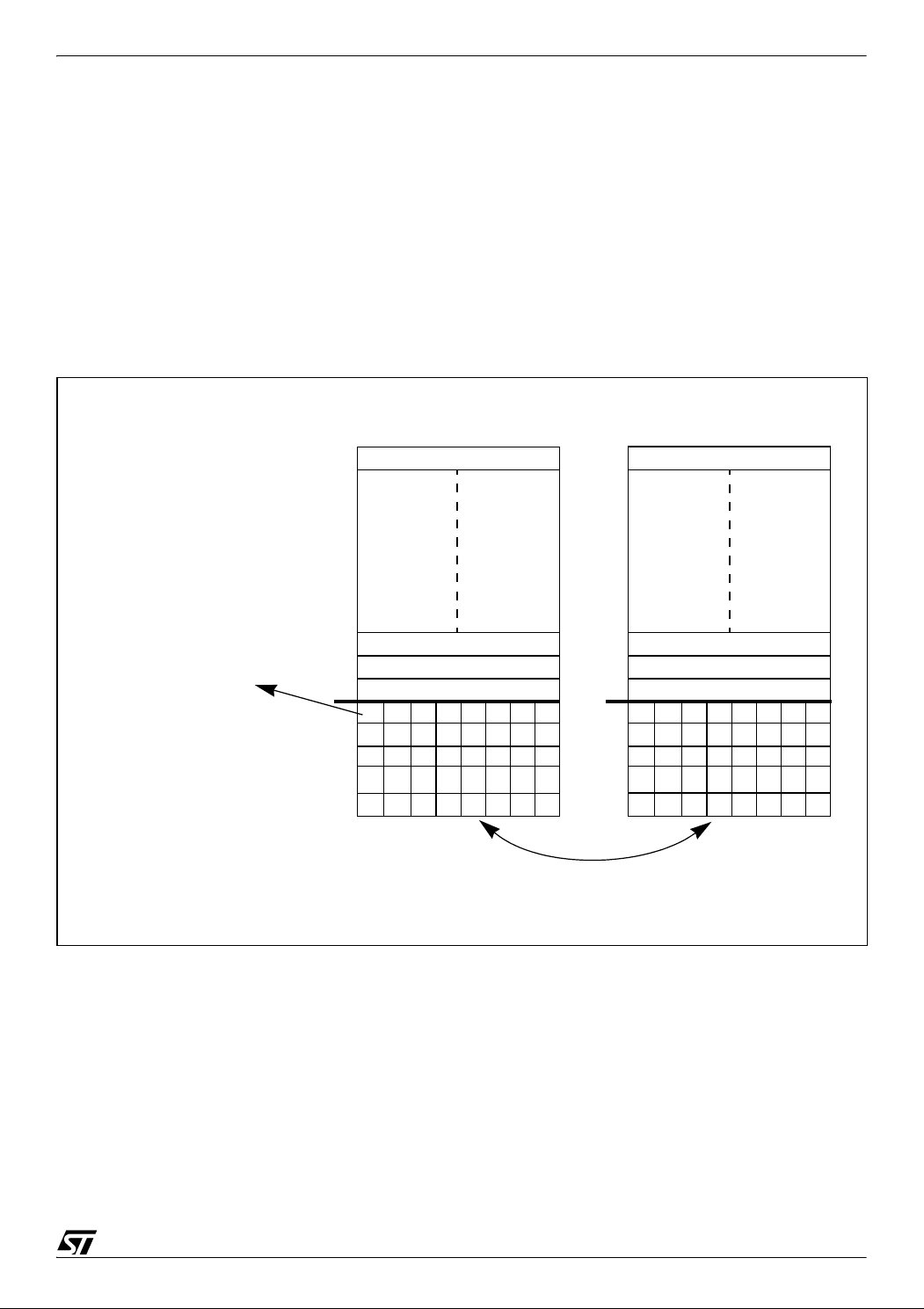
Figure 2. Software example concept
STR71x Flash Sector 0 STR71x Flash Sector1
EEPROM Emulation with STR71x
Area for Data-set storage
Area for Status bits
The last “0” corresponds
to the valid Data-set
Status bits for
valid Flash sector
0x600D: Valid sector
0xFFFF: Invalid sector
1
1
0xFFFFFFFF
0xFFFFFFFF
0xFFFFFFFF
0xFFFFFFFF
111
Data-set-1
Data-set-2
Data-set-3
0xFFFFFFFF
0xFFFFFFFF
111
1
00
0
0x600D 0xFFFF
Switch between each sector
(Erase one when full)
11
1
1
In this example a sector is erased only when it is full and the last word on each sector indicates
the status of the corresponding sector:
– 0x600D (Good) indicates a valid sector,
– 0xFFFF (Default value after an erase operation) indicates an invalid sector.
This software implements also a status bit for each Data-set. When a new Data-set is written
to the Data-set area, the software will reset the corresponding bit in the status bits area.
Figure 2. shows an example of a mechanism for setting the status bits in the status bit area.
This figure shows that Data-Set-3 is the valid one because there is three ‘0’s in the status bit
area.
Note: This mechanism takes into account the case when the Data-Set value is 0xFFFFFFFF which is the
default value after an erase operation.
4.2 SOFTWARE OUTPUT FUNCTIONS
There are three output functions in the software as described below.
13/19
Page 14

EEPROM Emulation with STR71x
4.2.1 EEPROM_Init
This function must be called only once at the beginning of the user code or when a full erase
is required.
This function initializes the Flash, erases the two correspondent sectors and marks the first as
valid by writing 0x600D in the last word of this sector.
The EEPROM_Init function is called as follows:
/* Initialize the EEPROM */
EEPROM_Init();
4.2.2 EEPROM_DataRead
This function allows the user to read the valid Data (the last Data-Set). This function returns
the following status messages:
– EEPROM_FULL_ERASE_REQUIRED: To indicate if a full erase is required,
– EEPROM_NO_VALID_DATA: To indicate if there is no valid data to be read,
– EEPROM_SUCCESSFUL_DATA_READ: To indicate if the data is read successfully.
It uses two internal functions:
– EEPROM_GetValidSector: This function returns the valid sector,
– EEPROM_ValidDataSet: This function returns the offset of the valid Data-set (if it exists).
For this function, use the following as an example:
/* Declaration */
u32 Read_Status; /* The status of the read operation */
u32 Data_Read; /* The valid Data-set */
/* Read the valid data from valid sector */
Read_Status = EEPROM_DataRead(&Data_Read);
4.2.3 EEPROM_DataWrite
This function allows the user to write a new Data-set to the valid sector without overwriting the
old Data-set and then updates the corresponding status bit.
When the valid sector is full, the function performs the following operations:
1) copies the last Data-set to the second sector,
2) writes the new Data-set,
3) updates the Status bits,
4) marks the second sector as valid,
5) and finally erases the first sector.
14/19
Page 15

EEPROM Emulation with STR71x
With this order of execution we ensure that, even if a reset event or a power cut event occurs,
the last valid Data-Set cannot be lost.
This function returns the following status messages:
– EEPROM_FULL_ERASE_REQUIRED: To indicate if a full erase is required,
– EEPROM_SUCCESSFUL_DATA_WRITE: To indicate if the new Data-set is written suc-
cessfully.
The function EEPROM_DataWrite uses three internal functions:
– EEPROM_GetValidSector: This function returns the valid sector,
– EEPROM_ValidDataSet: This function returns the offset of the valid Data-set (if it exists),
– EEPROM_UpdateDataSet: This function is used to update the corresponding status bit.
As an example of how to use this function:
/* Declaration */
u32 Write_Status; /* The status of the write operation */
u32 Data_Set; /* The new Data-set */
/* Initialize the new Data-set */
Data_Set = 0x12345678
/* Write the new Data-set to the valid sector */
Write_Status = EEPROM_DataWrite(&Data_Set);
4.3 EEPROM OUTPUT FUNCTIONS USE EXAMPLE
In this subsection an example of how to use the three output functions of the EEPROM Emulation is presented.
The following example allows to write and read three Data-set.
15/19
Page 16

EEPROM Emulation with STR71x
Figure 3. Example of output functions use
.
.
.
#include “E3PROM.h”
volatile unsigned long Data_Read;
volatile unsigned long Write_Status;
volatile unsigned long Read_Status;
void main(void)
{
/* Initialize the EEPROM */
EEPROM_Init();
/* Write the first Data-set then read it */
Write_Status = EEPROM_DataWrite(0x11111111);
if (Write_Status == EEPROM_SUCCESSFUL_DATA_WRITE)
{
Read_Status = EEPROM_DataRead(&Data_Read);
if (Read_Status == EEPROM_SUCCESSFUL_DATA_READ)
printf(“The valid Data-set is %x\n”, Data_Read);
}
/* Write the second Data-set then read it */
Write_Status = EEPROM_DataWrite(0x22222222);
if (Write_Status == EEPROM_SUCCESSFUL_DATA_WRITE)
{
Read_Status = EEPROM_DataRead(&Data_Read);
if (Read_Status == EEPROM_SUCCESSFUL_DATA_READ)
printf(“The valid Data-set is %x\n”, Data_Read);
}
/* Write the third Data-set then read it */
Write_Status = EEPROM_DataWrite(0x33333333);
if (Write_Status == EEPROM_SUCCESSFUL_DATA_WRITE)
{
Read_Status = EEPROM_DataRead(&Data_Read);
if (Read_Status == EEPROM_SUCCESSFUL_DATA_READ)
printf(“The valid Data-set is %x\n”, Data_Read);
}
}
16/19
Page 17

EEPROM Emulation with STR71x
5 SUMMARY
This application note has shown that by careful identification of events that can happen in the
field, and by definition of the Flash organization and its associated control bits, it is possible to
define a method to substitute external EEPROM with the embedded-Flash of a microcon
troller.
Embedded aspects, handling of the different events that can happen in the field and the
needed safety level are the key factors that should influence the emulation concept described
in this application note.
-
17/19
Page 18

EEPROM Emulation with STR71x
6 REVISION HISTORY
Date Revision Description of changes
13-Jan-2005 1.0 First Release
22-Jul-2005 2.0 Added the Software example section
18/19
Page 19

EEPROM Emulation with STR71x
“THE PRESENT NOTE WHICH IS FOR GUIDANCE ONLY AIMS AT PROVIDING CUSTOMERS WITH INFORMATION
REGARDING THEIR PRODUCTS IN ORDER FOR THEM TO SAVE TIME. AS A RESULT, STMICROELECTRONICS
SHALL NOT BE HELD LIABLE FOR ANY DIRECT, INDIRECT OR CONSEQUENTIAL DAMAGES WITH RESPECT TO
ANY CLAIMS ARISING FROM THE CONTENT OF SUCH A NOTE AND/OR THE USE MADE BY CUSTOMERS OF
THE INFORMATION CONTAINED HEREIN IN CONNECTION WITH THEIR PRODUCTS.”
Information furnished is believed to be accurate and reliable. However, STMicroelectronics assumes no responsibility for the consequences
of use of such information nor for any infringement of patents or other rights of third parties which may result from its use. No license is granted
by implication or otherwise under any patent or patent rights of STMicroelectronics. Specifications mentioned in this publication are subject
to change without notice. This publication supersedes and replaces all information previously supplied. STMicroelectronics products are not
authorized for use as critical components in life support devices or systems without express written approval of STMicroelectronics.
The ST logo is a registered trademark of STMicroelectronics.
All other names are the property of their respective owners
© 2005 STMicroelectronics - All rights reserved
STMicroelectronics group of companies
Australia – Belgium - Brazil - Canada - China – Czech Republic - Finland - France - Germany - Hong Kong - India - Israel - Italy - Japan -
Malaysia - Malta - Morocco - Singapore - Spain - Sweden - Switzerland - United Kingdom - United States of America
www.st.com
19/19
 Loading...