

Page 1

APPLICATION NOTE
BPF
BPF
BPF
BPF
X
Twin LNB
X
X
X
Extension of the SRC DiSEcQ 1 standard for control of
Satellite Channel Router based one-cable LNBs
1 System overview
1.1 Description
ST Micr o el ec t ro nics has introduc ed a ne w de v ice that ta r g ets the LNB, mu lt i- s wit c h and S M ATV
market. T his de vic e, c al led S aTC R-1 (S at ell it e Ch ann el R o ute r), i s ab le to t rans la t e a tr an spon de r
to any lo ca t i on in the sat el lit e b andwidt h ( 9 50 - 2 15 0 MHz). M u lti ple SaTCR d evices co upled wi th
band-pass filters and RF matrix allow to combine transponders from different polarizations and
bands on a single coaxial cable.
The purp os e o f t hi s d oc ume nt i s t o de scri be t he A N20 56 pr oto co l e xt ens ion us ed t o c ontr o l a L N B
based on SCR technology.
1.2 St andard LNB versus S aTCR LNB
A Ku-band satellite can provide up to 4.1 GHz of useful bandwidth (2 polarizations x (12750 MHz
-10700 MHz)). A standard DVB-S tuner can receive frequencies from 950 MHz to 2150 MHz
which means slightly more than 1 GHz bandwidth.
AN2056
13/18 volts detecto r
&
22KH z detec tor
F
LO
To be ab le to r e c eiv e all the available c hannels i n t h e Ku-ban d u si ng a co nventional LNB , a s ettop box has to select the polarization and the local oscillator corresponding to the desired
LO
4 x 2
Matrix
13/18 volts detecto r
&
22KH z detec tor
F
transponder. The polarization is selected by changing the voltage of the LNB supply (13 volts for
vertica l po lar iz atio n, 18 vo lt s for hori zon tal pol ari za tion ) . The lo cal os cil l ator is select ed by addi ng
or not a 2 2 KHz ton e on t he LN B su pply (whe n 22 KHz in on th e hi ghe st LO is se lect ed) . Loc al
oscillator frequency can be 9750 MHz or 10600 MHz depending on the location of the
transponder. If the respective transpo nder is in the lower part of the spectrum (<11700MHz) the
9750 MHz LO is selected, otherwise 10600 MHz LO is selected. The tuner has to be set to the
correct frequency using the following formula:
F
tuner
= F
transponder
- F
LO
1/1205 October 2004
Page 2
AN2056
BPF
BPF
BPF
BPF
X
BPF
BPF
With a LNB integrating SaTCR-1 devices, the transponder selection (polarization, LO selection
and frequency translation) is done through a single DiSEqC command named
ODU_ChannelChange (see Section 3.2.1 on page 8)
I²C
1210 MHz
1420 MHz
LO
LO
4 x 2
Matrix
SaTCR
SaTCR
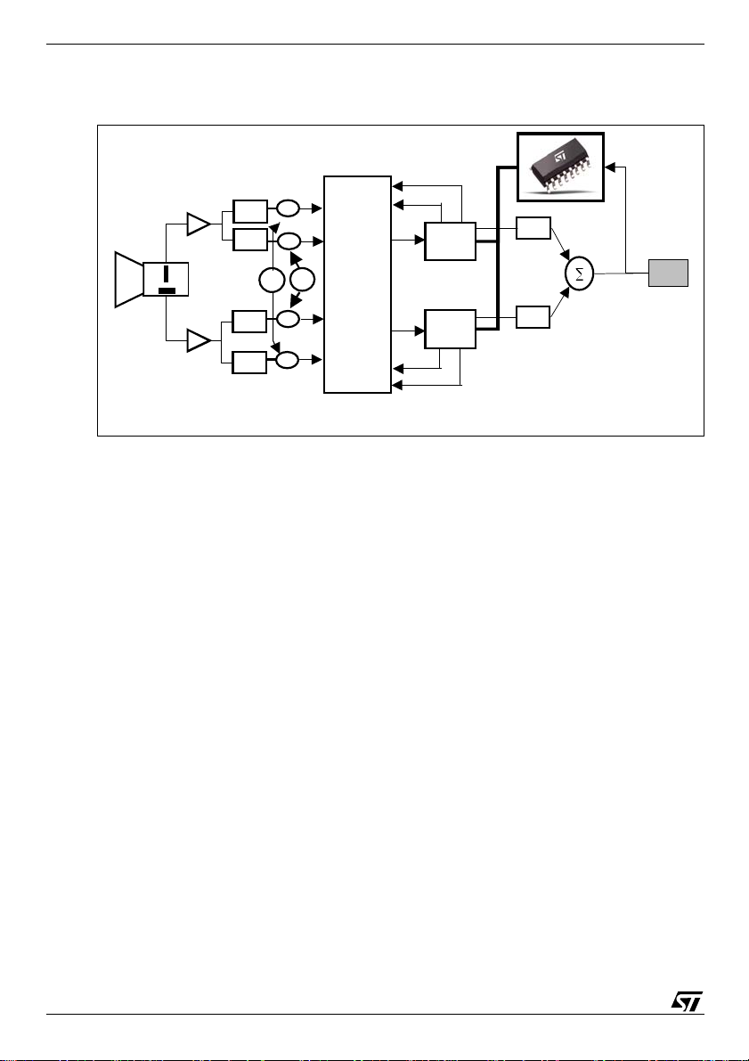
SaTCR twin LNB
First st age of a Sa TCR LNB (u p to the ma trix) is simi lar to a conven tiona l LNB. As a consequ ence ,
the tran sponder fre quency at the input of a SaTCR device is the same as Ftuner with a classical
LNB:
F
satcr_input
= F
transponder
- F
LO
Then, the SaTC R device sh ou ld t ran slate the tr an s po nder ins ide the bandw id t h o f it s ass o ci ated
band pass filter. To perform that operation, the SaTCR VCO has to be set according to the
following formula:
F
satcr_vco
= F
satcr_input
+ F
bpf
= F
transponder
- FLO + F
In addition, SaTCR LNB includes new features that allow auto-detection of its parameters.
1.3 What does this mean for the set-top box?
DiSEqC
F
bpf
1.3.1 Setup
1.3.1.1 Manual
1.3.1.2 Automatic
2/12
The control of a SaTCR LNB requires more parameters than a standard LNB. Those parameters
can be en tered manual ly by t he us er or a utomat ical ly de tected by th e set- top box . Auto mati c setup
is recommended for all set-top boxes including tone detection capabilities (see Section 2.1 on
page 5).
In this mo de , the s et -t op b ox shou ld di sp lay an LN B se t up scr e en w here t he use r shou ld en te r t he
follo wing parameters:
–• LNB type: the type of LNB used (see Table3 on page 11 for SaTCR LNB application type)
–• Local Osc il l at or f req ue nci e s: dep en ding on th e L NB typ e, 1 or 2 f req ue nci e s shou ld be ente r ed
–• SaTCR band-pass filt ers frequencies: depending on the SaTCR appl ication type, up to 8
frequencies should be entered.
In that mode, the set-top box LNB setup screen should contain a button that launches the LNB
auto-detection procedure (see Subsection 2.2: Detecting LNB parameters on page 5) using
ODU_SCRxSignalON, ODU_Config and ODU_LOFREQ DiSEqC commands.
Page 3
1.3.2 Tuning to a known transponder
950 MHz
Tuning t o a kn own tra ns pon de r is do ne by se ndi ng ODU_ChannelChange DiSEqC com man d ( t o
select the polarization, the local oscillator and to perform frequency shifting) and tuning to the
shifted freq u ency .
This procedure is described more in detail in Subsection 2.3:Searching for a channel on page 7.
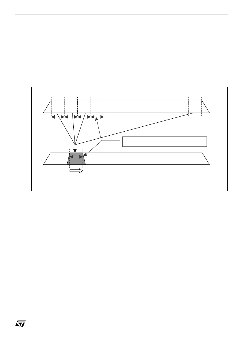
1.3.3 Scanning a complete satellite
Bandpass filter located in the LNB has limited bandwidth and this bandwidth can change from one
application to another. In consequence, the most secure solution to scan the complete satellite is
to split the bandwidth into small sections (typically 10 MHz), to shift them using
ODU_ChannelChange DiSEqC command, and to scan them using the tuner as described below:
Frequency shifting
Search range (10 MHz)
Tuner scanning
Satellite scanning
AN2056
2150 MHz
1.3.4 Standby mode
When the set-top box enters in standby mode or (in case of PVR boxes) when a tuner is not in
use, its associated SaTCR should be set in power-saving mode using ODU_Power_OFF DiSEqC
command.
1.4 How to manage multiple set-top boxes?
When usin g s eve ral set -to p bo xes co nnec ted to the sa me c abl e, the fo llowi ng ite ms shou ld b e
taken into account.
1.4.1 SaTCR allocation
In order to avoid having two set-top boxes or two tuners of the same set-top box trying to use the
same SaTCR, each set-top box tuner should be allocated a dedicated SaTCR. In consequence,
the LNB setup screen will display all SaTCR band-pass filters frequencies and the user will select
one, tw o or mor e of the m depe ndin g if th e set-t op bo x is a st andar d one (singl e tu ner), a PVR (d ual
tuner) or mu lti -tu ne r bo x. W he n in s tal li ng oth er s et -top bo xes , the us er wi ll have to ta ke ca re n ot
using an already a llocated SaTCR device.
3/12
Page 4

AN2056
1 2 3 4
13 volts
13 volts
18 volts
1210 Mhz
1420 Mhz
1680 Mhz
2040 Mhz
PVR
SaTCR bandpass filter frequency allocation
1.4.2 DiSEqC & power splitters
DiSEq C comma nds shou ld alway s be sent above a 1 8 volts D C (see Subsection 3.1: SaTCR
DiSEqC frames on page 8) in ord er to ensu re p r op er connec t io n t o t h e LNB whe n s et-top bo xe s
are conn ec t e d us in g power split ters.
Power
splitter
PVR
Sending DiSEqC t hrough power splitters
2 Description of the software architecture
This chapter describes in detail the software routines that should be implemented i nside th e STB
to support SaTCR LNB .
The basic commands need a standard DiSEqC 1 HW only. This ensures compatibility with most
of today deployed boxes. Set-up is done in a manual mode as in today’s boxes. An innovative
approach u si ng an RF tone a s b ack ch an nel c om mun ic at i on allo w s a bid ir e ctio na l c om mun ic at ion
between the STB and the SaTCR LNB whilst keeping compatibility with DiSEqC 1. Set-top boxes
featuring DiSEqC 2 can profit from the bidirectional communication of the DiSEqC 2 protocol as
4/12
Page 5

an alt ernati ve. The STB se nds r eques ts usin g the D iSEqC p rotoc ol (see Chapter3 on page 8)
1420 MHz
and the SaTCR LNB answers using RF tones. SaTCR answers are binary. If the tone is located
exactly at the center of the band-pass filter, the answer is TRUE. If the tone is located 24 MHz
higher than the band-pass filter frequency, the answer is FALSE.
2.1 Performing tone frequency dete ction
The purpose of this routine is to use the signal strength indicator available on any STB to perform
auto detection of the tones generated by the SaTCR LNB.
This ro ut ine assu mes that th e sc anne d ba ndw idth con tai ns o nly tone s and n o Q PSK or analo g
carriers. This condition is naturally guaranteed by the operation of the SaTCR LNB.
In a first time, the bandwidth is scanned with the tuner. For each tuner step the signal strength
(linke d to the AGC con trol le vel) sho uld be re ad fro m the dem odulato r devi ce and st ored in an
array. When the complete bandwidth has been scanned, the maximum signal strength value is
calculated. Th is value allows to calculate the threshold value used to find rising and falling edges
of the ton e . Th e tone freq ue nc y is lo cated in th e m id dle of th e se gm ent deli m ite d by r is in g (start)
and falling (stop) edges.
AN2056
Cable spectrum
Signal strenght
indicator value
Signal > threshold
In order to have an accurate estimation of the tone frequency, the scan step should be as small
as possible (1 MHz gives a good accuracy). Rising and falling edge frequencies depend on the
tuner low-pass filter bandwidth, the smaller this filter bandwidth is the closer will be the edges from
the to ne f r equency. The tu ne r f ilter ba nd w id th s h o ul d b e greater than tu ne r s te p divide d by t w o,
to avoid un sca nn ed zo ne s. To b e a bl e to ma ke the di ffe r enc e b etw een two co ns ec utiv e t o ne s, t he
tuner low-pass filter bandwidth should be less than the minimum dist ance between the two tones
divided by two. In case of SaTCR applications, for implementing a proper process of the tone
detec tion, tu ner l ow-p ass filt er b andw idt h sh ould be l es s tha n 50 MHz . By c onv entio n, the tone
frequency is generated at frequency integer multiple of 2 MHz.
In summary:
–• Tuner step as small as possible
–• (Tuner step / 2) < low-pass filter bandwidth < 50 MHz
2.2 Detecting LNB parameters
To be able to setup a bidirectional communication it is mandatory to know at least one band-pass
filter ce nter fr eq ue nc y. In con se quen ce, t he ba nd - pas s fil t er ce nt er f re que nc y de tec ti on sh ould be
done before appl ication type and LO frequen c ies detection.
Tuner lowpass filter bandwidth X 2
stop start
Tone frequency = start + (stop-start)/2
Tone frequency detection
Max
Threshold
5/12
Page 6

AN2056
the bandpass
2.2.1 Band-pass filters center frequencies
The purpose of this routine is to detect all band-pass filters center frequencies.
ODU_SCRxSignal_ON
Send
command to put all SatCR into tone mode
DiSEqC
2.2.2 Application type
The purpose of this routine is to rec ognize the type of SaTCR LNB connected to the STB.
Example of a spectrum provided by quad SatCR
LNB after ODU_SCRxSignal_ON command
Perform tone detection on the complete tuner
bandwidth (950MHz-2150MHz).
Store bandpass filter center frequencies
ODU_Config
Send
with application type = 1 and desired
Perform tone detection on
filter bandwidth of the selected SatCR
DiSEqC command
SaTCR number
Tone frequency = BPF frequency + 24MHz
Tone frequency = BPF frequency
Store application type
Send ODU_Config DiSEqC command
with next application type
6/12
Page 7

2.2.3 LO frequencies
mber =
Perform t one detection on the bandpas s
nd
The purpose of this routine is to detect SaTCR LN B local oscillator s frequencies.
ODU_LOFREQ
Send
command with Local oscillator nu
0 (none) and desired SaTC R number
filter bandwidth of the selected SaTCR
Tone fr equency
=
BPF freq uency + 24MHz
DiSEqC
Send
Tone frequency = BPF frequency
Store local oscillator frequency
ODU_ LOFREQ
with next local oscillator number
AN2056
DiSEqC comma
2.3 Searching for a channel
The purpose of this routine is to lock on a satellite transponder using SaTC R LNB.
End of LO table?
YES
End
ODU_ ChannelChange
Send
transponder into sel ected SatCR ban dpass filter.
=
DiSEqC comm and to translate the desired
SaTCRdesirednumberSaTCR
=
Tuningbyte
Compute of fs et between tr ansponder and bandpass filter center frequency
=
4
bpf
Search for the channel in the range
[]
NO
&
+−
FFF
bpfLOrtransponde
−
350
4)350( ×+−= TuningbyteFOffset
MHzOffsetFbpfMHzOffsetFbpf 5)(,5)( +−−−
onpolarizatibandrtranspondeondependsnumberLNB
7/12
Page 8

AN2056
2.4 Power saving
The purpose of this routine is to turn off unused SaTCR devices.
Send ODU_ PowerOFF DiSEqC command to switch off desired SatCR.
3 DiSEqC commands
This ch ap ter desc rib es t he SaT CR LN B DiSEqC com m ands. Th e co mm a nds have be en defin ed
in a way to be fully compatible with the existing DiSEqC 1 protocol.
The basic (unidirectional) LNB control is possible with only two commands
(ODU_Channel_Change, ODU_PowerOff), whereas some additional (bi-directional) commands
(ODU_SCRxSignalOn, ODU_Config, ODU_Lofreq) allow for so phisticated automatic installation
routines using the above described RF tone approach.
3.1 SaTCR DiSEqC frames
DiSEq C protocol u sed by SaTCR LNBs is the sam e as conve ntional DiSEqC 1 except that
commands have to be sent above a 18 volts DC instead of 13 volts DC (see §1.4.2????). The
delay b etw een 13 t o 1 8 v olt s s wit ch in g and t he be gin ni ng of a D iSE qC fra me sh oul d be mo r e tha n
4ms.
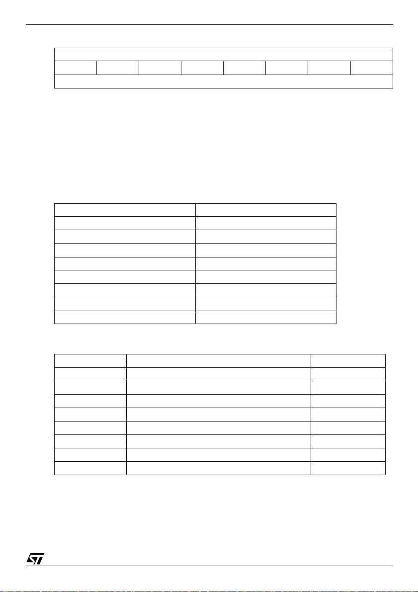
DiSEqC frame requires 5 bytes:
Framing Address Command Data1 Data2
E0 10/11 5A/5B XX XX
3.2 Mandatory DiSEqC commands
This is the min imum se t of co mmand s that sh ould be implem ente d in a set -top bo x in orde r to
control SaTCR LNB. All of them us e the DiSEqC command 5A (hex).
3.2.1 ODU_ChannelChange
E0 10 5A channel_byte1 channel_byte2
Allows to select which LNB feed is routed on a SaTCR device and to program the SaTCR
frequency.
Bit 7Bit 6Bit 5Bit 4Bit 3Bit 2Bit 2Bit 0
SaTCR number (Table 1) LNB number (Table 2) T[9:8]
8/12
channel_byte1
Page 9
AN2056
4
channel_byte2
Bit 7Bit 6Bit 5Bit 4Bit 3Bit 2Bit 2Bit 0
T[7:0]
T is the tuning byte used to program SaTCR VCO frequency. In order to limit the number of
transmitter bits to 10 a constant value (350) is substracted. The transmitted tuning byte can be
comput e d us in g the fo ll ow i ng for m ul a:
Fvco
T
------ ------- -350–=
Example:
–Fvco = 4 300 MHz T=(4300/4) - 350 =725 (dec) 2D5 (hex)
–Fvco = 3 100 MHz T=(3100/4) - 350 =425 (dec) 1A9 (hex)
–Fvco = 1 900 MHz T=(1900/4) - 350 =125 (dec) 7D (hex)
Table 1.
SaTCR number
SaTCR1 0
SaTCR2 1
SaTCR3 2
SaTCR4 3
SaTCR5 4
SaTCR6 5
SaTCR7 6
SaTCR8 7
By co nventio n, the SaTC R1 is a llocat ed th e lowes t IF f reque ncy, t he SaTC R2 i s alloca ted th e
second and so forth.
Table 2.
Satellite LNB number
Position A Low band / vertical polarization 0
High band / vertical polarization 1
Low band /horizontal polarization 2
High band / horizontal polarization 3
Position B Low band / vertical polarization 4
High band / vertical polarization 5
Low band /horizontal polarization 6
High band / horizontal polarization 7
9/12
Page 10

AN2056
3.2.2 ODU_PowerOFF
E0 10 5A poweroff_byte 00
Puts the selected SaTCR device into low-power mode
poweroff_byte
Bit 7Bit 6Bit 5Bit 4Bit 3Bit 2Bit 2Bit 0
SaTCR number (see Table 1)00000
3.3 Optio nal DiSEqC command s
This set of commands associated with the tone detection algorithm allows set-top boxes to
perfor m auto-de tection of SaTCR LN B parame ters. All of them use the DiSEqC c ommand 5B
(hex) which gives access up to 32 sub-functions. The following table describes the sub-function
mapping:
Sub-function number
ODU_SCRxSignal_ON 00h
ODU_Config 01h
ODU_LoFreq 02h
Not allocated 03h..1Fh
3.3.1 ODU_SCRxSignal_ON
E0 10 5B subfunction_byte 00
Each SaT CR generates a tone at t he center frequency of its associated band-pass filter.
subfunction_byte
Bit 7Bit 6Bit 5Bit 4Bit 3Bit 2Bit 2Bit 0
SaTCR number = 0 Sub function = 0
3.3.2 ODU_Config
10/12
Example of a spectrum provided by quad SaTCR LNB
after ODU_SCRxSignal_ON command
E0 10 5B subfunction_byte config_byte
Allows to check the applic ation nu mber. A tone is generated at the center frequency of the bandpass filter of the selected SaTCR if application number is ok o therwise the tone is 24MHz higher.
subfunction_byte
Bit 7Bit 6Bit 5Bit 4Bit 3Bit 2Bit 2Bit 0
SaTCR number (see Table 1) Sub function = 1
config_byte
Bit 7Bit 6Bit 5Bit 4Bit 3Bit 2Bit 2Bit 0
Application number (see Table 3)
Page 11

Table 3.
Application number
Not allocated 00h
Single SaTCR & Legacy 01h
Twin SaTCR (Standard band RF) 02h
Twin SaTCR & legacy (Standard band RF) 03h
Quad SaTCR (Standard band RF) 04h
Double twin SaTCR (Standard band RF) 05h
Twin SaTCR (Wide band RF) 06h
Twin SaTCR & legacy (Wide band RF) 07h
Not allocated 08h..0Fh
Reserved for operator 10h..1Fh
Reserved for operator 20h..2Fh
Not allocated 30h..FFh
Note:
1. •Legacy: conventional output signal structure, fully occupied bandwidth from 950 MHz to 2150 MHz. In application 03h and 07h,
the legacy signal is delivered on a separated F connector of the LNB. Application 01h is a proprietary system, in which the “legacy”
term corresponds to a specific signal structure.
2. •Standard band RF: The signal delivered to each SaTCR has 1.2GHz of bandwidth (11700-9750 or 12750-10600).
3. •Wide band RF: The signal delivered to each SaTCR comes in a 2.05 Ghz bandwidth.
3.3.3 ODU_LOFREQ
E0 10 5B subfunction_byte lofreq_byte
Allow s to che ck LN B loc al osc illa to r freq uenc ies. A tone is gen era ted at the ce nter fre quen cy of
the band-pass filter of the selected SCR if local oscillator is ok otherwise the tone is 24MHz higher.
subfunction_byte
Bit 7Bit 6Bit 5Bit 4Bit 3Bit 2Bit 1Bit 0
SaTCR number (Table 1) Sub function = 2
lofreq_byte
Bit 7Bit 6Bit 5Bit 4Bit 3Bit 2Bit 1Bit 0
Local oscillator number(see Table 4)(see Tabl e 5)
Table 4.
Local oscillator frequency Number (hexadecimal)
None (switcher) 00h
Unknown 01h
9750 MHz 02h
10000 MHz 03h
10600 MHz 04h
10750 MHz 05h
11000 MHz 06h
AN2056
11/12
Page 12

AN2056
I
s
o
d
b
ct
t
ot
a
Table 4.
Local oscillator frequency Number (hexadecimal)
11250 MHz 07h
11475 MHz 08h
20250 MHz 09h
5150 MHz 0Ah
1585 MHz 0Bh
13850 MHz 0Ch
Not allocated 0Dh.. 0Fh
Wide band LUT (see Table 5) 10h.. 1Fh
Not allocated 20h.. FFh
Table 5.
Local oscillator frequency Number (hexadecimal)
None (switcher) 10h
Unknown 11h
13250 MHz 12h
Not allocated 13h.. 1Fh
4 Revision history
Table 6. Revisi on his tor y
Date Revision Description of changes
05 October 2004 1 First issue
nformation furnished is believed to be accurate and reliable. However, STMicroelectronics assumes no responsibility for the consequence
f use of such information nor for any infringement of patents or other rights of third parties which may result from its use. No license is grante
y implication or otherwise under any patent or patent rights of STMicroelectronics. Specifications mentioned in this publication are subje
o change without notice. This publication supersedes and replaces all information previously supplied. STMicroelectronics products are n
uthorized for use as critical components in life support devices or systems without express written approval of STMicroelectronics.
Australia - Belgium - Brazil - Canada - China - Czech Republic - Finland - France - Germany - Hong Kong - India - Israel - Italy - Japan -
Malaysia - Malta - Morocco - Singapore - Spain - Sweden - Switzerland - United Kingdom - United States of America
The ST logo is a registered trademark of STMicroelectronics.
All other names are the property of their respective owners
© October 2004 STMicroelectronics - All rights reserved
STMicroelectronics group of companies
www.st.com
12/12
 Loading...